


 Loading...
Outdoor Wood Burning Fireplace
OWNER’S OPERATION AND INSTALLATION MANUAL
(V)JM36, (V)JM42, (V)JM50 Series, WCM-36J, WCM-42J AND WCM-50J Wood Burning Masonry Fireplaces with Insulation
SAVE THIS BOOK
This book is valuable. In addition to instructing you on how to install and maintain your appliance, it also contains information that will enable you to obtain replacement parts or accessory items when needed. Keep it with your other important papers.
This fireplace is approved for use as a wood burning fireplace or for use with a vented gas log approved to ANS Z21.60,Z21.84orRGA2-72standardsorforusewithavent- free gas log heater approved to ANS Z21.11.2 standard.
This wood burning fireplace complies with UL127- CAN/ULS-S610-M87 standard as a FACTORY BUILT APPLIANCE.
FOR CANADA: The authority having jurisdiction (such as the municipal building department, fire department, etc.) should be contacted before installation to determine the need to obtain a permit.
INSTALLER: Leave this manual with the appliance. CONSUMER: Retain this manual for future reference.
For more information, visit www.desatech.com
 WARNING: Improper installation, adjustment, alteration, service or maintenance can cause injury, property damage or loss of life. Refer to this manual for assistance or additional information. Consult a qualified installer or local distributor.
Table of Contents
Safety................................................................... |
2 |
Glass Door Installation....................................... |
29 |
Specifications....................................................... |
3 |
Operation and Maintenance Guidelines............. |
31 |
Fireplace Installation............................................ |
6 |
Technical Service............................................... |
33 |
Venting Installation............................................... |
8 |
Replacement Parts............................................. |
33 |
Optional Gas Line Installation............................ |
13 |
Parts .................................................................. |
34 |
Brick Installation................................................. |
14 |
Accessories........................................................ |
37 |
Safety
IMPORTANT: Check local codes before installing this fireplace.
Before beginning the installation of the fireplace, read these instructions through completely.
•This DESA Heating, LLC fireplace and its components are safe when installed according to this installation manual. Unless you use DESA Heating, LLC components, which have been designed and tested for the fireplace system, you may cause a fire hazard.
•The DESA Heating, LLC warranty will be voided by and DESA Heating, LLC disclaims any responsibility for the following actions.
a.Modification of the fireplace, components, doors, air inlet system and damper control.
b.Use of any component part not manufactured or approved by DESA Heating, LLC in combination with a DESA Heating, LLC fireplace system.
Proper installation is the most important step in ensuring safe and continuous operation of the fireplace. Consult the local building codes as to the particular requirements concerned with the installation of all factory built fireplaces.
 WARNING: Do not install a fireplaceinsertinthisboxunless the manufacturer's instructions with the insert specifically state thisfireplacehasbeentestedfor use with this insert.
FOR YOUR SAFETY
•Do not store or use gasoline oranyotherflammablevapors or liquids in the vicinity of this or any other appliance.
•Due to high temperatures, the appliance should be located out of traffic and away from furniture and draperies.
•Do not place clothing or other flammablematerialsonornear the appliance.
•Never leave children unattended when a fire is burning in the fireplace.
 WARNING: Use solid wood or processed solid fuel firelogs only. When processed wood fuel firelogsareused,donotpokeor stir the logs while they are burning. Use only fire logs that have beenevaluatedfortheapplication in fireplace and refer to fire log warnings and caution markings on packaging prior to use.
Thisfireplaceisnotintendedtobe used as a substitute for a furnace to heat an entire home. Use for supplemental heat only.
www.desatech.com |
122273-01A |
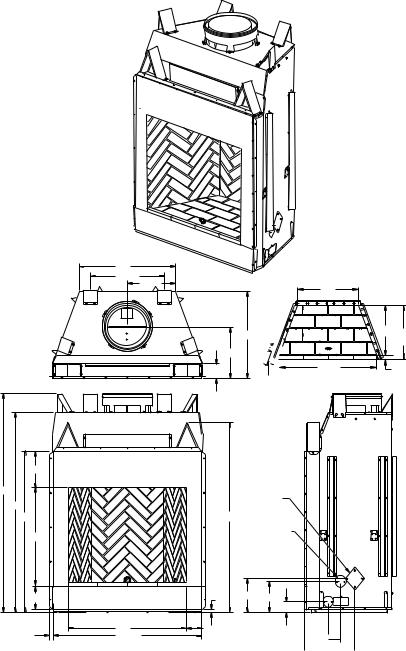
Specifications
36" mODELS
29" |
|
22 |
1/2" |
|
14 1/2" |
|
22" |
26 5/8" |
18 3/8" 19 13/16" |
|
(Ref.) |
15 5/8" |
|
|
4 1/2" |
35 3/8" |
1 5/16" |
|
36" HEARTH |
|
11" |
|
67" |
|
61" |
|
49" |
58" |
30" |
|
7" |
1" |
1" |
36" |
4 1/2" |
45 1/8" |
|
OUTSIDE AIR |
ACCESS |
GAS LINE |
ACCESS |
10 1/2" 9 1/2" |
3 1/2" |
 7 1/4"
 11"
11" 
 15 1/4"
Figure 1 - 36" Models (V)JM36 Series and WCM-36J
122273-01A |
www.desatech.com |
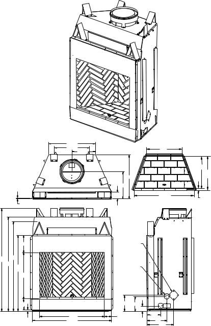
Specifications Continued
42" Models
30 1/2" |
|
|
|
|
22 3/4" |
25" |
|
|
|
15 3/4" |
|
|
|
|
|
|
22 1/2" |
||
|
|
|
23 13/16" |
|
29" |
|
|
(Ref.) |
|
17 5/8" |
|
|
|
|
4 3/8" |
41 3/8" |
1 |
5 |
/16" |
|
|
|
||
5/8" |
42" HEARTH |
|
|
|
|
|
OUTSIDE |
|
11" |
AIR |
|
ACCESS |
|
67" |
58" |
|
61" |
GAS LINE |
|
|
49" |
|
|
30" |
ACCESS |
|
|
|
7" |
|
|
42" |
1" |
51 1/8" |
10 1/2" 9 1/2" |
|
3 1/2" |
|
4 1/2" |
81/2" |
|
13" |
|
17" |
Figure 2 - 42" Models (V)JM42 Series and WCM-42J
www.desatech.com |
122273-01A |

Specifications Continued
50" Models
38 1/2" |
|
|
|
24" |
33" |
|
|
19 1/4" |
|
|
|
|
|
23 13/16" |
|
|
22 |
1/2" |
|
|
|
(Ref.) |
|
28 1/2" |
|
|
|
17 5/8" |
|
|
|
43/8" |
49 3/8" |
1 5/16" |
|
50" HEARTH |
|||
|
|
|
|
|
OUTSIDE |
|
11" |
|
AIR |
|
|
ACCESS |
|
|
|
|
|
67" |
58" |
|
GAS LINE |
|
|
||
61" |
49" |
|
ACCESS |
|
30" |
|
|
|
7" |
|
10 1/2"9 1/2" |
|
|
|
3 1/2" |
|
1" |
4 1/2" |
|
|
50" |
8 1/2" |
|
|
59" |
|
13" |
|
|
|
17" |
Figure 3 - 50" Models (V)JM50 Series and WCM-50J
122273-01A |
www.desatech.com |
|
Fireplace Installation
selecting location
To determine the safest and most efficient location for the fireplace, you must take into consideration the following guidelines:
1.The location must allow for proper clearances (see Figures 4 and 5).
2.Consider a location where fireplace will not be affected by drafts, air conditioning ducts, windows or doors.
3.A location that avoids cutting of joists or roof rafters will make installation easier.
4.An outside air kit is available with this fireplace (see Optional Outside Air Kit on page 8).
Minimum clearance to combustibles
Back and sides of fireplace |
1 1/2" min.* |
|
Front of fireplace |
|
48" min. |
Floor** |
|
0" min. |
Perpendicular wall to opening |
18" min. |
|
36" Models |
|
12" min. |
Top spacers |
|
0" min. |
Mantel clearances |
see Mantels, page 7 |
|
Chimney outer pipe surface |
2" min. |
|
36" Model |
|
1" min. |
* Not required at nailing flanges ** See step 2 of Framing
Framing
1.Frame opening for fireplace using dimensions shown in Figures 4 and 5.
2.If fireplace is to be installed directly on carpeting, tile (other than ceramic) or any combustible material other than wood flooring, fireplace must be installed upon a metal or wood panel extending full width and depth of fireplace.
3.Set fireplace directly in front of this opening and slide unit back until nailing flanges touch side framing.
4.Check level of the fireplace and shim with sheet metal if necessary.
5.Before securing fireplace to prepared framing, ember protector (provided) must be placed between hearth extension (not supplied) and under bottom front edge of fireplacetoprotectagainstglowingembers falling through. If fireplace is to be installed on a raised platform, a Z-type ember protector (not supplied) must be fabricated to fit your required platform height. Ember protector should extend under fireplace a
minimum of 1 1/2". Ember protector should be made of galvanized sheet metal (28 gauge minimum to prevent corrosion.
6.Using screws or nails, secure fireplace to framing through flanges located on sides of fireplace.
 WARNING: Do not pack required air spaces with insulation or other materials.
Minimum/Maximum Chimney Height for
Residential Installation
Minimum height of chimney, measured from base of fireplace to flue gas outlet of termination, is 16 feet for straight flue or a flue with one elbow set. Maximum distance between elbows is 6 feet. For systems with two elbow sets, minimum height is 22 feet. Maximum height of any system is 50 feet.This measurement includes fireplace, chimney sections and height of termination assembly at level of the flue gas outlet (see Figure 15, page 11).
Minimum/Maximum Chimney Height for
Outdoor Installation
Minimum height of chimney, measured from base of fireplace to flue gas outlet of termination, is 9.5 feet (minimum of 4 feet of chimney pipe sections required for outdoor installation).
 45.25" (36" Models)
51.25" (42" Models)
59" (50" Models)
67.125"
58.125"
 30.125"
  28.250" (36" Models)
Figure 4 - Framing Dimensions
|
Maintain 1 1/2" |
|
61" (36" Models) |
Clearance |
|
at Sides and |
||
65" (42" Models) |
||
Back of Fireplace |
||
71" (50" Models) |
||
|
||
|
1 1/2" Clearance |
|
|
Not Required at |
|
|
Nailing Flanges |
86.5" (36" Models)
92" (42" Models)
100" (50" Models)
Figure 5 - Corner Installation
www.desatech.com |
122273-01A |
Fireplace Installation
Continued
Note: For outdoor installations, fireplace enclosure must allow for adequate drainage and fresh air ventilation. It is recommended that a sealed, corrosion resistant catch pan with provision for drainage be installed under fireplace within fireplace enclosure.
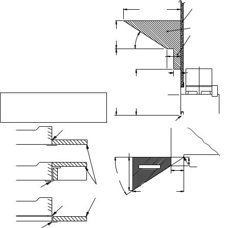
Hearth Extension
A hearth extension projecting a minimum of 20" in front of and a minimum of 12" beyond each side of fireplace opening is required to protect combustible floor construction in front of fireplace. Fabricate a hearth extension using a material which meets the following specifications: a layer of noncombustible, inorganic material having a thermal conductivity of K=0.84 BTU IN/FT, HR. F (or less) at 1" thick. For example, if the material selected has a K factor of 0.25, such as glass fiber, the following formula would apply:
0.25 x 1.0" = 0.30" thickness required
0.84
Thermal conductivity "K" of materials can be obtained from manufacturer or supplier of noncombustible material. If hearth extension is to be covered, use noncombustible material such as tile, slate, brick, concrete, metal, glass, marble, stone, etc. Provide a means to prevent hearth extension from shifting and seal gap between fireplace frame and hearth extension with a noncombustible material (see Figure 6).
 WARNING:Hearthextension
is to be installed only as shown
in Figure 6.
Seal Gap
Fireplace Front
Ember Protector
Fireplace Front |
|
Raised Hearth |
|
Ember Protector |
Hearth |
|
|
|
Extension |
Fireplace Front |
Seal Gap |
Elevated |
|
Ember Protector |
|
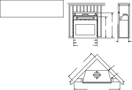
Mantels
Amantelmaybeinstalledifdesired(seeFigure 7). Woodwork such as wood trims, mantels or any other combustible material projecting from front face must not be placed within 12" (36" Models) or 18" (42/50" Models) of fireplace opening.Combustiblematerialsabove12"(36" Models) or 18" (42/50" Models) and projecting more than 1 1/2" from fireplace must not be placedlessthan15"(36"Models)or21"(42/50" Models) from the top opening of the fireplace (NFPA STD 211, Sec. 7-3.3.3).
Mantels or any other combustible material also may come up to side edge of black metal face of fireplace as long as projections from front face fall within limit shown in Figure 7.
|
|
12 1/4" Ref. |
Combustible |
|
|
|
Material |
||
|
|
|
Safe |
|
|
|
|
Zone for |
|
6" |
|
Projection of |
||
|
Combustible |
|||
Ref. |
33° |
|||
Materials |
||||
|
|
|||
Min.15"(36" Models) |
|
3" Nom. |
|
|
Min.21" (42/50" Models) Min.12" Models)(36" Min.18" (42/50" Models) |
|
|||
|
|
11/2" Max. |
|
|
|
|
|
Upper |
|
|
|
|
Section of |
|
|
|
|
Fireplace |
|
|
|
Fireplace Opening |
|
|
Top View of Fireplace
7.75" (36" Models) |
FIREBOX |
|
11.5" (42/50" Models) |
|
|
|
3" Max. |
|
SAFE ZONE |
4.5" |
Combustible |
33° |
Material |
|
|
Must Not |
|
Min. to |
|
|
|
Overlap |
|
Perpendicular |
|
Front Face |
Side Wall |
|
|
12" - 36" Models |
|
|
18" - 42/50" Models |
|
|
Figure 7 - Mantel Clearances to |
||
Combustible Material |
|
|
Figure 6 - Hearth Extension
122273-01A |
www.desatech.com |
Venting Installation
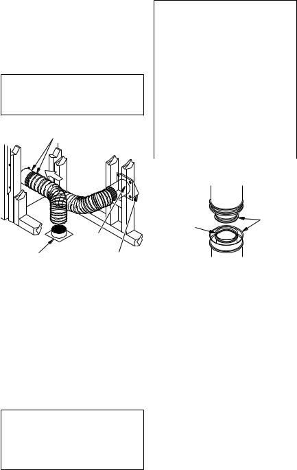
Optional Outside air Kit (Model ak4/ak4f)
The installation of an outside air kit should be performed during the rough framing of the fireplace due to the nature of it's location. Outside combustion air is accessed through a vented crawl space (AK4F) or through a sidewall (AK4).
 CAUTION: Combustion air inlet ducts shall not terminate in attic space.
Secure to Collars with Metal Tape, Screws or Straps (Min. of 1/4" x 20" in size)
Air Inlet |
||
Location |
||
Must Allow |
||
For Bushes |
||
or Snow |
||
|
Air Inlet |
|
|
Eyebrow |
|
Vented Crawl Space |
Vent Hood |
|
Required for |
||
(Check Local Codes |
||
Wall Installation |
||
Before Installing in a |
||
|
||
Vented Crawl Space) |
|
|
Figure 8 - Outside Air Kit
Chimney Pipe
The DESA Heating, LLC chimney system consists of 12", 18", 24", 36" and 48" snaplock, double-wall pipe segments, planned for maximum adaptability to individual site requirements. Actual lengths gained after fitting overlaps must be taken into consideration (lineal gain) and are given in the lineal gain chart (see Figure 9). Lineal Gain is the actual measurable length of a part after two or more parts are connected. For Canada, use chimney parts designated "HT".
 WARNING: The opening in the collar around the chimney at the top of the fireplace must not be obstructed.Neveruseblowninsulation to fill the chimney enclosure.
LINEAL GAIN
PART NO. |
DESCRIPTION |
GAIN |
|
Georgian |
Fireplace |
66 1/2" |
|
12-12DM |
Pipe Section |
10 5/8" |
|
12-12HT |
|||
|
|
||
18-12DM |
Pipe Section |
16 5/8" |
|
18-12HT |
|||
|
|
||
24-12DM |
Pipe Section |
23 5/8" |
|
24-12HT |
|||
|
|
||
36-12DM |
Pipe Section |
34 5/8" |
|
36-12HT |
|||
|
|
||
48-12DM |
Pipe Section |
46 5/8" |
|
48-12HT |
|||
|
|
||
RLT-12D |
Round Termination |
7 3/4"* |
|
RLT-12HT |
|
|
|
STL-12D |
Square Chase-Top |
7" to 15"* |
|
with Slip Section |
* The lineal gain for the terminations is measured to the flue gas outlet height.
12" Galvanized Outer Pipe 
12 3/8" |
Hemmed |
Stainless |
End |
|
|
Inner Pipe |
|
Figure 9 - Lineal Gain
Assembly and installation of double wall chimney system
Each double wall chimney section consists of a galvanized outer pipe, a stainless steel inner flue pipe and a wire spacer. The pipe sections must be assembled independently as the chimney is installed. When connecting chimney directly to the fireplace, the inner flue pipe section must be installed first with the lanced side up. The outer pipe section can then be installed over 5 the flue pipe section with the hemmed end up. Press down on each pipe section until the lances securely engage the hem on the fireplace starter. The wire will assure the proper spacing between the inner and outer pipe sections.
Continue to assemble chimney sections as outlined above, making sure that both the inner and outer pipe sections are locked together. When installing double wall snap-lock chimney together, it is important to assure the joint between the chimney sections is locked. Check by pulling chimney upward after locking. The chimney will not come apart
www.desatech.com |
122273-01A |
Venting Installation
Continued
if properly locked. It is not necessary to add screws to keep the chimney together (exception, see Figure 10).
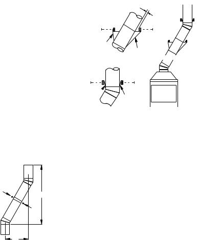
Using ELBOW offsets (30E-12DM)
1.To achieve desired offset, you may install combinations of 12", 18", 24", 36" and 48" length of double wall pipe (see offset chart and Figure 10).
2.Chimney weight above offset rests on return elbow. Straps must be securely nailed to rafters or joists (see Figure 11, details A and B).
3.Maximum length of pipe between supports (return elbow or 12S-12DM) is 6' of angle run. Maximum of two 6' angle run sections per chimney system (see Figure 12, page 10).
OFFSET |
RISE |
|
CHIMNEY LENGTH |
|
||||
A |
B |
12" |
18" |
24" |
36" |
48" |
||
4 3/8" |
16 3/8" |
|
ELBOW SET ONLY |
|
||||
9 3/4" |
25 1/2" |
1 |
|
|
|
|
|
|
12 3/4" |
30 3/4" |
|
|
1 |
|
|
|
|
15" |
34 3/4" |
|
|
|
1 |
|
|
|
18" |
40" |
1 |
|
1 |
|
|
|
|
21 1/4" |
46 1/4" |
|
|
|
|
1 |
|
|
23 3/4" |
49 1/4" |
|
|
1 |
1 |
|
|
|
27 3/4" |
56 3/4" |
|
|
|
|
|
|
1 |
30" |
60 3/4" |
|
|
1 |
|
1 |
|
|
33" |
66" |
|
|
|
|
|
|
1 |
36" |
71" |
|
|
1 |
|
|
|
1 |
38 1/4" |
75" |
|
|
|
|
2 |
|
|
41 1/4" |
80 1/4" |
1 |
|
1 |
|
1 |
|
|
45" |
86 3/4" |
|
|
|
|
2 |
|
|
46 3/4" |
89 1/2" |
1 |
|
1 |
|
|
|
1 |
51" |
97" |
|
|
|
|
1 |
|
1 |
53 1/4" |
101" |
|
|
|
|
2 |
|
|
56 1/4" |
106 1/4" |
|
|
|
|
|
|
2 |
59 1/4" |
111 1/2" |
|
|
1 |
|
1 |
|
1 |
61 3/4" |
115 1/2" |
1 |
|
|
|
|
|
2 |
64 3/4" |
120 3/4" |
|
|
1 |
|
|
|
2 |
68 1/4" |
127" |
|
|
|
|
2 |
|
1 |
70" |
130" |
1 |
|
1 |
|
|
|
2 |
74 1/4" |
137 1/2" |
1 |
|
|
|
2 |
|
1 |
76 3/4" |
141 1/2" |
|
|
1 |
|
2 |
|
1 |
79 3/4" |
146 3/4" |
|
|
|
|
4 |
|
|
OFFSET CHART (22-50 FT. SYSTEM HEIGHT)
4.All pipe connections between the offset and return must be secured with two screws on the outer pipe only (see Figure 10). Do not penetrate the inner stainless.
See Detail A

 2" Min.
Straps
Detail BStraps |
See Detail B |
|
Angle Firestop |
||
|
Straps
Straps
Detail A
Return Elbow
Figure 11 - Ceiling Support Pipe
12S-12DM
Screws
B
A
Figure 10 - Elbow Offset
122273-01A |
www.desatech.com |
Venting Installation
Continued
|
|
Return |
Return |
|
|
|
Elbow |
Elbow |
|
Offset |
|
Offset |
Return |
|
Elbow |
|
Elbow |
|
|
|
Elbow |
|
||
|
6' Max. |
6' Max. Ceiling |
|
|
|
|
|
||
Return |
|
|
Support Pipe |
|
|
Return |
12S-12DM |
6' Max. |
|
Elbow |
|
|||
|
|
|||
|
|
Elbow |
|
|
6' Max. |
Offset |
|
Offset |
|
|
Elbow |
6' Max. Elbow |
6' Max. |
Offset |
|
|
Elbow |
|
|
A |
B |
C |
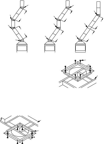
Figure 12 - Typical Offset Terminations
Firestop Spacers (FS-10, 1100EFS-10DM for 36" Models)
Firestop spacers are required at each point where the chimney penetrates a floor space. Their purpose is to establish and maintain the required clearance between the chimney and the combustible materials. When the pipe passes through a framed opening into a living space above, the firestop must be placed onto the ceiling from below as shown in Figure 13.
They also provide complete separation from one floor space to another or attic space as required by most codes. When the double wall pipe passes through a framed opening into an attic space, the firestop must be placed into an attic floor as shown in Figure 14.
Existing
Ceiling
Frame
Firestop
Spacer
 Screws or Staples
(Min. of 8)
Figure 13 - Firestop Spacer with Living Space Above Ceiling
Screws or Staples Firestop (Min. of 8)
Spacer 
Existing |
Ceiling |
Frame |
Figure 14 - Firestop Spacer with Attic Space Above Ceiling
Penetrating the roof
To maintain a 1" (36" Models) or 2" (42/50" Models) clearance to the pipe on a roof with a pitch, a rectangular opening must be cut.
1.Determine center point through which pipe will penetrate roof.
2.Determine center point of roof. Pitch is distance the roof drops over a given span, usually 12". A 6/12 pitch means that roof drops 6" for each 12" measured horizontally down from roof rafters.
3.Use roof opening chart (Figure 15, page
11)to determine correct opening length and flashing required.
4.Remove shingles around opening measured. Cut out this section.
10 |
www.desatech.com |
122273-01A |
Venting Installation
Continued
5.Add next sections of pipe until end penetrates roof line. Check to see that proper clearances are maintained. Extend chimney by adding sections of double wall pipe until pipe is minimum of 30" above highest point of roof cutout. Termination and chimney must extend a minimum of 36" above highest point where it passes through roof.
17" Min. |
30" Min. |
|
|
|
1" Min. |
|
1" Min. |
|
1" Min. |
|
Opening "A" |
Pitch |
Slope |
Opening |
Used Flashing |
|
|
|
"A" Max. |
Model No. |
|
Flat |
0° |
17" |
V6F-10DM |
|
0-6/12 |
26.6° |
19" |
V6F-10DM |
|
6/12- |
45.0° |
24" |
V12F-10DM |
|
12/12 |
||||
|
|
|
||
|
Roof Opening 36" Models |
|||
19.5" Min. |
|
30" Min. |
||
|
|
|
||
|
|
2" Min. |
|
|
|
|
|
2" Min. |
|
|
|
2" Min. |
|
|
|
|
|
Opening "A" |
|
Flashing installation (v6f-10dm or v12f-10dm)
Determine the flashing to be used with the roof opening chart. Slide flashing over pipe until base is flat against roof. Replace as many shingles as needed to cover exposed area and flashing base. Secure in position by nailing through shingles (see Figure 16). DO NOT NAIL THROUGH FLASHING CONE.
Installing Flashing on a Metal Roof
When installing the flashing on a metal roof, it is required that putty tape be used between the flashing and the roof.The flashing must be secured to the roof using #8 x 3/4" screws and then sealed with roof coating to prevent leakage through the screw holes. A roof coating must also be applied around the perimeter of the flashing to provide a proper seal.
Storm Collar |
Overlap |
|
Shingles Top |
||
Flashing |
||
and Sides Only |
||
Cone |
|
Nail Only
Outer
Perimeter
of Flashing
Underlap Shingles
at Bottom
Figure 16 - Flashing Installation
Storm Collar Installation (SC2-1)
Place storm collar over pipe and slide down until it is snug against the open edge of the flashing (see Figure 17). Apply waterproof caulk around the perimeter of the collar to provide a proper seal.
Pitch |
Slope |
Opening |
Used Flashing |
|
|
|
"A" Max. |
Model No. |
|
Flat |
0° |
19.5" |
V6F-10DM |
|
0-6/12 |
26.6° |
22' |
V6F-10DM |
|
6/12- |
45.0° |
27" |
V12F-10DM |
|
12/12 |
||||
|
|
|
Roof Opening 42" and 50" Models
Figure 15 - Roof Opening Measurements
Chimney |
Waterproof |
Pipe |
Caulk |
Storm |
Flashing |
Collar |
Figure 17 - Storm Collar
122273-01A |
www.desatech.com |
11 |
Venting Installation
Continued
Terminations/Spark Arrestor
The fireplace system must be terminated with the listed round top or chase terminations. In any case, refer to the installation instructions supplied with the termination.
CAUTION:Donotsealopen- |
|
|
ingsontherooftopflashing.Fol- |
|
|
low the installation instructions |
|
|
provided with the termination |
24" Min. |
|
being used. |
||
|
18"
Min.
Typ.
|
RTL-10D |
Stainless |
Level of |
Inner Flue |
|
Pipe |
Flue Gas |
|
Outlet |
Secure |
|
|
Termination |
|
|
to Outer |
Waterproof |
|
Pipe with 3 |
||
Caulking |
||
Screws |
||
Storm |
||
|
||
|
Collar |
|
|
Flashing |
|
Overlap |
|
|
Shingles (Top |
Underlap |
|
and Sides of |
Shingles |
|
Flashing Base) |
|
Figure 18 - Termination
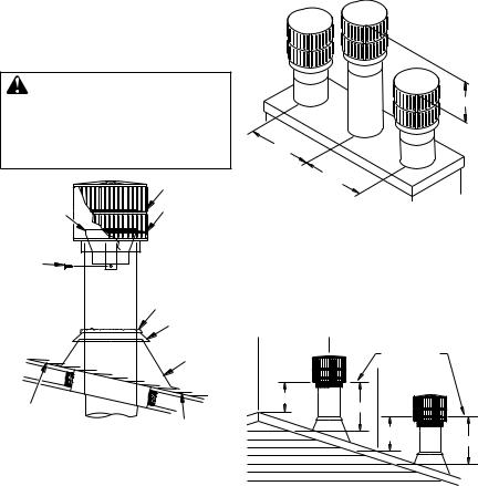
Chase installations
Instructions for chase installations are included with the chase style termination chosen. In a multiple chase installation, be sure to provide adequate distance between terminations to prevent smoke spillage from one termination to another. We suggest that terminations be separated at least 24", center to center and stacked at a vertical height difference of 18" (see Figure 19).
Note: If a decorative shroud is to be installed, contact the manufacturer for specifications.
24" Min.
Figure 19 - Multiple Chase Installation
10 foot rule
All flue gas outlet chimney terminations must extend a minimum of 3 feet in height above the highest point where it passes through the roof and must be at least 2 feet above the highest point of the roof that is within a horizontal distance of 10 feet (see Figure 20).
Level of  10'
10'  Flue Gas
Outlet  10'
10' 

2' Min.
3' Min.
2' Min. |
3' Min. |
|
Figure 20 - 10 Foot Rule
finishing the fireplace
Combustible materials, such as wallboard, gypsum board, sheet rock, drywall, plywood, etc.maymakedirectcontactwithsidesandtop around the fireplace face. It is important that combustible materials do not overlap the face itself. Brick, glass, tile or other noncombustible materials may overlap the front face provided they do not obstruct essential openings like louvered slots or any other opening. When overlapping with a noncombustible facing material, use only noncombustible mortar or adhesive.
12 |
www.desatech.com |
122273-01A |
Loading...