


 Loading...
UNVENTED (VENT-FREE) INFRARED GAS HEATER SAFETY INFORMATION AND INSTALLATION MANUAL
MODELS CTR25NR, CTR22PR, VTN25R AND VTP22R
WARNING: If the information in this manual is not followed exactly, a fire or explosion may result causing property damage, personal injury or loss of life.
—Do not store or use gasoline or other flammable vapors and liquids in the vicinity of this or any other appliance.
—WHAT TO DO IF YOU SMELL GAS
•Do not try to light any appliance.
•Do not touchany electrical switch;do notuse any phone in your building.
•Immediatelycallyourgassupplierfromaneighbor’s phone. Follow the gas supplier’s instructions.
•If you cannot reach your gas supplier, call the fire department.
—Installationandservicemustbeperformedbyaqualified installer, service agency or the gas supplier.
Save this manual for future reference. For more information, visit www.desatech.com

WARNING: Improper installation, adjustment, alteration, service or maintenance can cause injury or propertydamage.Refertothismanualforcorrectinstallation and operational procedures. For assistance or additional information consult a qualified installer, service agency or the gas supplier.
WARNING: This is an unvented gas-fired heater. It uses air (oxygen) from the room in which it is installed. Provisions for adequate combustion and ventilation air must beprovided.RefertoAirforCombustionandVentilation section on page 5 of this manual.
This appliance may be installed in an aftermarket,* permanently located, manufactured (mobile) home, where not prohibited by local codes.
This appliance is only for use with the type of gas indicated on the rating plate. This appliance is not convertible for use with other gases.
* Aftermarket: Completion of sale, not for purpose of resale, from the manufacturer
TABLE OF CONTENTS
Safety Information ............................................... |
3 |
Local Codes ........................................................ |
4 |
Product Identification........................................... |
4 |
Unpacking ........................................................... |
4 |
Product Features................................................. |
4 |
Air For Combustion and ventilation ..................... |
5 |
Installation ........................................................... |
7 |
Operating Heater............................................... |
13 |
Inspecting Heater .............................................. |
15 |
Cleaning and Maintenance................................ |
16 |
Service Hints ..................................................... |
16 |
Technical Service .............................................. |
16 |
Troubleshooting................................................. |
17 |
Illustrated Parts Breakdown .............................. |
20 |
Parts List ........................................................... |
21 |
Specifications .................................................... |
22 |
Accessories....................................................... |
22 |
Service Publications.......................................... |
22 |
Replacement Parts............................................ |
22 |
Parts Central ..................................................... |
23 |
2 |
www.desatech.com |
113261-01A |
SAFETY INFORMATION
 WARNING:Thisproductcontainsand/orgenerateschemicals known to the State of California to cause cancer or birth defects, or other reproductive harm.
IMPORTANT: Read this owner’s manualcarefullyandcompletely before trying to assemble, operate or service this heater.
Improper use of this heater can cause serious injury or death from burns, fire, explosion, electrical shock and carbon monoxide poisoning.
 DANGER:Carbonmonoxide poisoning may lead to death!
CarbonMonoxidePoisoning:Earlysignsofcarbon monoxide poisoning resemble the flu, with headaches, dizziness or nausea. If you have these signs, the heater may not be working properly. Get fresh air at once! Have heater serviced. Some people are more affected by carbon monoxide than others. These include pregnant women, people with heart or lung disease or anemia, those under the influence of alcohol and those at high altitudes.
NaturalandPropane/LPGas:NaturalandPropane/LP gases are odorless. An odor-making agent is added to these gases.The odor helps you detect a gas leak. However, the odor added to the gas can fade. Gas may be present even though no odor exists.
Make certain you read and understand all warnings. Keep this manual for reference. It is your guide to safe and proper operation of this heater.
 WARNING: Any change to this heater or its controls can be dangerous.
 WARNING: Do not use a blower insert, heat exchanger insertorotheraccessorynotapproved for use with this heater.
Due to high temperatures, the applianceshouldbelocatedout oftrafficandawayfromfurniture and draperies.
Do not place clothing or other flammable material on or near the appliance. Never place any objects on the heater.
Surface of heater becomes very hot when running heater. Keep children and adults away from hot surface to avoid burns or clothing ignition. Heater will remain hot for a time after shutdown. Allow surface to cool before touching.
Carefully supervise young children when they are in the same room with heater.
Make sure grill guard is in place before running heater.
Keep the appliance area clear and free from combustible materials, gasoline and other flammable vapors and liquids.
1.This appliance is only for use with the type of gasindicatedontheratingplate.Thisappliance is not convertible for use with other gases.
2.Do not place propane/LP supply tank(s) inside any structure. Locate propane/LP supply tank(s) outdoors.
3.This heater shall not be installed in a bedroom or bathroom.
4.If you smell gas
•Shut off gas supply
•Do not try to light any appliance
•Do not touch any electrical switch; do not use any phone in your building
•Immediately call your gas supplier from a neighborʼs phone. Follow the gas supplierʼs instructions
•If you cannot reach your gas supplier, call the fire department
113261-01A |
www.desatech.com |
3 |
SAFETY INFORMATION
Continued
5.This heater needs fresh, outside air ventilation to run properly. This heater has an Oxygen Depletion Sensing (ODS) safety shutoff system. The ODS shuts down the heater if not enough fresh air is available. See Air for Combustion and Ventilation, page 5.
6.Keep all air openings in front and bottom of heater clear and free of debris.This will insure enough air for proper combustion.
7.If heater shuts off, do not relight until you provide fresh, outside air. If heater keeps shutting off, have it serviced.
8.Do not run heater
•where flammable liquids or vapors are used or stored
•under dusty conditions
9.Do not use heater if any part has been under water. Immediately call a qualified service technician to inspect the room heater and to replace any part of the control system and any gas control which has been under water.
10.Turn off heater and let cool before servicing. Only a qualified service person should service and repair heater.
11.Operating heater above elevations of 4,500 feet (1372 m) could cause pilot outage.
12.To prevent performance problems, do not use propane/LP fuel tank of less than 100 psi (690 kPa) capacity.
13.Before using furniture polish, wax, carpet cleaner or similar products, turn heater off. If heated, the vapors from these products may create a white powder residue within burner box or on adjacent walls or furniture.
14.Provide adequate clearances around air openings.
LOCAL CODES
Install and use heater with care. Follow all local codes. In the absence of local codes, use the latest edition of The National Fuel Gas Code, ANSI Z223.1/NFPA 54*.
*Available from:
American National Standards Institute, Inc.
1430 Broadway
New York, NY 10018
National Fire Protection Association, Inc.
Batterymarch Park
Quincy, MA 02269
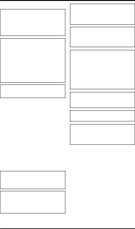
PRODUCT
IDENTIFICATION
 Grill
Grill
Plaque

 (behind
Grill)
Electronic
Ignitor
Manual/Auxiliary |
On/Pilot/Off Knob |
|
Knob |
||
|
Figure 1 - Infrared Tower Heater
UNPACKING
1.Remove heater from carton.
2.Remove all protective packaging applied to heater for shipment.
3.Check heater for any shipping damage. If heaterisdamaged,promptlycontactthedealer to where you bought heater.
PRODUCT FEATURES
SAFETY DEVICE
This heater has a pilot with an Oxygen Depletion Sensing (ODS) safety shutoff system. The ODS/pilot is a required feature for vent-free room heaters.The ODS/pilot shuts off the heater if there is not enough fresh air.
IGNITION SYSTEM
This heater has an electronic ignitor to light heater fuel supply, which requires a AAA battery.
THERMOSTATIC HEAT CONTROL
Your unit is thermostatically controlled when heater and remote control are set to the proper modes. This results in the greatest heater comfort.
4 |
www.desatech.com |
113261-01A |

AIR FOR COMBUSTION AND VENTILATION
 WARNING: This heater shall not be installed in a confined spaceorunusuallytightconstructionunlessprovisionsareprovided for adequate combustion and ventilationair.Readthefollowing instructionstoinsureproperfresh air for this and other fuel-burning appliances in your home.
Todayʼs homes are built more energy efficient than ever. New materials, increased insulation and new construction methods help reduce heat loss in homes. Home owners weather strip and caulk around windows and doors to keep the cold air out and the warm air in. During heating months, home owners want their homes as airtight as possible.
While it is good to make your home energy efficient, your home needs to breathe. Fresh air must enter your home.All fuel-burning appliances need fresh air for proper combustion and ventilation.
Exhaust fans, fireplaces, clothes dryers and fuel burning appliances draw air from the house to operate. You must provide adequate fresh air for these appliances. This will insure proper venting of vented fuel-burning appliances.
PROVIDING ADEQUATE VENTILATION
The following are excerpts from National Fuel Gas Code, ANSI Z223.1/NFPA 54, Section 5.3, Air for Combustion and Ventilation.
All spaces in homes fall into one of the three following ventilation classifications:
1.Unusually Tight Construction
2.Unconfined Space
3.Confined Space
The information on pages 5 through 7 will help you classify your space and provide adequate ventilation.
Unusually Tight Construction
The air that leaks around doors and windows may provide enough fresh air for combustion and ventilation. However, in buildings of unusually tight construction, you must provide additional fresh air.
Unusually tight construction is defined as construction where:
a.walls and ceilings exposed to the outside atmosphere have a continuous water vapor retarder with a rating of one perm (6 x 10-11 kg per pa-sec-m2) or less with openings gasketed or sealed and
b.weather stripping has been added on openable windows and doors and
c.caulking or sealants are applied to areas such as joints around window and door frames, between sole plates and floors, between wall-ceiling joints, between wall panels, at penetrations for plumbing, electrical and gas lines and at other openings.
If your home meets all of these three criteria, you must provide additional fresh air. See Ventilation Air From Outdoors, page 7.
If your home does not meet all of the three criteria above, proceed to Determining Fresh-Air Flow For Heater Location.
Confined and Unconfined Space
TheNationalFuelGasCode,ANSIZ223.1/NFPA54 defines a confined space as a space whose volume is less than 50 cubic feet per 1,000 Btu per hour (4.8 m3 per kw) of the aggregate input rating of all appliancesinstalledinthatspaceandanunconfined space as a space whose volume is not less than 50 cubic feet per 1,000 Btu/Hr (4.8 m3 per kw) of the aggregate input rating of all appliances installed in thatspace.Roomscommunicatingdirectlywiththe spaceinwhichtheappliancesareinstalled*,through openings not furnished with doors, are considered a part of the unconfined space.
* Adjoining rooms are communicating only if therearedoorless passagewaysorventilation grills between them.
DETERMINING FRESH-AIR FLOW FOR HEATER LOCATION
Determining if You Have a Confined or Unconfined Space
Use this work sheet to determine if you have a confined or unconfined space.
Space: Includes the room in which you will install heater plus any adjoining rooms with doorless passageways or ventilation grills between the rooms.
113261-01A |
www.desatech.com |
5 |
AIR FOR COMBUSTION AND VENTILATION
Continued
C.InstallalowerBtu/Hr(kw)heater,iflowerBtu/Hr (kw) size makes room unconfined.
If the actual Btu/Hr (kw) used is less than the maximum Btu/Hr (kw) the space can support, the space
1.Determine the volume of the space (length x is an unconfined space. You will need no additional
width x height).
Length x Width x Height =__________cu. ft. (volume of space)
Example: Space size 20 ft. (length) x 16 ft. (width) x 8 ft. (ceiling height) = 2560 cu. ft. (volume of space)
If additional ventilation to adjoining room is supplied with grills or openings, add the volume of these rooms to the total volume of the space.
2.Multiply the space volume by 20 to determine the maximum Btu/Hr (kw) the space can support.
__________ (volume of space) x 20 = (Maximum Btu/Hr the space can support)
Example: 2560 cu. ft. (volume of space) x 20 = 51,200 (maximum Btu/Hr the space can support)
3.Add the Btu/Hr (kw) of all fuel burning appliances in the space.
Vent-free heater |
________ Btu/Hr (kw) |
Gas water heater* |
________ Btu/Hr (kw) |
Gas furnace |
________ Btu/Hr (kw) |
Vented gas heater |
________ Btu/Hr (kw) |
Gas fireplace logs |
________ Btu/Hr (kw) |
Other gas appliances* +________ Btu/Hr (kw)
Total |
=________ Btu/Hr (kw) |
* Do not include direct-vent gas appliances. Di- rect-vent draws combustion air from the outdoors and vents to the outdoors.
Example: |
40,000 (11.7) |
|
Gas water heater |
Btu/Hr (kw) |
|
Vent-free heater |
+ 22,000 (6.4) |
Btu/Hr (kw) |
Total |
= 62,000 (18.2) |
Btu/Hr (kw) |
4.Compare the maximum Btu/Hr (kw) the space can support with the actual amount of Btu/Hr (kw) used.
___________Btu/Hr(kw) (maximumthespacecansupport)
___________Btu/Hr (kw) (actual amount of Btu/Hr used)
Example: 51,200 Btu/Hr (15 kw) (maximum the space can support)
62,000 Btu/Hr (18.2 kw) (actual amount of Btu/Hr used)
The space in the above example is a confined space because the actual Btu/Hr (kw) used is more than the maximum Btu/Hr (kw) the space can support. You must provide additional fresh air.Your options are as follows:
A.Reworkworksheet,addingthespaceofanadjoiningroom.Iftheextraspaceprovidesanunconfined space, remove door to adjoining room or add ventilation grills between rooms. See Ventilation Air From Inside Building.
B.Vent room directly to the outdoors. See Ventilation Air From Outdoors, page 7.
fresh air ventilation.
 WARNING:Iftheareainwhich the heater may be operated is smaller than that defined as an unconfined space or if the building is of unusually tight construction, provide adequate combustion and ventilation air byoneofthemethodsdescribed in the National Fuel Gas Code, ANSIZ223.1/NFPA54Section5.3 or applicable local codes.
VENTILATION AIR
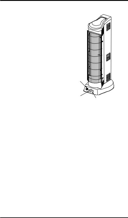
Ventilation Air From Inside Building
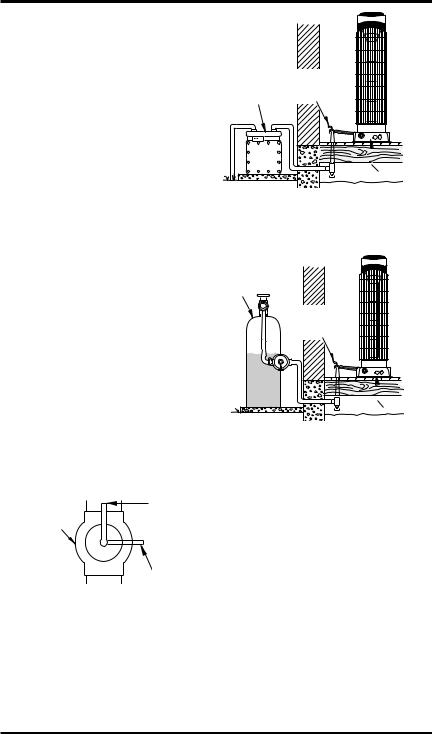
This fresh air would come from an adjoining unconfined space. When ventilating to an adjoining unconfined space, you must provide two permanent openings: one within 12" (30.5 cm) of the ceiling and one within 12" (30.5 cm) of the floor on the wall connecting the two spaces (see options 1 and 2, Figure 2). You can also remove door into adjoiningroom(seeoption3,Figure2).Followthe
National Fuel Gas Code, ANSI Z223.1/NFPA 54, Section5.3,AirforCombustionandVentilation for required size of ventilation grills or ducts.
|
12" (30,48 cm) |
|
Ventilation Grills |
Ventilation |
Into Adjoining Room, |
Option 2 |
|
Grills |
Or |
into Adjoining |
Remove |
Room, |
Door into |
Option 1 |
Adjoining |
|
Room, |
|
Option 3 |
|
12" (30,48 cm) |
Figure 2 - Ventilation Air from Inside Building
6 |
www.desatech.com |
113261-01A |
AIR FOR COMBUSTION
AND VENTILATION
Continued
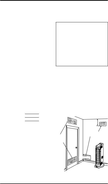
Ventilation Air From Outdoors
Provide extra fresh air by using ventilation grills or ducts. You must provide two permanent openings: one within 12" (30.5 cm) of the ceiling and one within 12" (30.5 cm) of the floor. Connect these items directly to the outdoors or spaces open to the outdoors. These spaces include attics and crawl spaces. Follow the National Fuel Gas Code, ANSI Z223.1/NFPA 54, Section 5.3, Air for Combustion and Ventilation for required size of ventilation grills or ducts.
IMPORTANT: Do not provide openings for inlet or outlet air into attic if attic has a thermostatcontrolled power vent. Heated air entering the attic will activate the power vent.
|
Outlet |
Ventilated |
|
Attic |
|
|
Air |
|
|
|
|
Outlet |
|
|
Air |
|
To Attic |
|
|
|
|
|
To |
|
|
Crawl |
Inlet |
|
Space |
|
|
|
Air |
|
|
|
Inlet Air |
Ventilated |
|
Crawl Space |
|
|
|
Figure 3 - Ventilation Air from Outdoors
INSTALLATION
NOTICE:Thisheaterisintended for use as supplemental heat. Use this heater along with your primary heating system. Do not install this heater as your primary heat source. If you have a centralheatingsystem,youmay run system’s circulating blower whileusingheater.Thiswillhelp circulatetheheatthroughoutthe house. In the event of a power outage, you can use this heater as your primary heat source.
 WARNING: A qualified service person must install heater. Follow all local codes.
CHECK GAS TYPE
Use only the correct type of gas (natural or propane/LP). If your gas supply is not the correct gas type, do not install heater. Call dealer where you bought heater for proper type heater.
 WARNING: This appliance is equipped for (natural or propane/LP) gas. Field conversion is not permitted.
INSTALLATION ITEMS
Before installing heater, make sure you have the items listed below.
•forpropane/LPgas,externalregulator(supplied by installer)
•piping (check local codes)
•sealant (resistant to propane/LP gas)
•equipment shutoff valve *
•ground joint union
•sediment trap
•tee joint
•pipe wrench
•for natural gas, test gauge connection*
*ACSAdesign-certified equipment shutoff valve with 1/8" NPT tap is an acceptable alternative to test gauge connection. The optional CSA designcertifiedequipmentshutoffvalvecanbepurchased from your dealer. See Accessories, page 22.
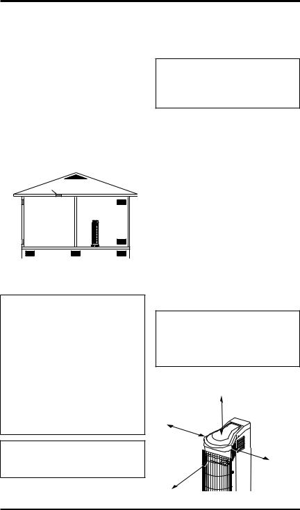
LOCATING HEATER
 WARNING: Maintain the minimum clearances shown in Figure 4. If you can, provide greater clearances from ceiling and joining wall(s).
Heater may be installed either in a corner or along the wall.
36"
(91.4 cm)
10" (25.4 cm)
36" |
10" |
|
(91.4 cm) |
||
(25.4 cm) |
||
|
Figure 4 - Clearances to Combustibles
113261-01A |
www.desatech.com |
7 |
INSTALLATION
Continued
 WARNING: Never install the heater
•in a bedroom or bathroom
•in a recreational vehicle
•where curtains, furniture, clothing or other flammable objectsarelessthan36inches (91.4 cm) from the front or top of the heater or less than 10" (25.4 cm) from sides of heater
•as a fireplace insert
•in high traffic areas
•in windy or drafty areas
 CAUTION: If you install the heater in a home garage
•heater pilot and burner must be at least 18 inches (45.7 cm) above floor
•locate heater where moving vehicle will not hit it
 CAUTION:Thisheatercreates warmaircurrents.Thesecurrents move heat to wall surfaces next to heater. Installing heater next tovinylorclothwallcoveringsor operatingheaterwhereimpurities (such as, but not limited to, tobacco smoke, aromatic candles, cleaning fluids, oil or kerosene lamps, etc.) in the air exist, may discolor walls or cause odors.
IMPORTANT: Vent-free heaters add moisture to the air.Although this is beneficial, installing heater in rooms without enough ventilation air may cause mildew to form from too much moisture. See Air forCombustionandVentilation, page5.Ifhighhumidity is experienced, a dehumidifier may be used to help lower the water vapor content in the air.
For convenience and efficiency, install heater
•where there is easy access for operation, inspection and service
•in coldest part of room
An optional fan kit is available from your dealer. See Accessories, page 22. If planning to use fan, locate heater near an electrical outlet.
INSTALLING REMOTE CONTROL RECEIVER
Remote control receiver must be installed to operate the remote control.
1.Locate receiver bracket, two packages of AA batteries, remote receiver and screws in hardware bag included with your heater.
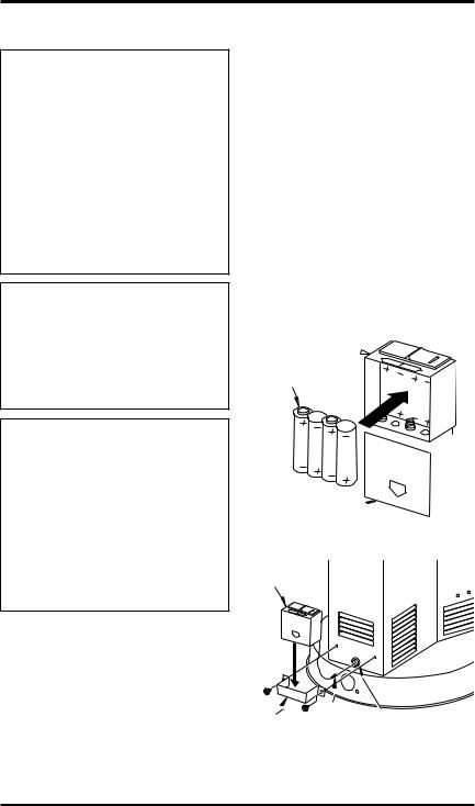
2.Remove battery cover on receiver and install batteries as showninFigure5.Replacebattery cover.
3.Insert wire connector and wire through bushing on the back of heater (see Figure 6).
4.Lay heater onto its side. Insert wire connector into valve at location shown in Figure 7 page 9. Feed extra wire from receiver into heater base. Place heater back in upright position.
5.Attach bracket around receiver with screws as shown in Figure 6.
Receiver 
AA Batteries
Battery Cover 
Figure 5 - Installing Batteries in Receiver
Receiver
Receiver |
Wire |
Bushing |
Connector |
|
|
Bracket |
|
|
|
|
|
Figure 6 - Installing Remote Receiver |
||
8 |
www.desatech.com |
113261-01A |

INSTALLATION
Continued
Bottom View
Receiver Wire |
Valve |
|
Figure 7 - Connecting Receiver Wire
INSTALLING BATTERIES INTO REMOTE
1.Locate hand-held remote control in hardware bag included with your heater.
2.Removebatterycoverandinsertsuppliedbatteries into remote control as shown in Figure 8.
3.Replace battery cover.
AAA
Batteries 
Remote Control
Battery Cover
Figure 8 - Installing Batteries in Hand-
Held Remote Control
ACTIVATING COMMUNICATION BETWEEN RECEIVER AND REMOTE CONTROL
1.Set receiver selector switch to the remote position (see Figure 9).
2.Push the ON button on hand-held remote control. You should hear a beep. If not, use a dull object to push the LEARN button in the receiver (see Figure 9). Push the ON button on remote control once again.You should hear a series of beeps.
If you have questions regarding the remote control or receiver, call 1-888-673-8929.
Slide Right to |
LEARN Button (Inside) |
||
REMOTE |
|||
|
|
||
|
F |
|
|
|
ROOM SET TEMP |
|
|
|
ON |
ON |
|
|
OFF |
||
|
MODE |
Button |
|
|
SET |
||
Figure 9 - Receiver and Remote Control |
|||
|
Setup |
|
|
REPLACING BATTERY IN IGNITOR
Ifthesparkthatlightsthepilotlessons,youmayneed to replace the battery in the ignitor. See Figure 10.
AAA Battery 
 Negative
  towards cap


Figure 10 - Replacing Battery in
Electronic Ignitor
MOUNTING HEATER BASE TO FLOOR (Where required by local codes)
1.Position heater indesired location. Mark holes for drilling. Move heater aside.
2.For carpeted floors, make a small cut with a sharp knife at the marked locations prior to drilling.
3.Drill 1/8" (diameter hole, 3/4" deep. (Do not use anchors in wood floors.)
4.Forconcretefloors,use1/4"diameterconcrete
drill bit. Drill 1 3/8" deep. Insert anchors completely into holes.
5.Positionheateroverholes.Securetofloorwith wood screws. See Figure 11.

 Wood
Wood
Screw

 Mounting Hole (One each side)
Figure 11 - Mounting Heater to Floor
113261-01A |
www.desatech.com |
9 |
INSTALLATION
Continued
CONNECTING TO GAS SUPPLY
 WARNING: This appliance requires a 3/8" NPT (National
PipeThread)inletconnectionto the pressure regulator.
 WARNING: A qualified service person must connect heater to gas supply. Follow all local codes.
 WARNING: For natural gas, neverconnectheatertoprivate (non-utility) gas wells. This gas is commonly known as wellhead gas.
IMPORTANT: For natural gas, check gas line pressure before connecting heater to gas line. Gas line pressure must be no greater than 10.5 inches (2.6 kPa) of water. If gas line pressure is higher, heater regulator damage could occur.
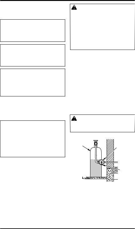
 CAUTION: For propane/LP gas, never connect heater directly to the propane/LP supply.
This heater requires an external regulator (not supplied). Install theexternalregulatorbetweenthe heater and propane/LP supply.
For propane/LP gas, the installer must supply an external regulator. The external regulator will reduce incoming gas pressure. You must reduce incominggaspressuretobetween11and14inches (2.7 and 3.5 kPa) of water. If you do not reduce incoming gas pressure, heater regulator damage could occur. Install the external regulator with the vent pointing down as shown in Figure 12. Pointing the vent down protects it from freezing rain or sleet.
CAUTION: Use only new, |
||||
black iron or steel pipe. Inter- |
||||
nally-tinned copper tubing may |
||||
be used in certain areas. Check |
||||
your local codes. Use pipe of |
||||
large enough diameter to allow |
||||
proper gas volume to heater. If |
||||
pipe is too small, undue loss of |
||||
volume will occur. |
|
|||
Typical Inlet Pipe Diameter |
||||
All models - 1/2" or greater |
||||
Installation must include equipment shutoff valve, |
||||
union and plugged 1/8" NPT tap. Locate NPT |
||||
tap within reach for test gauge hook up. NPT tap |
||||
must be upstream from heater (see Figure 13, |
||||
page 11). |
|
|||
IMPORTANT:Install an equipment shutoff valve |
||||
in an accessible location. The equipment shutoff |
||||
valve is for turning on or shutting off the gas to |
||||
the appliance. |
|
|||
Apply pipe joint sealant lightly to male NPT |
||||
threads. This will prevent excess sealant from |
||||
going into pipe. Excess sealant in pipe could result |
||||
in clogged heater valves. |
|
|||
WARNING: Use pipe joint |
||||
sealantthatisresistanttoliquid |
||||
petroleum (LP) gas. |
|
|||
Propane/LP |
External |
|||
Supply Tank |
||||
Regulator |
||||
|
|
|
||
|
|
|
||
Vent
Pointing
Down
Figure 12 - External Regulator With Vent
Pointing Down
10 |
www.desatech.com |
113261-01A |
INSTALLATION
Continued
Install sediment trap in supply line as shown in |
||||
Figure 13. Locate sediment trap where it is within |
||||
reach for cleaning. Locate sediment trap where |
||||
trapped matter is not likely to freeze. A sediment |
||||
trap traps moisture and contaminants. This keeps |
||||
them from going into heater controls. If sediment |
||||
trap is not installed or is installed wrong, heater |
||||
may not run properly. |
|
|||
IMPORTANT: Hold the pressure regulator with |
||||
wrench when connecting it to gas piping and/or |
||||
fittings. Do not over tighten pipe connection to |
||||
regulator. The regulator body could be damaged. |
||||
Pressure |
|
|
|
|
Regulator |
|
|
3/8" NPT |
|
Regulator |
|
|
||
|
|
Pipe |
||
Bracket |
|
|
Nipple |
|
Heater |
|
|
Ground |
|
Cabinet |
|
|
Joint |
|
Connection* |
|
|
|
Union |
Tee Joint |
|
Equipment |
||
|
|
|||
|
Reducer |
|
||
|
|
Shutoff |
||
|
Bushing to |
|
Valve * |
|
Gauge |
1/8" NPT |
|
|
|
1/8" NPT |
|
3" |
||
Test |
Plug Tap |
|
(76 mm) |
|
|
|
|
Min. |
|
|
|
|
|
|
|
Tee |
Pipe |
Cap |
Natural Gas |
|
Joint |
Nipple |
|
|
|
|
From Gas Meter |
||
|
|
|
|
|
|
Sediment Trap [7" (1.8 kPa) WC to |
|||
|
|
|
|
10.5" (2.6 kPa) WC |
|
|
|
|
Pressure] |
|
|
|
|
Propane/LP |
|
|
|
From External Regulator |
|
|
|
|
[11" (2.7 kPa) WC to 14" |
|
|
|
|
(3.5 kPa) WC Pressure] |
|
|
Figure 13 - Gas Connection |
|||
*ACSAdesign-certified equipment shutoff valve with 1/8" NPT tap is an acceptable alternative to test gauge connection. Purchase the optional CSA design-certifiedequipmentshutoffvalvefromyour dealer. See Accessories, page 22.
CHECKING GAS CONNECTIONS
 WARNING:Testallgaspiping and connections, internal and external to unit, for leaks after installing or servicing. Correct all leaks at once.
 WARNING:Neveruseanopen flame to check for a leak. Apply a noncorrosive leak detection fluid to all joints. Bubbles forming show a leak. Correct all leaks at once.
 CAUTION: For propane/LP gas, make sure external regulator has been installed between propane/LP supply and heater. See guidelines under Connecting to Gas Supply, page 10.
PRESSURE TESTING GAS SUPPLY PIPING SYSTEM
Test Pressures In Excess Of 1/2 PSIG (3.5 kPa)
1.Disconnect appliance with its appliance main gas valve (control valve) and equipment shutoff valve from gas supply piping system. Pressures in excess of 1/2 psig (3.5 kPa) will damage heater regulator.
2.Cap off open end of gas pipe where equipment shutoff valve was connected.
3.Pressurize supply piping system by either opening propane/LP supply tank valve for propane/LP gas or opening main gas valve located on or near gas meter for natural gas or using compressed air.
4.Check all joints of gas supply piping system. Apply a noncorrosive leak detection fluid to all joints. Bubbles forming show a leak.
5.Correct all leaks at once.
6.Reconnectheaterandequipmentshutoffvalveto gas supply. Check reconnected fittings for leaks.
113261-01A |
www.desatech.com |
11 |
INSTALLATION
Continued
Test Pressures Equal To or Less Than 1/2 PSIG (3.5 kPa)
1.Close equipment shutoff valve (see Figure 14).
2.Pressurize supply piping system by either opening propane/LP supply tank valve for propane/LP gas or opening main gas valve located on or near gas meter for natural gas or using compressed air.
3.Check all joints from gas meter for natural gas (see Figure 15) or propane/LPsupply tank for propane/LP gas, to equipment shutoff valve (see Figure 16). Apply a noncorrosive leak detection fluid to all joints. Bubbles forming show a leak.
4.Correct all leaks at once.
PRESSURE TESTING HEATER GAS CONNECTIONS
1.Open equipment shutoff valve (see Figure 14).
2.For natural gas open main gas valve located on or near gas meter. For propane/LPgas open propane/LP supply tank valve.
3.Make sure control knob of heater is in the OFF position.
4.Check all joints from equipment shutoff valve to thermostat gas valve (see Figure 15 or 16). Apply a noncorrosive leak detection fluid to all joints. Bubbles forming show a leak.
5.Correct all leaks at once.
6.Light heater (seeOperatingHeater, page 13). Check all other internal joints for leaks.
7.Turn off heater (see To Turn Off Gas to Appliance, page 14).
8.Replace front panel.
Equipment |
Open |
|
|
Shutoff Valve |
|
Equipment
Gas Shutoff
Meter Valve
Thermostat Gas Valve (Inside Heater)
Figure 15 - Checking Gas Joints for Natural Gas
Propane/LP
Supply Tank
Equipment
Shutoff
Valve
Thermostat Gas Valve
(Inside Heater)
Figure 16 - Checking Gas Joints for Propane/LP Gas
Closed
Figure 14 - Equipment Shutoff Valve
12 |
www.desatech.com |
113261-01A |
OPERATING HEATER
FOR YOUR SAFETY READ
BEFORE LIGHTING
 WARNING: If you do not follow these instructions exactly, a fire or explosion may result causing property damage, personal injury or loss of life.
A.This appliance has a pilot which must be lighted by hand. When lighting the pilot, follow these instructions exactly.
B.BEFORE LIGHTING smell all around the applianceareaforgas.Besuretosmellnext tothefloorbecausesomegasisheavierthan air and will settle on the floor.
WHAT TO DO IFYOU SMELL GAS
•Do not try to light any appliance.
•Do not touch any electric switch; do not use any phone in your building.
•Immediately call your gas supplier from a neighborʼs phone. Follow the gas supplierʼs instructions.
•If you cannot reach yourgas supplier, call the fire department.
C.Use only your hand to push in or turn the gas control knob. Never use tools. If the knobwillnotpushinorturnbyhand,donʼt try to repairit, call a qualified service technician or gas supplier. Force or attempted repair may result in a fire or explosion.
D.Do not use this appliance if any part has been under water. Immediately call a qualified service technician to inspect the appliance and to replace any part of the control system and any gas control which has been under water.
LIGHTING
INSTRUCTIONS
1.STOP! Read the safety information above.
2.Make sure equipment shutoff valve is fully open.
3.Turnpilotknobclockwise totheOFF position.
4.Waitfiveminutestoclearoutanygas.Then smellforgas,includingnearthefloor.Ifyou smell gas, STOP! Follow “B” in the safety information above. If you donʼt smell gas, go to the next step.
5.Press in pilot knob and turn counterclockwise  to the PILOT position. Keep pilot knob pressed in for five (5) seconds (see Figure 17).
Note: You may be running this heater for thefirsttimeafterhookinguptogassupply. If so, the pilot knob may need to be pressed in for 30 seconds or more. This will allow air to bleed from the gas system.
•If pilot knob does not pop up when released, contact a qualified service person or gas supplier for repairs.
6.With pilot knob pressed in, push in ignitor button. This will light pilot. The pilot is located at the bottom of plaque burners. If needed, keep pressing ignitor button until pilot lights.
Note: If pilot does not stay lit, refer to Troubleshooting, page 17. Also contact a qualified service person or gas supplier for repairs. Until repairs are made, light pilot with a match. To light pilot with a match, see Manual Lighting Procedure, page 14.
7.Keep pilot knob pressed in for 30 seconds afterlightingpilot.After30seconds,release pilot knob.
•If pilot knob does not pop up when released, contact a qualified service person or gas supplier for repairs.
Note: If pilot goes out, repeat steps 3 through 7.
8.With the auxiliary knob in the ON position, turn pilot knob counterclockwise  tostarttheheater.Themainburner should light.
|
|
|
AUX |
T |
ON |
|
|
|
N |
O |
|
||
|
|
N |
O |
|
||
|
|
O |
I |
|
||
|
|
|
|
L |
|
|
|
|
|
A |
P |
O |
|
|
|
|
|
|||
|
|
|
XU |
|
FF |
|
Electronic |
Ignitor |
Auxiliary |
Pilot |
|||
Knob |
Knob |
|||||
Button |
||||||
|
|
|
|
|||
Figure 17 - Pilot Knob In The ON Position |
||||||
|
|
Thermocouple |
|
|
||
Ignitor Electrode
Pilot
 Burner
Figure 18 - Pilot
113261-01A |
www.desatech.com |
13 |
OPERATING HEATER
Continued
9.With the auxiliary knob in the AUX position, push the ON button on the remote control.To adjust the temperature with the remote control, follow the instructions on page 15. When the temperature surrounding the remote control drops below the set temperature, the burner should light. The remote receiver behind the unit must be in the REMOTE position.
 CAUTION: Do not try to adjust heating levels by using the equipment shutoff valve.
TO TURN OFF GAS TO APPLIANCE
Shutting Off Heater
1.Press in and turn pilot knob clockwise  to the OFF position.
2.Unplug any electrical power to the appliance if service is to be performed.
Shutting Off Burner Only (pilot stays lit) |
|
If auxiliary knob is inAUX position, push OFF |
|
button on remote control. |
|
If auxiliary knob is in ON position, turn pilot |
|
knob clockwise |
to the PILOT position. |
THERMOSTAT OPERATION
The thermostat used on this heater senses the room temperature at the location of the handheld remote control. At times the room may exceedthesettemperature.Ifso,theburnerwill shut off. The burner will cycle back on when roomtemperaturedropsbelowthesettemperature. All plaques will turn off and on.
MANUAL LIGHTING PROCEDURE
1.Follow steps 1 through 5 under Lighting Instructions, page 13.
2.With pilot knob pressed in, strike match. Hold match to pilot until pilot lights.
3.Keep pilot knob pressed in for 30 seconds afterlightingpilot.After30seconds,release pilot knob. Continue with step 8 under
Lighting Instructions, above.
HAND-HELD REMOTE
CONTROL OPERATION
1.Slide selector switch on remote receiver to the REMOTE position.
2.Slightly pull and turn auxiliary knob so the AUX is to the left and right and ON is to the top and bottom positions.
3.Light the pilot. Follow steps 1 through 6 under Lighting Instructions, page 13.
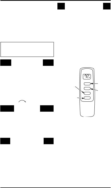
DISPLAY
The LCD display on the remote control indicates current room temperature in Fahrenheit or Celsius. The small flame indicates burner/ valve in operation. ROOM indicates remote is in thermo operation. TEMP appears during manual operation. SET appears during the time of setting the desired temperature in the thermo operation.
|
F |
|
Changes heater |
ROOM SET TEMP |
Turns |
|
||
from Manual |
ON |
heater |
Mode to |
|
ON |
Thermo Mode |
OFF |
|
Sets |
|
Turns |
MODE |
heater |
|
temperature in |
SET |
OFF |
Thermo Mode |
|
|
Figure 19 - Hand-Held Remote Control Unit
SETTING FAHRENHEIT AND CELSIUS SCALE The factory setting for temperature is Fahrenheit. To change this setting to Celsius, press the ON and OFFbuttons on remote at the same time.Followthesameproceduretochangefrom Celsius back to Fahrenheit.
MANUAL FUNCTION
On Operation When the ON button is pressed the appliance flame will come on. The LCD screen will show ON for three seconds, then default to room temperature and the word TEMP and flame icon will show.
Off Operation When the OFF button is pressed the appliance flame will shut off. The LCD screen will show OFforthreeseconds,thendefaulttoroomtemperature and the word TEMP will show.
14 |
www.desatech.com |
113261-01A |
OPERATING HEATER Continued
THERMOSTAT FUNCTION
Setting Desired Room Temperature This remote control system can be thermostatically controlled when the remote control is in the thermo mode. The word ROOM must be displayed on the screen.
1.PressMODEbuttononremotecontroluntil ROOMappears.Thissetstheremotetothe thermostat mode.
2.Press and hold the SET button until the desired temperature is displayed. The numbers will increase from 45° to 99° then restart over at 45°.After releasing the SET button, the set room temperature will display for 3 seconds, then default to display the room temperature.
Changing Set Temperature
1.FollowsteptwounderSettingDesiredRoom Temperature above.
2.Press the MODE button to disengage the thermo mode. The word ROOM does not display when thermo mode is not in operation.
INSPECTING HEATER
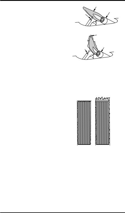
Check pilot flame pattern and burner flame pattern often.
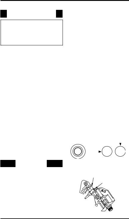
PILOT FLAME PATTERN
Figure 20 shows a correct pilot flame pattern. Figure 21 shows an incorrect pilot flame pattern. The incorrect pilot flame is not touching the thermocouple. This will cause the thermocouple to cool. When the thermocouple cools, the heater will shut down.
If pilot flame pattern is incorrect, as shown in Figure 21
•turn heater off (see To Turn Off Gas to Appliance, page 14)
•see Troubleshooting, page 17
Note: The pilot flame on natural gas units will have a slight curve, but flame should be blue and have no yellow or orange color.
Blue Flame
Pilot Burner
Thermocouple
Figure 20 - Correct Pilot Flame Pattern |
|
|
Yellow Flame |
Thermocouple |
Pilot Burner |
|
|
Figure 21 - Incorrect Pilot Flame Pattern |
|
BURNER FLAME PATTERN |
|
Figure22showsacorrectandincorrectburnerflame |
|
pattern. If burner flame pattern is incorrect |
|
•turn heater off (see To Turn Off Gas to Appliance, page 14)
•see Troubleshooting, page 17
Correct |
Incorrect |
Flame |
Flame |
Pattern |
Pattern |
Figure 22 - Burner Operation
113261-01A |
www.desatech.com |
15 |
Loading...