


VSGF36NT
Table of contents
 Loading...
UNVENTED (VENT-FREE) UNIVERSAL FIREBOX
OWNER’S OPERATION AND INSTALLATION MANUAL
MODELS
VSGF36NT, VSGF36PT, VSGF36NR AND VSGF36PR
WARNING: If the information in this manual is not followed exactly, a fire or explosion may result causing
property damage, personal injury or loss of life.
— Do not store or use gasoline or other flammable
vapors and liquids in the vicinity of this or any other
appliance.
— WHAT TO DO IF YOU SMELL GAS
• Do not try to light any appliance.
• Do not touch any electrical switch; do not use any
phone in your building.
• Immediately call your gas supplier from a neighbor’s
phone. Follow the gas supplier’s instructions.
• If you cannot reach your gas supplier, call the fire
department.
— Installation and service must be performed by a quali-
fied installer, service agency or the gas supplier.
Save this manual for future reference.
For more information, visit www.desatech.com
WARNING: Improper installation, adjustment, alteration, service or maintenance can cause injury or property damage. Refer to this manual for correct installation
and operational procedures. For assistance or additional information consult a qualified installer, service
agency or the gas supplier.
WARNING: This is an unvented gas-fired heater. It uses
air (oxygen) from the room in which it is installed. Provisions for adequate combustion and ventilation air must
be provided. Refer to Air for Combustion and Ventilation
section on page 7 of this manual.
WARNING: For use only with a listed decorative type
unvented room heater. Do not build a wood fire.
This firebox has been tested and approved by CSA International under Z21.91-2001 for use with approved ANSI
Z21.11.2 decorative type unvented room heater.
This appliance may be installed in an aftermarket*, permanently located, manufactured (mobile) home, where
not prohibited by local codes.
This appliance is only for use with the type of gas indicated on the rating plate. This appliance is not convertible for use with other gases.
*Aftermarket: Completion of sale, not for purpose of resale, from the manufacturer
TABLE OF CONTENTS
Safety Information ............................................... 3
Local Codes ........................................................ 4
Product Identification ........................................... 5
Unpacking ........................................................... 5
Product Features ................................................. 5
Locating Firebox .................................................. 6
Product Specifications ......................................... 6
Air For Combustion and Ventilation ..................... 7
Installation ........................................................... 9
Operating Fireplace ........................................... 19
Inspecting Burners ........................................... 24
2
www.desatech.com
Cleaning and Maintenance ................................ 25
Wiring Diagram .................................................. 26
Specifications .................................................... 26
Replacement Parts ............................................ 26
Technical S
Service Hints ..................................................... 26
Troubleshooting ................................................. 27
Accessories ....................................................... 31
Illustrated Parts Breakdown and Parts List ....... 32
Warranty Information ...........................
ervice .............................................. 26
Back Cover
113192-01B
SAFETY INFORMATION
WARNING: This product contains and/or generates chemicals
known to the state of California
to cause cancer or birth defects
or other reproductive harm.
IMPORTANT: Read this owner’s
manual carefully and completely
be f o r e tr y i n g to assemb l e ,
operate or service this heater.
Improper use of this heater can
cause serious injury or death
from burns, fire, explosion,
electrical shock and carbon
monoxide poisoning.
DANGER: Carbon monoxide
poisoning may lead to death!
Carbon Monoxid e Poiso nin g: Early signs of
carbon monoxide poisoning resemble the flu, with
headaches, dizziness or nausea. If you have these
signs, the heater may not be working properly. Get
fresh air at once! Have heater serviced. Some
people are more affected by carbon monoxide than
others. These include pregnant women, people with
heart or lung disease or anemia, those under the
influence of alcohol and those at high altitudes.
Natural and Propane/LP Gas: Natural and pro-
pane/LP gases are odorless. An odor-making agent
is added to the gas. The odor helps you detect a gas
leak. However, the odor added to the gas can fade.
Gas may be present even though no odor exists.
Make certain you read and understand all warnings.
Keep this manual for reference. It is your guide to
safe and proper operation of this heater.
WARNING: Do not allow fans
to blow directly into the fireplace.
Avoid any drafts that alter burner
flame patterns. Ceiling fans can
create drafts that alter burner
flame patterns. Altered burner
patterns can cause sooting.
Due to high temperatures, the
appliance should be located out
of traffic and away from furniture
and draperies.
Do not place clothing or other
flammable material on or near
the appliance. Never place any
objects on the heater.
Fireplace front and screen be
come very hot when running fire
place. Keep children and adults
away from hot surfaces to avoid
burns or clothing ignition. Fireplace will remain hot for a time
after shutdown. Allow surfaces
to cool before touching.
Carefully supervise young children when they are in the room
with fireplace. When using the
optional hand-held remote ac
cessory, keep selector switch
in the OFF position to prevent
children from turning on burners
with remote.
-
-
-
WARNING: Any change to
this heater or its controls can
be dangerous.
WARNING: Do not use a
blower insert, heat exchanger
insert or other accessory not ap
proved for use with this heater.
113192-01B
www.desatech.com
You must operate this fireplace
with the fireplace screen and
hood in place. Make sure fireplace screen and hood are in
place before running heater.
-
Keep the appliance area clear
and free from combustible materials, gasoline and other flammable vapors and liquids.
3

SAFETY INFORMATION
Continued
1.
This appliance is only for use with the type of
gas indicated on the rating plate. This appliance
is not convertible for use with other gases.
2. Do not place propane/LP supply tank(s) inside any structure. Locate propane/LP supply
tank(s) outdoors (propane/LP units only).
3. If you smell gas
• shut off gas supply
• do not try to light any appliance
• do not touch any electrical switch; do not use
any phone in your building
• immediately call your gas supplier from a
neighborʼs phone. Follow the gas supplierʼs
instructions
• if you cannot reach your gas supplier, call
the fire department
4. This fireplace shall not be installed in a bed
room or bathroom.
5. Do not use this fireplace as a wood-burning
fireplace. Use only the logs provided with the
fireplace.
6. Do not add extra logs or ornaments such as
pine cones, vermiculite or rock wool. Using
these added items can cause sooting. Do not
add lava rock around base. Rock and debris
could fall into the control area of fireplace.
7. To prevent the creation of soot, follow the
instructions in Cleaning and maintenance
page 25.
8. Before using furniture polish, wax, carpet
cleaner or similar products, turn heater off. If
heated, the vapors from these products may
create a white powder residue within burner
box or on adjacent walls or furniture.
9. This fireplace needs fresh air ventilation to run
properly. This fireplace has an Oxygen Deple
tion Sensing (ODS) safety shutoff system. The
ODS shuts down the fireplace if enough fresh
air is not available. See Air for Combustion
and Ventilation, page 7. If fireplace keeps
shutting off, see Troubleshooting, page 27.
10. Do not run fireplace
• where flammable liquids or vapors are used
or stored
• under dusty conditions
11. Do not use this fireplace to cook food or burn
paper or other objects.
12. Do not use fireplace if any part has been
exposed to or under water. Immediately call
a qualified service technician to inspect the
fireplace and to replace any part of the control
system and any gas control which has been
under water.
13. Do not operate fireplace if any log is broken.
Do not operate fireplace if a log is chipped
(dime-sized or larger).
14. Turn fireplace off and let cool before servicing.
Only a qualified service person should service
and repair fireplace.
15. Operating fireplace above elevations of 4,500
feet could cause pilot outage.
16.
To prevent performance problems in propane/LP
units, do not use propane/LP fuel tanks of less
than 100 lbs. capacity (propane/LP units only).
17.
Provide adequate clear ances around a ir
openings.
-
LOCAL CODES
Install and use fireplace with care. Follow all local
codes. In the absence of local codes, use the latest edition of The National Fuel Gas Code ANSI
Z223.1/NFPA 54*.
*Available from:
American National Standards Institute, Inc.
National Fire Protection Association, Inc.
,
Note: Where listed vented decorative logs are
required, thermostat operation is not permitted.
State of Massachusetts: The installation must be made by a licensed plumber
or gas fitt er in the Common we alth of
-
Massachusetts.
Sel lers of unvented propane or natural
gas-fired supplemental room heaters shall
provide to each purchaser a copy of 527
CMR 30 upon sale of the unit.
Vent-free gas products are prohibited for
bedroom and bathroom installation in the
Commonwealth of Massachusetts.
1430 Broadway
New York, NY 10018
Batterymarch Park
Quincy, MA 02269
4
www.desatech.com
113192-01B
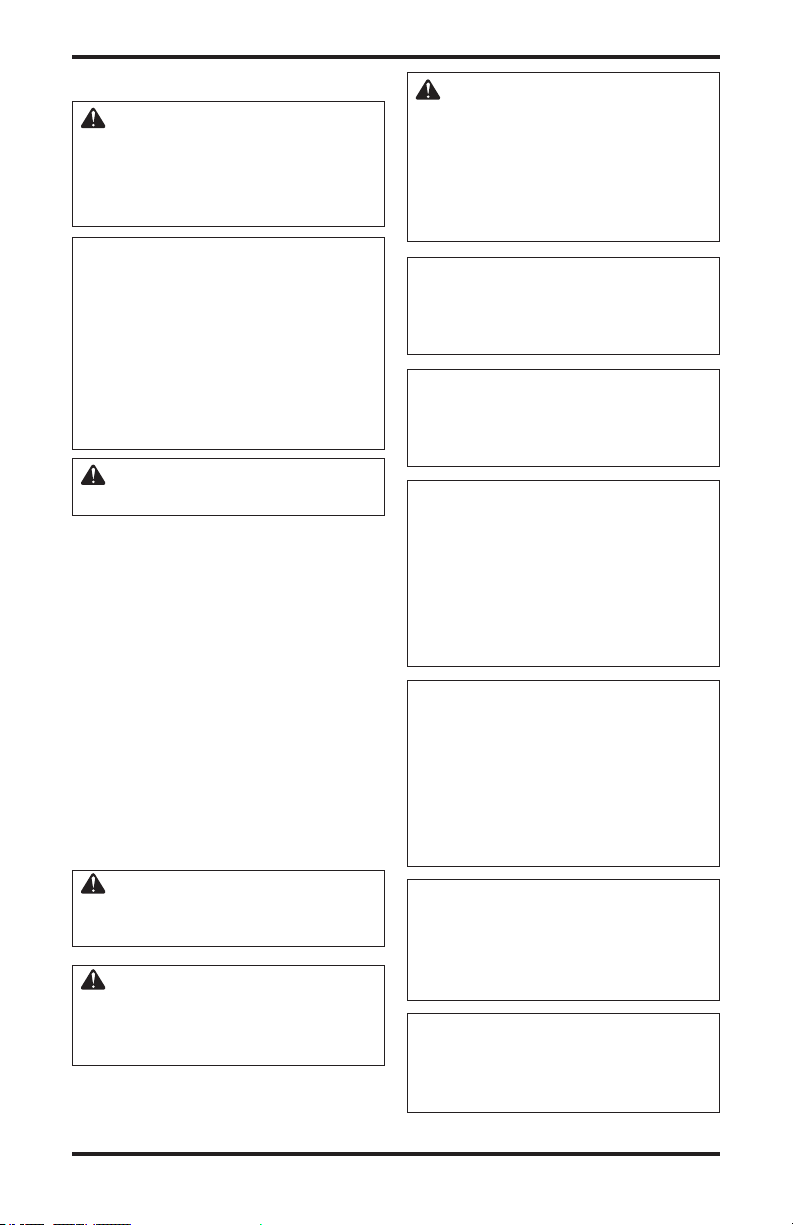
PRODUCT
IDENTIFICATION
Log Set
Piezo
Ignitor
Optional
Remote Control
Figure 1 - Log Base Assembly
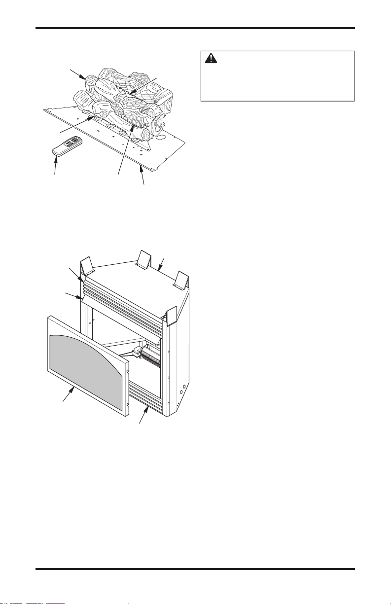
Top Louver
Assembly
Fireplace
Hood
Screen
Assembly
Figure 2 - Fireplace (VSGF36NR Shown)
Front
Burner
(VSGF36NR Shown)
Bottom Louver
Assembly
Rear
Burner
Base
Assembly
Top Outer
Casing
UNPACKING
CAUTION: Do not remove
the data plates attached to the
heater base assembly. The data
plates contain
1. With utility knife, cut the carton all the way
around above the staples on the bottom tray.
Lift the carton off the heater. Remove packing.
Note: The hood is located on top of fireplace
in a carton.
Locate one screw above top left corner of the
2.
fireplace screen. Remove and discard screw. Lift
fireplace screen up and pull out to remove.
3. Remove protective packaging applied to logs,
log base assembly and fireplace.
4. Check all items for any shipping damage. If
damaged, promptly inform dealer where you
bought fireplace.
PRODUCT FEATURES
OPERATION
This vent-free fireplace is clean burning. It requires
no outside venting. There is no heat loss out a vent
or up a chimney. Heat is generated by both realistic
flames and glowing embers. When used without the
blower, the fireplace requires no electricity making
it ideal for emergency backup heat.
SAFETY DEVICE
This fireplace has a pilot with an Oxygen Depletion
Sensing (ODS) safety shutoff system. The ODS/
pilot is a required feature for vent-free room heaters. The ODS/pilot system shuts off the fireplace
if there is not enough fresh air.
PIEZO IGNITION SYSTEM
This fireplace has a piezo ignitor. This system
requires no matches, batteries or other sources to
light fireplace.
OPTIONAL REMOTE CONTROL
ACCESSORY
There are four optional remote controls (not
included) that can be purchased separately for
this log heater:
• wall switch
• wall thermostat
• hand-held ON/OFF remote
• hand-held thermostat remote
See Accessories, page 31.
113192-01B
www.desatech.com
5
LOCATING FIREBOX
PLANNING
Plan where you will install the firebox. This will save time and money later when you install the firebox.
Before installation, consider the following:
1. Where the firebox will be located. Allow for wall and ceiling clearances (see Installation Clear
ances, page 10).
2. Everything needed to complete installation.
3. These models CANNOT be installed in a bedroom unless the maximum Btu rating of the installed
vent-free log set is less than 10,000 Btu/hr.
4. Proper air for combustion and ventilation (page 7).
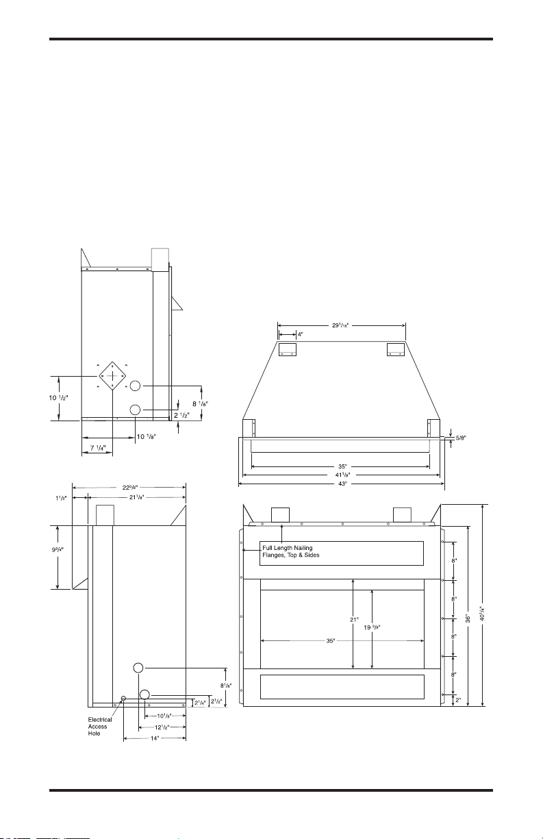
PRODUCT SPECIFICATIONS
Left Side View
Firebox Top View
-
Right Side View
Front View
Figure 3 - Firebox Dimensions
6
www.desatech.com
113192-01B

AIR FOR COMBUSTION
AND VENTILATION
WARNING: This firebox shall
not be installed in a confined
space or unusually tight construction unless provisions are
provided for adequate combustion and ventilation air. Read the
following instructions to insure
proper fresh air for this and
other fuel-burning appliances
in your home.
Todayʼs homes are built more energy efficient
than ever. New materials, increased insulation and
new construction methods help reduce heat loss
in homes. Home owners weather strip and caulk
around windows and doors to keep the cold air out
and the warm air in. During heating months, home
owners want their homes as airtight as possible.
While it is good to make your home energy effi
cient, your home needs to breathe. Fresh air must
enter your home. All fuel-burning appliances need
fresh air for proper combustion and ventilation.
Exhaust fans, fireboxes, clothes dryers and fuel
burning appliances draw air from the house to
operate. You must provide adequate fresh air for
these appliances. This will insure proper venting
of vented fuel-burning appliances.
PROVIDING ADEQUATE
VENTILATION
The following are excerpts from National Fuel
Gas Code, ANSI Z223.1/NFPA 54, Section 5.3,
Air for Combustion and Ventilation.
All spaces in homes fall into one of the three fol
lowing ventilation classifications:
1. Unusually Tight Construction
2. Unconfined Space
3. Confined Space
The information on pages 7 through 9 will help
you classify your space and provide adequate
ventilation.
Unusually Tight Construction
The air that leaks around doors and windows
may provide enough fresh air for combustion and
ventilation. However, in buildings of unusually
tight construction, you must provide additional
fresh air.
Unusually tight construction is defined as
construction where:
a. walls and ceilings exposed to the out
side atmosphere have a continuous
water vapor retarder with a rating of
one perm (6 x 10
less with openings gasketed or sealed
and
b. weather stripping has been added on
openable windows and doors and
c. caulking or sealants are applied to
areas such as joints around window
and door frames, between sole plates
and floors, between wall-ceiling joints,
between wall panels, at penetrations
for plumbing, electrical and gas lines
and at other openings.
If your home meets all of the three criteria
above, you must provide additional fresh
air. See Ventilation Air From Outdoors
page 9.
If your home does not meet all of the three
criteria above, proceed to Determining
-
Fresh-Air Flow for Heater Location, page 8.
Confined and Unconfined Space
The National Fuel Gas Code, ANSI Z223.1/NFPA
54 defines a confined space as a space whose
volume is less than 50 cubic feet per 1,000 Btu
per hour (4.8 m
rating of all appliances installed in that space and
an unconfined space as a space whose volume is
not less than 50 cubic feet per 1,000 Btu per hour
3
(4.8 m
per kw) of the aggregate input rating of
all appliances installed in that space. Rooms com
municating directly with the space in which the
appliances are installed*, through openings not
furnished with doors, are considered a part of the
unconfined space.
* Adjoining rooms are communicating only if
there are doorless passageways or ventilation grills
between them.
-11
kg per pa-sec-m2) or
3
per kw) of the aggregate input
-
,
-
113192-01B
www.desatech.com
7
AIR FOR COMBUSTION
AND VENTILATION
Continued
DETERMINING FRESH-AIR FLOW
FOR HEATER LOCATION
Determining if You Have a Confined or
Unconfined Space
Use this work sheet to determine if you have a
confined or unconfined space.
Space: Includes the room in which you will
install heater plus any adjoining rooms with door
less passageways or ventilation grills between
the rooms.
1. Determine the volume of the space (length x
width x height).
Length x Width x Height =__________cu. ft.
(volume of space)
Example: Space size 22 ft. (length) x 18 ft.
(width) x 8 ft. (ceiling height) = 3168 cu. ft.
(volume of space)
If additional ventilation to adjoining room is
supplied with grills or openings, add the volume
of these rooms to the total volume of the space.
2. Multiply the space volume by 20 to determine
the maximum Btu/Hr the space can support.
__________ (volume of space) x 20 = (Maxi-
mum Btu/Hr the space can support)
Example: 3168 cu. ft. (volume of space) x 20 =
63,360 (maximum Btu/Hr the space can support)
3. Add the Btu/Hr of all fuel burning appliances in
the space.
Vent-free fireplace ___________
Gas water heater* ___________
Gas furnace ___________
Vented gas heater ___________
Gas fireplace logs ___________
Other gas appliances* + __________
Total = __________
* Do not include direct-vent gas appliances. Di
rect-vent draws combustion air from the outdoors
and vents to the outdoors.
Example:
Gas water heater
Vent-free fireplace + ________
Total = ________
40,000
__________ Btu/Hr
39,000
79,000
Btu/Hr
Btu/Hr
Btu/Hr
Btu/Hr
Btu/Hr
Btu/Hr
Btu/Hr
Btu/Hr
Btu/Hr
4. Compare the maximum Btu/Hr the space can
support with the actual amount of Btu/Hr used.
_________
_________
Example: 63,360 Btu/Hr (maximum the space
79,000 Btu/Hr (actual amount of
The space in the above example is a confined space
because the actual Btu/Hr used is more than the maxi
mum Btu/Hr the space can support. You must provide
additional fresh air. Your options are as follows:
-
A. Rework worksheet, adding the space of an adjoin
ing room. If the extra space provides an unconfined
space, remove door to adjoining room or add
ventilation grills between rooms. See Ventilation
Air From Inside Building, page 9.
B. Vent room directly to the outdoors. See Ventila
tion Air From Outdoors, page 9.
C. Install a lower Btu/Hr fireplace, if lower Btu/Hr
size makes room unconfined.
Btu/Hr (maximum the space can support)
Btu/Hr (actual amount of Btu/Hr used)
can support)
Btu/Hr used)
If the actual Btu/Hr used is less than the maximum Btu/Hr the space can support,
the space is
an unconfined space. You will need no additional
fresh air ventilation.
WARNING: If the area in which
the heater may be operated is
smaller than that defined as
an unconfined space or if the
building is of unusually tight
construction, provide adequate
combustion and ventilation air
by one of the methods described
in the National Fuel Gas Code,
ANSI Z223.1/NFPA 54 Section 5.3
or applicable local codes.
-
-
-
-
8
www.desatech.com
113192-01B
AIR FOR COMBUSTION
Or
Remove
Door into
Adjoining
Room,
Option
3
Ventilation Grills
Into Adjoining Room,
Option
2
Ve
ntilation
Grills
Into Adjoining
Room,
Option 1
12"
12"
Outlet
Air
Ve
ntilated
Attic
Outlet
A
ir
Inlet
Air
Inlet Air
Ve
ntilated
Crawl Space
To
Crawl
Space
To Attic
AND VENTILATION
Continued
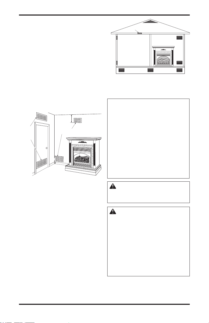
VENTILATION AIR
Ventilation Air From Inside Building
This fresh air would come from an adjoining un
confined space. When ventilating to an adjoining
unconfined space, you must provide two perma-
nent openings: one within 12" of the ceiling and
one within 12" of the floor on the wall connecting
the two spaces (see options 1 and 2, Figure 4). You
can also remove door into adjoining room (see
option 3, Figure 3). Follow the National Fuel Gas
Code, ANSI Z223.1/NFPA 54, Section 5.3, Air for
Combustion and Ventilation for required size of
ventilation grills or ducts.
-
Figure 5 - Ventilation Air from Outdoors
INSTALLATION
NOTICE: This heater is intended
for use as supplemental heat.
Use this heater along with your
primary heating system. Do not
install this heater as your pri
mary heat source. If you have a
central heating system, you may
run system’s circulating blower
while using heater. This will help
circulate the heat throughout the
house. In the event of a power
outage, you can use this heater
as your primary heat source.
-
Figure 4 - Ventilation Air from Inside
Building
Ventilation Air From Outdoors
Provide extra fresh air by using ventilation grills or
ducts. You must provide two permanent openings:
one within 12" of the ceiling and one within 12"
of the floor. Connect these items directly to the
outdoors or spaces open to the outdoors. These
spaces include attics and crawl spaces. Follow the
National Fuel Gas Code, ANSI Z223.1/NFPA 54,
Section 5.3, Air for Combustion and Ventilation for
required size of ventilation grills or ducts.
IMPORTANT: Do not provide openings for inlet
or outlet air into attic if attic has a thermostat-
controlled power vent. Heated air entering the attic
will activate the power vent.
113192-01B
www.desatech.com
WARNING: A qualified service
person must install fireplace.
Follow all local codes.
WARNING: Never install the
fireplace
• in a bedroom or bathroom
• in a recreational vehicle
• where curtains, furniture,
clothing or other flammable
objects are less than 42 inches
from the front, top or sides of
the heater
• in high traffic areas
• in windy or drafty areas
9
INSTALLATION
Continued
CAUTION: This fireplace creates warm air currents. These
currents move heat to wall sur
faces next to fireplace. Installing
fireplace next to vinyl or cloth
wall coverings or operating
heater where impurities (such
as, but not limited, to tobacco
smoke, aromatic candles, cleaning fluids, oil or kerosene lamps,
etc.) in the air exist, may discolor
walls or cause odors.
Note: Your fireplace is designed to be used in zero
clearance installations. Wall or framing material
can be placed directly against any exterior surface
on the rear, sides or top of your fireplace, except
where standoff spacers are integrally attached. If
standoff spacers are attached to your fireplace,
these spacers can be placed directly against wall
or framing materials.
Use the dimensions shown for rough openings to
create the easiest installation. See Built-In Fire
place Installation, page 11.
IMPORTANT: Vent-free heaters add moisture to
the air. Although this is beneficial, installing fire
place in rooms without enough ventilation air may
cause mildew to form from too much moisture. See
Air for Combustion and Ventilation
IMPORTANT: Make sure the fireplace is level.
If fireplace is not level, log set will not work
properly.
CHECK GAS TYPE
Use the correct gas type (natural or propane/LP)
for your fireplace. If your gas supply is not correct, do not install fireplace. Call dealer where you
bought fireplace for proper type fireplace.
, page 7.
-
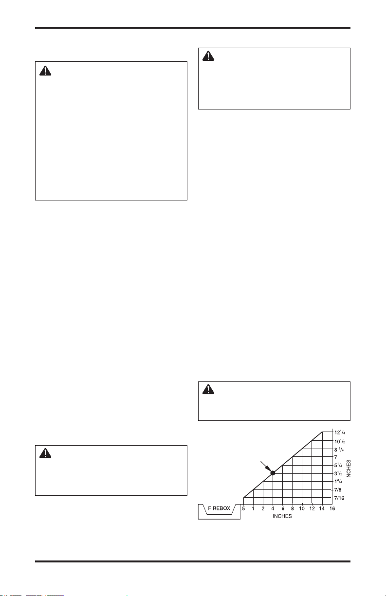
INSTALLATION CLEARANCES
WARNIN G: Maintain the
minimum clearances. If you
can, provide greater clearances
from floor, ceiling and adjoining
wall.
Carefully follow the instructions below. This will
ensure safe installation.
Minimum Wall and Ceiling Clearances (see
Figure 6)
A. Clearances from the side of the fireplace
cabinet to any combustible material and wall
should follow diagram in Figure 6.
Example: The face of a mantel, bookshelf,
etc. is made of combustible material and
protrudes 3 1/2" from the wall. This combustible material must be 4" from the side of the
fireplace cabinet (see Figure 6).
B. Clearances from the top of the firebox open
ing to the ceiling should not be less than 42
inches.
C. When the firebox is installed on carpeting or
other combustible material, other than wood
flooring, the firebox should be installed on a
metal or wood panel extending the full width
-
and depth of the enclosure.
D. Clearances from the bottom of firebox to the
floor is 0 inches.
These fireboxes can be installed as freestanding
units against a wall with the approved, optional
cabinet mantels (see
built-in unit. The clearances are the same for either
installation method.
Accessories, page 31) or as a
CAUTION: Do not install the
firebox directly on carpet or
vinyl.
-
WARNING: This appliance
is equipped for (natural or propane/LP) gas. Field conversion
is not permitted.
10
www.desatech.com
Example
*
*Minimum 16 inches from Side Wall
Figure 6 - Minimum Clearance for
Combustible to Wall
113192-01B
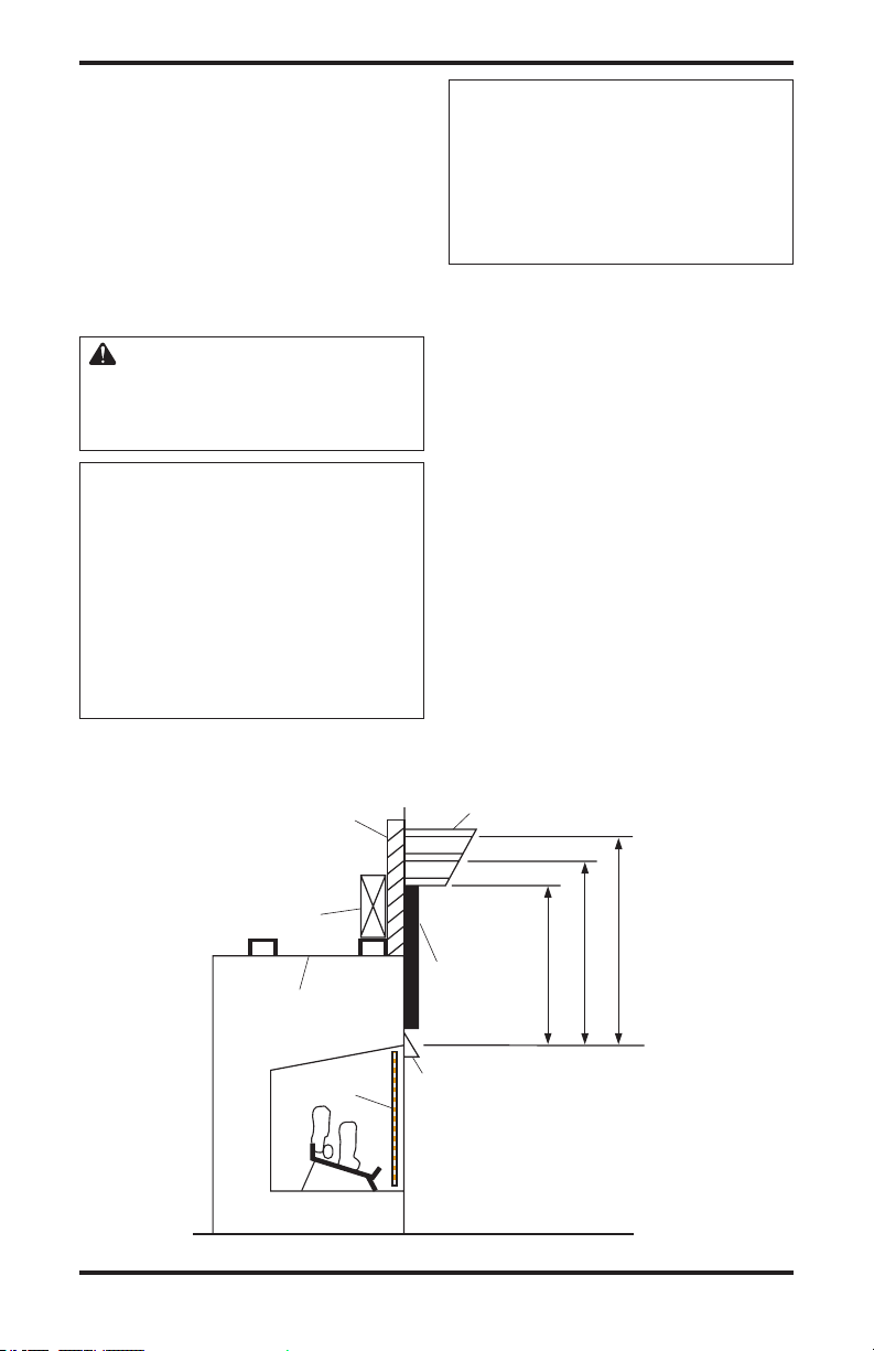
INSTALLATION
Supplied Firebox
Hood Must Be
Used at All Times
Wire-mesh
Screen
Firebox
Noncombustible
Material May
Project Off this
Surface above
the Firebox Hood
Mantel Shelf
Note: Any portion of the
mantel shelf must NOT
extend beyond this profile.
12"
16"
20"
1
1
/
2
"
6
3
/
4
"
12"
Note: All vertical
measurements are
from top of fireplace
hood opening to
bottom of mantel shelf.
These minimum
clearances replace any
other recommended
clearances supplied with
your ANSI Z21.11.2
approved gas logs.
Wa
ll board or facing
material (above
firebox) may be of
combustible material,
including decorative
mantel ornaments or
other similar projections off of the facing
material.
Framing
Material
Continued
Mantel Clearances for Built-In
Installation
If placing custom mantel above built-in firebox,
you must meet the minimum allowable clearance
between mantel shelf and top of firebox opening
shown in Figure 7. These are the minimum allowable
mantel clearances for a safe installation. Use larger
clearances wherever possible to minimize the heating of objects and materials placed on the mantel.
CAUTION: Do not allow the
vent-free gas log heater to touch
or extend beyond the fireplace
screen.
NOTICE: Surface temperatures
of adjacent walls and mantels become hot during operation. Walls
and mantels above the firebox
may become hot to the touch.
If installed properly, these temperatures meet the requirement
of the national product standard.
Follow all minimum clearances
shown in this manual.
NOTICE: If your installation does
not meet the minimum clearances
shown, you must do one of the
following:
• raise the mantel to an accept
-
able height
• remove the mantel
BUILT-IN FIREBOX INSTALLATION
Built-in installation of this firebox involves installing firebox into a framed-in enclosure. This makes
the front of firebox flush with wall. Optional brass
trim accessories are available (see Accessories,
page 31). The brass trim will extend past sides of
firebox approximately 1/2 inch. This will cover
the rough edges of the wall opening. If installing
a mantel above the firebox, you must follow the
clearances shown in Figure 6, page 10. Follow
the instructions below to install the firebox in
this manner.
113192-01B
Figure 7 - Minimum Mantel Clearances for Built-In Installation
www.desatech.com
11
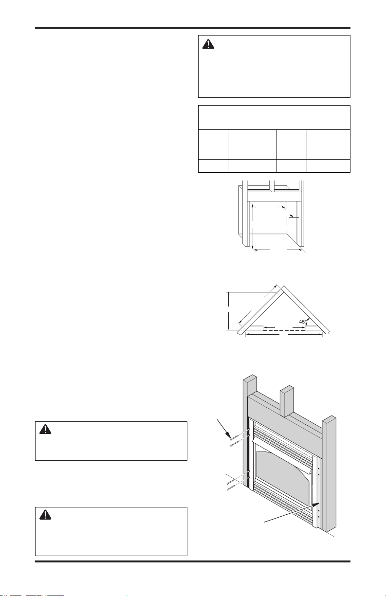
INSTALLATION
Depth
(Minimum)
Widt
h
(Inside to Inside)
Height
37"
411/2"
5
2
11
/
3
2
"
74"
TOP
VIEW
FOR 36"
MODELS
Continued
1. Frame in rough opening. The firebox framing
should be constructed of 2 x 4 lumber or heavier.
Use dimensions in Table 1 and rough opening
layout in Figure 8. Adjust framing so that firebox
flushes with finished wall surface. If installing
in a corner, use dimensions in Figures 8 and 9
for rough opening.
2.
Install gas piping to firebox location. See Installing
Gas Piping to Fireplace Location on page 13 and
Connecting Fireplace to Gas Supply, page 15.
IMPORTANT: If installing blower accessory
(circulating models with louvers only), see Hard-
Wiring Firebox
3. Carefully set firebox in front of rough open
ing with back of firebox inside wall opening.
IMPORTANT: If installing a perimeter trim
kit, see instructions included with trim acces
sory. You must install shoulder screws from
trim kit now.
4. Carefully insert firebox into rough opening.
5. Attach firebox to wall studs using nails or
wood screws through holes in nailing flange
(see Figure 10).
6. If using an optional perimeter trim kit, install
the trim after final finishing and/or painting
of wall. See instructions included with trim
accessory for attaching trim.
7. Install and properly test gas log heater. Fol
low installation instructions included with
the vent-free gas log heater that is being
installed.
IMPORTANT: When finishing your firebox,
combustible materials such as wall board, gypsum
board, sheet rock, drywall, plywood, etc. may be
butted up next to the sides and top of the firebox.
Combustible materials should never overlap the
firebox front facing.
, page 18.
WARNING: Use only noncombustible mortar or adhesives
when overlapping the front facing with noncombustible facing
material.
Rough Opening Dimensions for
Built-in Installation
Front Width
(Inside to Depth
Model Inside) Height (Minimum)
36" 41
-
-
Figure 8 - Rough Opening for Installing
-
Figure 9 - Rough Opening for Installing
Nails or
Wood
Screws
1
/2" 40 1/2" 20 3/4"
in Wall
in Corner Wall
WARNING: Do not allow any
combustible materials to overlap
the firebox front facing.
IMPORTANT: Noncombustible materials such as
brick, tile, etc. may overlap the front facing, but
should never cover any necessary openings like
louvered slots.
WARNING: Do not allow noncombustible materials to cover
any necessary openings like
louvered slots.
12
Figure 10 - Attaching Firebox to Wall
www.desatech.com
Nailing
Flange
Studs
113192-01B
Loading...