


 Loading...
Desa VCD36RNE, VCD36TPE, VCD36RPE, VCD36TP, VCD36TNE User Manual
...DIRECT-VENT FIREPLACE
OWNER’S OPERATION AND INSTALLATION MANUAL
|
|
|
|
|
|
|
|
|
|
|
|
|
|
|
|
|
|
|
|
|
|
|
|
|
|
|
|
|
|
|
|
|
|
|
|
|
|
|
|
|
|
|
|
|
|
|
|
|
|
|
|
|
|
|
|
|
|
|
|
|
|
|
|
|
|
|
|
|
|
|
|
|
|
|
|
|
|
|
|
|
|
|
|
|
|
|
|
|
|
|
|
|
|
|
|
|
|
|
|
|
|
|
|
|
|
|
|
|
|
|
|
|
|
|
|
|
|
|
|
|
|
|
|
|
|
|
|
NATURAL GAS Models |
|
|
|
|
|
NATURAL GAS Models |
|||||||||
(V)CD36RN, (V)CD36RNE |
|
|
|
|
|
(V)CD36TN, (V)CD36TNE, |
|||||||||
PROPANE/LP GAS ModelS |
|
|
|
|
|
PROPANE/LP GAS Models |
|||||||||
(V)CD36RP, (V)CD36RPE |
|
|
|
|
|
(V)CD36TP, (V)CD36TPE |
|||||||||
WARNING: If the information in this manual is not followed exactly, a fire or explosion may result causing property damage, personal injury or loss of life.
—Do not store or use gasoline or other flammable vapors and liquids in the vicinity of this or any other appliance.
—WHAT TO DO IF YOU SMELL GAS
•Do not try to light any appliance.
•Do not touch any electrical switch; do not use any phone in your building.
•Immediatelycallyourgassupplierfromaneighbor’s phone. Follow the gas supplier’s instructions.
•If you cannot reach your gas supplier, call the fire department.
—Installationandservicemustbeperformedbyaqualified installer, service agency or the gas supplier.
Save this manual for future reference.
For more information, visit www.desatech.com
WARNING: Improper installation, adjustment, alteration, service or maintenance can cause injury or propertydamage.Refertothismanualforcorrectinstallation and operational procedures. For assistance or additional information consult a qualified installer, service agency or the gas supplier.
This appliance may be installed in an aftermarket,* permanently located, manufactured (mobile) home, where not prohibited by local codes.
This appliance is only for use with the type of gas indicatedontheratingplate.Thisapplianceisnotconvertible for use with other gases, unless a certified kit is used.
* Aftermarket: Completion of sale, not for purpose of resale, from the manufacturer
State of Massachusetts: The installation must be made byalicensedplumberorgasfitterintheCommonwealth of Massachusetts.
Table of Contents
Safety Information................................................ |
3 |
Cleaning and Maintenance. |
............................... |
37 |
Product Identification............................................ |
4 |
Troubleshooting................................................. |
|
38 |
Local Codes......................................................... |
5 |
Replacement Parts............................................. |
|
44 |
Product Features.................................................. |
5 |
Service Hints...................................................... |
|
44 |
Pre-Installation Preparation.................................. |
5 |
Technical Service............................................... |
|
44 |
Location of Termination Cap................................ |
9 |
Specifications..................................................... |
|
44 |
Venting Installation Instructions.......................... |
10 |
Accessories........................................................ |
|
45 |
Fireplace Installation.......................................... |
21 |
Illustrated Parts Breakdown ........and Parts List |
46 |
|
Operating Fireplace............................................ |
31 |
Warranty Information............................ |
Back Cover |
|
Inspecting Burners............................................. |
36 |
|
|
|
|
www.desatech.com |
116035-01E |
Safety Information
 WARNING:Thisproductcontainsand/orgenerateschemicals known to the State of California to cause cancer or birth defects or other reproductive harm.
IMPORTANT: Read this owner’s manual carefully and completely beforetryingtoassemble,operate orservicethisfireplace.Improper use of this fireplace can cause serious injury or death from burns, fire, explosion, electrical shock and carbon monoxide poisoning.
 DANGER:Carbonmonoxide poisoning may lead to death!
Thisfireplacemustbeinstalledbyaqualified(cer- tified or licensed) service person. It has a sealed gas combustion chamber that uses a coaxial pipe (pipe within a pipe and having the same center) venting system. It brings in fresh air for combus- tion through the outer pipe and combustion gases are exhausted through the inner pipe. If the glass door assembly and venting pipe are not properly seated, connected and sealed, carbon monoxide leakage (spillage) can occur.
Carbon Monoxide Poisoning: Early signs of carbon monoxide poisoning resemble the flu, with headaches, dizziness or nausea. If you have these signs, the fireplace may not be working properly. Get fresh air at once! Have fireplace serviced. Somepeoplearemoreaffectedbycarbonmonoxide thanothers.Theseincludepregnantwomen,people withheartorlungdiseaseoranemia,thoseunderthe influence of alcohol and those at high altitudes.
Propane/LP & Natural Gas: Propane/LP and natural gas are odorless.An odor-making agent is added to the gas. The odor helps you detect a gas leak.However,theodoraddedtothegascanfade. Gas may be present even though no odor exists.
Makecertainyoureadandunderstandallwarnings. Keep this manual for reference. It is your guide to safe and proper operation of this fireplace.
 WARNING: Any change to thisfireplaceorit’scontrolscan be dangerous. Do not modify this fireplace under any circumstances. Any parts removed for servicingmustbereplacedprior to operating fireplace.
 WARNING:Donotuseablowerinsert,heatexchangerinsertor otheraccessorynotapprovedfor use with this fireplace.
 WARNING: This appliance is only for use with the type of gasindicatedontheratingplate. Thisapplianceisnotconvertible for use with other gases unless a certified kit is used.
 WARNING: Do not allow fans toblowdirectlyintothefireplace. Avoidanydraftsthatalterburner flame patterns.
Due to high temperatures, the appliance should be located out oftrafficandawayfromfurniture and draperies.
Do not place clothing or other flammable material on or near the appliance. Never place any objects on the appliance.
Donotusethisfireplacetocook foodorburnpaperorotherflammable material.
This fireplace reaches high temperatures. Keep children and adults away from hot surface to avoid burns or clothing ignition. Fireplacewillremainhotforatime after shutdown. Allow surface to cool before touching.
116035-01E |
www.desatech.com |
Safety information
Continued
Carefully supervise young children when they are in the room with fireplace.
Keep the area around your fireplace clear of combustible materials, gasoline and other flammable vapor or liquids. Do not run fireplace where these are used or stored.
1.For propane/LP fireplace, do not place pro- pane/LP supply tank(s) inside any structure. Locate propane/LP supply tank(s) outdoors. To prevent performance problems, do not use propane/LPfuel tank of less than 100 lbs. capacity.
2.If you smell gas
•shut off gas supply
•do not try to light any appliance
•donottouchanyelectricalswitch;donotuse any phone in your building
•immediately call your gas supplier from a neighbor’s phone. Follow the gas supplier's instructions
•ifyoucannotreachyougassupplier,callthe fire department.
3.Never install the fireplace
•in a recreational vehicle
•in windy or drafty areas where curtains or other combustible (flammable) objects can make contact with the fireplace front
•in high traffic areas
4.Turnfireplaceoffandletcoolbeforeservicing, installingorrepairing.Onlyaqualifiedservice person should install, service or repair this fireplace. Have fireplace inspected annually by a qualified service person.
5.You must keep control compartments, burn- ers and circulating air passages clean. More frequent cleaning may be needed due to ex- cessive lint and dust from carpeting, bedding material, etc. Turn off the gas valve and pilot light before cleaning fireplace.
6.Have venting system inspected annually by a qualifiedserviceperson.Ifneeded,havevent- ing system cleaned or repaired. See Cleaning and Maintenance, page 37.
7.Do not use any solid fuels (wood, coal, paper, cardboard, etc.) in this fireplace. Use only the gas type indicated on fireplace nameplate.
8.This appliance, when installed, must be elec- trically grounded in accordance with local codes or, in the absence of local codes, with the National Electrical Code, ANSI/NFPA 70 or the Canadian Electrical Code, CSA C22.1.
9.Do not use fireplace if any part has been ex- posed to or under water. Immediately call a qualifiedservicepersontoarrangeforreplace- ment of the unit.
10.Do not operate fireplace if any log is broken.
11.Do not operate fireplace with glass door removed, cracked or broken.
12.Provide adequate clearances around air openings.
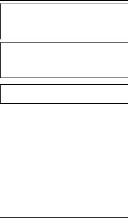
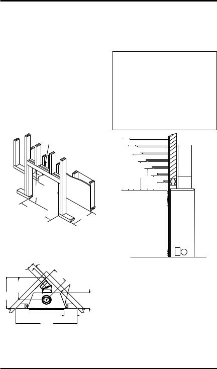
Product
Identification
Upper |
|
Rear Vent |
|
|
Flue Collar |
||
Louver |
|
|
|
Panel |
|
|
|
|
|
Top Vent |
|
|
|
Flue Collar |
|
|
|
Door |
|
|
|
Latch |
|
|
|
Nailing |
|
|
|
Flange |
|
Glass |
|
|
|
Door |
|
|
|
Assembly |
|
|
|
|
|
Log |
|
|
|
Set |
|
Junction |
|
Ember |
|
Box |
|
Tray |
|
Lower |
Control Valve |
Piezo Ignitor |
|
Louver |
|||
with Optional |
|||
Panel |
Variable Input |
||
|
Adjustment |
Remote |
|
|
and Blower |
||
|
|
||
|
|
Control Mount |
Figure 1 - Top and Rear Direct-Vent
Fireplaces
www.desatech.com |
116035-01E |

Local Codes
Installandusefireplacewithcare.Followalllocal codes. In the absence to local codes, use the cur- rent National Fuel Gas Code ANSI Z223.1/NFPA 54* (USA)orthecurrentCSA-B149.1 Installation Code (Canada).
*Available from:
American National Standards Institute, Inc.
1430 Broadway
New York, NY 10018
National Fire Protection Association, Inc.
Batterymarch Park
Quincy, MA 02269
Product Features
Theseareafewfactsthatcanhelp youunderstand and enjoy your direct-vent fireplace:
•The CD36R dedicated rear vent is best suited for flush or corner installations when vented horizontally through an exterior wall.
•The CD36T dedicated top vent is suited for any application where height is necessary to terminate the venting system either through the roof (vertical) or to gain sufficient height and offset to vent to an outside/exterior wall (horizontal).
•The vent pipe installation is very important to allow for proper operation. You must select the appropriate unit for your application and follow the venting instructions to plan your installation.
•This fireplace may be installed in any room of your house provided all local codes and these installation instructions are followed.
•Models (V)CD36R/T are equipped with a mil- livolt gas control system that does not require electricitytooperate.Apiezoignitorisprovidedto light the pilot without using matches or lighters.
•Models (V)CD36RE/TE are equipped with an electronicignitionsystemthatrequires120VAC to operate. An electrode ignitor automati- cally lights the pilot flame when the fireplace is turned on.
•All models can accept an optional circulating air blower when 120 VAC connection is sup- plied. If you plan to install an optional blower, do not forget to wire the fireplace outlet when framing.
•Each time you turn on your fireplace, you may notice some amount of condensation on the in- sideofthefireplaceglass.Thisisnormalandwill disappear after 10-20 minutes of operation.
•Yourdirect-ventgasfireplacesystem(fireplace and venting) is a balanced and sealed gas oper- ating unit. It is highly efficient because it uses outsideairforcombustionwhileindependently heating the indoor air.
Pre-Installation
Preparation
Location and space
requirements
Determine the safest and most efficient location for your DESA direct-vent fireplace. Make sure that rafters and wall studs are not in the way of the venting system. Choose a location where the heat output is not affected by drafts, air conditioning ducts, windows or doors. Figure 2 shows some commonlocations.Beawareofallrestrictionsand precautions before deciding the exact location for your fireplace and termination cap.
When deciding the location of your fireplace, follow these rules:
•Donotconnectthisfireplaceventingtoachim- ney flue serving a separate solid-fuel burning fireplace or appliance.
•Due to high temperatures, do not locate this fireplace in high traffic areas, windy or drafty areas or near furniture or draperies.
•Proper clearances must be maintained.
•If your fireplace is to be installed directly on carpeting,vinyltileoranycombustiblematerial other than wood, it must be installed on a metal orwoodpanelextendingthefullwidthanddepth of the fireplace. See Figure 3, page 6.
•Yourfireplaceisdesignedtobeusedinzeroclear- anceinstallations.Wallorframingmaterialcanbe placeddirectlyagainstanyexteriorsurfaceonthe back, sides or top of your fireplace, except where standoffspacersareintegrallyattached.Ifstandoff spacers are attached to your fireplace, these spac- ers can be placed directly against wall or framing material. See framing details on page 7.
Flush with |
Corner |
a wall |
installation |
Through exterior wall enclosed in a chase
Figure 2 - Common Fireplace Locations
116035-01E |
www.desatech.com |
Pre-Installation
Preparation
Continued
•If you plan on installing a television or enter- tainmentcenterrecessedaboveyourfireplace,it is recommended that you maintain a minimum 18" above top of louver opening.
•When locating termination cap, it is important to observe the minimum clearances shown in Figure 7, page 8.
•If recessing into a wall, you can avoid extra framing by positioning your fireplace against an already existing framing member.
•Do not recess termination cap into a wall or siding.
•You may paint the termination cap with 450ºF (232ºC) heat-resistant paint to coordinate with the exterior finish.
•There must not be any obstruction such as bushes, garden sheds, fences, decks or util- ity buildings within 24" from the front of the termination cap.
•Do not locate termination cap where excessive snow or ice build up may occur. Be sure to clear vent termination area after snow falls to prevent accidental blockage of venting system. When using snow blowers, do not direct snow towards vent termination area.
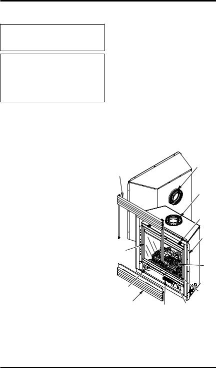
25" (635 mm)
15" (381 mm)
36" (914 mm)
Figure 3 - Fireplace Bottom Dimensions
Packaging and Removal
The (V)CD36R/T direct vent gas fireplace heater is packaged with:
-one box containing a 4-log set located on the burner in the firebox.
-one bag containing the owner’s manual with installation instructions, operator’s guide, and warranty information.
-one bag of glowing ember material.
-one bag of vermiculite hearth treatments.
Remove the shrink-wrap securing the 2 carton trays to the unit. Lift the top carton tray off and remove the four corner posts. Discard the bottom tray once the unit is moved into position.
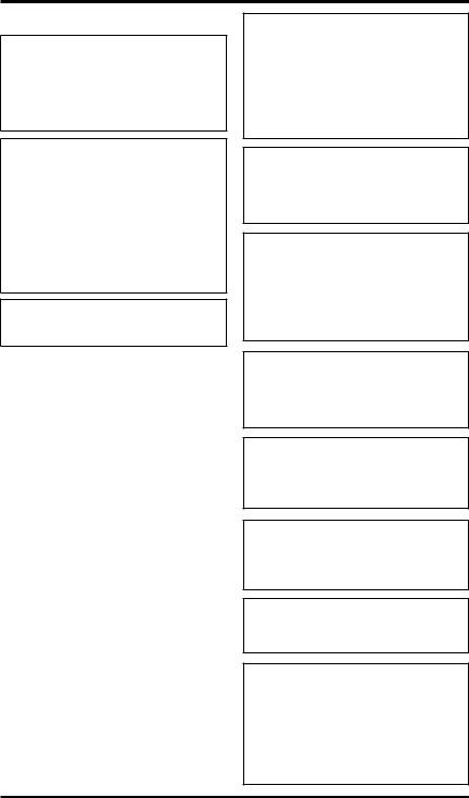
Note: On rear vent models you must remove the fiberboard collar protector located on the rear collar before installing the fireplace and venting system. See Figure 4.
Fireboard Collar Protector
Figure 4 - Removing Collar Protector
(Rear Vent Fireplace)
Clearances
Minimum clearances to combustibles for the fire- |
||
place are as follows: |
|
|
*Back and sides |
0"/mm |
|
Perpendicular walls |
12" |
(305 mm) |
Floor |
0"/mm |
|
Ceiling to louver opening 40" |
(1016 mm) |
|
Front |
36" |
(914 mm) |
Top of Standoffs |
0"/mm |
|
Vent Surfaces |
1"(26mm)(Seeventing |
|
|
instructionsforspecific |
|
Mantel Clearances |
vent clearances.) |
|
(SeeMantelClearances |
||
|
for specifics on mantel |
|
|
clearances.) |
|
Combustible material with a maximum thick- ness of 5/8" may be flush with the top front of fireplace.
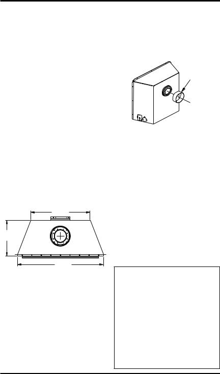
NOTICE: This fireplace is intended for use as supplemental heat.Usethisfireplacealongwith yourprimaryheatingsystem.Do not install this fireplace as your primaryheatsource.Ifyouhavea centralheatingsystem,youmay run system’s circulating blower while using fireplace. This will help circulate the heat throughout the house. In the event of a power outage, you can use this fireplace as a heat source.
www.desatech.com |
116035-01E |
Pre-Installation
Preparation
Continued
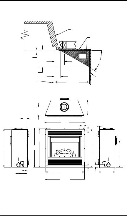
framing and finishing
Figure 5 shows typical framing of this fireplace. Figure 6 shows framing for corner installation. All minimum clearances must be met.
For overall unit dimensions, framing allowances and vent collar locations, see Unit Dimensions, Figure 9, page 8.
For available accessories for this fireplace, see Accessories onpage45.Ifyouareusingaseparate combustible mantel piece, refer to Figure 7 and Figure 8, page 8 for proper height and clearances. You can install noncombustible mantels at any height above the fireplace.
Note: Noncombustible mantels may discolor!
24" Vertical
Double Stud
36" |
|
(914 mm) |
|
36 1/4" |
|
(921 mm) |
14 3/4" |
|
|
|
(375 mm) |
Figure 5 - Framing Clearances for Installation Against an Exterior Wall
6 5/8" ( 168 mm) TO CENTER
OF REAR VENT
21" (533 mm) TO CENTER OF TOP VENT
28 5/8"
(727 mm)
2 1/2" (63 mm) |
THESE DIMENSIONS ALLOW |
|
MIN. 1" (26 mm) |
FOR 1" OF CLEARANCE |
|
|
AT THE SIDES AND BACK |
|
14 3/4" |
OF THE FIREPLACE |
|
HOWEVER, 0" CLEARANCE |
||
(375 mm) |
||
IS ALSO PERMITTED AT |
||
|
ALL SIDES WHEN FRAMED |
|
|
14 3/4" |
|
|
(375 mm) |
|
|
TO NAILING |
|
|
FLANGES |
|
|
12 1/4" |
|
|
(311 mm) |
|
|
TO |
56 |
3/4" |
OPENING |
|
(1441 mm)
Figure 6 - Framing Clearances for Corner Installation
MANTEL CLEARANCES
Figure 7 shows projected mantel depths at various heightsabovethetopofthelouveropening.Figure 8, page 8, shows the minimum allowable distances from various mantel components in relation to the both sides of the fireplace opening.
 WARNING: When finishing appliance, do not overlap combustible materials onto the black frontface.Brick,tile,orothernoncombustible materials may be applied to the face provided that any fireplace openings are not blocked and gaps in the material used and the face are sealed with a non-combustible caulking.
|
|
|
|
|
|
|
|
|
|
|
1 |
|
|
|
|
|
|
|
|
|
|
|
|
2 |
|
|
|
|
|
|
|
|
|
|
|
|
3 |
|
A |
|
|
|
|
|
|
|
|
||||
|
|
|
|
|
|
|
|
4 |
||||
|
||||||||||||
|
|
|
|
|
|
|
|
|
|
|
||
|
|
B |
|
|
|
|
|
|
|
5 |
||
|
|
|
|
|
|
|
|
|
|
|
|
|
|
|
|
C |
|
|
|
|
6 |
||||
|
|
|
|
|
|
|
|
|
|
|
|
|
|
|
|
|
|
|
D E |
|
|
7 |
|||
|
|
|
|
|
|
|
||||||
|
|
|
|
|
|
|
|
|
|
|
|
|
|
|
|
|
|
|
|
|
F |
|
|
||
|
|
|
|
|
|
|
|
G |
||||
|
|
|
|
|
|
|
|
|
|
|
||
|
|
|
|
Mantel from |
|
|
|
|
|
Top of Louver |
|
Ref. |
Mantel Depth |
Ref. |
Opening |
||
|
|
|
|
|
|
1 |
16" |
(406 mm) |
A |
14" |
(356 mm) |
|
|
|
|
|
|
2 |
14" |
(356 mm) |
A |
12" |
(305 mm) |
|
|
|
|
|
|
3 |
12" |
(305 mm) |
B |
10" |
(254 mm) |
|
|
|
|
|
|
4 |
10" |
(254 mm) |
C |
8" (203 mm) |
|
|
|
|
|
||
5 |
8" (203 mm) |
D |
6" (152 mm) |
||
|
|
|
|
||
6 |
4" (101 mm) |
F |
4" (101 mm) |
||
|
|
|
|
|
|
7 |
2" |
(51 mm) |
G |
2" |
(51 mm) |
|
|
|
|
|
|
Figure 7 - Clearances for Combustible Mantels
116035-01E |
www.desatech.com |
Pre-Installation Preparation
Continued
|
|
Outer Surround |
|
|
|
|
Combustible |
|
|
|
Material May |
|
|
|
Be Used |
1 1/2" |
|
SAFE |
|
(38 mm) |
|
ZONE |
|
6" |
|
|
|
|
|
33° |
|
(152 mm) |
|
||
|
|
||
5 1/2" |
|
|
|
(140 mm) |
3 3/4" |
|
|
|
|
|
|
|
(95 mm) |
|
Perpendicular |
To Fireplace |
|
12" |
|
|
Side Wall |
||
Opening |
|
(305 mm) |
|
Figure 8 - Side Clearances for Combustible Materials
7 5/8" (194 mm) TO CENTER OF 8" TOP VENT
14 3/4"
(375 mm) TO NAILING FLANGES
4" (102 mm)
TO
NAILING FLANGE
36 1/4"
(921 mm) TO NAILING FLANGE
35 3/4" |
36 3/4" |
(908 mm) |
(934 mm) |
|
WALL SWITCH |
|
WIREWAY |
8" (203 mm) |
4 1/2" (114 mm) |
|
ELECTRICAL |
||
GAS SUPPLY |
||
INLET |
||
INLET |
||
|
38" |
|
|
(965 mm) |
|
|
2" |
5/8" |
|
(51 mm) |
(16 mm) |
|
|
2" |
|
|
(51 mm) |
|
|
36" |
|
|
(914 mm) |
|
|
FACE DIM. |
|
|
|
25" (635 mm) |
|
WALL SWITCH |
TO CENTER OF |
|
WIREWAY |
8" REAR VENT |
|
2 " |
|
|
(51 mm) |
|
36 1/4" |
|
|
|
|
|
15 3/8" |
|
(921 mm) |
|
|
|
|
(390 mm) |
||
FACE DIM. |
2 1/2 " |
|
|||||
|
|
|
(63 1/2 mm) |
|
|
|
|
37" (940 mm) TO NAILING FLANGE
Figure 9 - Rear/Top Common Dimensions
www.desatech.com |
116035-01E |
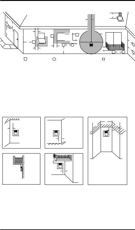
Location of Termination Cap
D
E
V
B L
|
|
|
|
|
|
H |
|
C |
|
|
|
|
|
|
Fixed |
|
|
B |
V |
I |
|
Closed |
V |
Openable |
Fixed |
|
|
|
Openable |
|
|
Closed |
|
|
F |
|
|
|
B |
|
|
V |
|
|
|
|
|
B |
V J |
X |
G |
|
|
|
|
|
B |
|
A |
|
M |
|
|
|
N  N
N 
|
G |
|
V |
|
G |
V K X |
V |
|
|
|
|
|
A |
||
V TERMINATION CAP |
X AIR SUPPLY INLET |
G |
GAS METER |
|
RESTRICTED AREA |
|
|
|
|||||||
|
|
|
|
|
(TERMINATION PROHIBITED) |
||
A= clearance above grade, veranda, porch, deck, or balcony [*12 inches (30.5mc) minimum]
B= clearance to window or door that may be opened
[12 inches (30.5cm) minimum]
C = clearance to permanently closed window [minimum 12 inches (30.5cm) recommended to prevent condensation on window]
D = vertical clearance to ventilated soffit located above the terminal within a horizontal distance of 24 inches (61cm) from the center-line of the terminal [18 inches (45.7cm) minimum]
E= clearance to unventilated soffit [12 inches (30.5cm) minimum]
F= clearance to outside corner (see below)
G= clearance to inside corner (see below)
H= *not to be installed above a meter/regulator assembly within
36 inches (91.4cm) horizontally from the center-line of the regulator
I= clearance to service regulator vent outlet [*72 inches (182.9cm) minimum]
J= clearance to non-mechanical air supply inlet to building or the combustion air inlet to any other fireplace [*12 inches (30.5cm) minimum]
K= clearance to a mechanical air supply inlet [*72 inches (182.9cm) minimum]
L= † clearance above paved side-walk or a paved driveway located on public property [*84 inches (213.3cm) minimum]
M= clearance under veranda, porch, deck [*12 inches (30.5cm) minimum ‡]
N= clearance above a roof shall extend a minimum of 24 inches (61cm) above the highest point when it passes through the roof surface and any other obstruction within a horizontal distance of 18 inches (45.7cm)
† vent shall not terminate directly above a side-walk or paved driveway which is located between two single family dwellings and serves both dwellings*
‡ only permitted if veranda, porch, deck or balconey is fully open on a minimum of 2 sides beneath the floor* * as specified in CAN/CSA B149 (.1 or .2) Installation Codes (1991) for Canada and U.S.A.
Note: Local codes or regulations may require different clearances
Termination Clearances for Buildings with Combustible and Noncombustible Exteriors
Inside Corner |
Outside Corner |
Recessed Location |
|
|
|
D |
|
|
|
C |
C |
A |
A = 6" (15.2cm) |
|
E |
|
|
|
|
V |
V |
V |
|
|
B |
B = 6" (15.2cm) |
|
Balcony with No Side Wall |
Balcony with Perpendicular Side Wall |
|
H |
|
G |
V |
|
|
||
V |
J |
|
|
||
|
Combustible & |
|
|
Noncombustible |
|
G = 12" (30.5cm) minimum clearance |
H = 24" (61cm) |
|
J = 20" (50.8cm) |
||
|
C = Maximum depth of 48" (121.9cm) for recessed location
D = Minimum width for back wall of recessed location - Combustible - 38" (965mm) Noncombustible - 24" (61cm)
E = Clearance from corner in recessed locationCombustible - 6" (15.2cm) Noncombustible - 2" (5.1cm)
Figure 10 - Minimum Clearances for Termination Cap
116035-01E |
www.desatech.com |
Venting Installation
Instructions
NOTICE: Read these instructions completely before attempting installation.
These models are tested and approved for use with DESA (direct-vent) pipe components and terminations.
Theventingsystemmustterminateontheoutsideof the structure and can not be attached to a chimney or flue system serving a separate solid fuel or gas burning appliance. A direct-vent appliance must have its own venting system. DO NOT common vent this appliance.
These models are approved to be vented either horizontally through an outside wall or vertically through a roof or chase enclosure using the fol- lowing:
•When venting system terminates horizontally on an outside wall, you may install a standoff if the termination cap is to be installed directly on a combustible finish such as vinyl, wood, stucco, etc.
•Never run the vent downward as this may cause excessive temperatures which could cause a fire.
•Vent pipe air space clearances to combustibles are 1" on all sides except on the horizontal sections, which requires 2" clearance from the top of the pipe. Where the termination cap penetrates a combustible wall, 1" air space clearance is required.
•Havefireplaceandselectedventcomponentson handtohelpdeterminetheexactmeasurements when elbowing or offsetting. Always use wall firestops when penetrating walls and firestops when penetrating ceilings or attic spaces.
•Install horizontal venting with a 1/4" rise for every 12" of run toward the termination.
 WARNING: Read all instructionscompletelyandthoroughly before attempting installation.
Failure to do so could result in seriousinjury,propertydamage or loss of life.
IMPORTANT: Do not seal vent cap to pipe. Cap must be removable for servicing.
NOTICE:Failuretofollowtheseinstructions will void the warranty.
NOTICE:Donotsealtermination cap to vent pipe. Cap must be removable for vent inspection and maintenance.
Installation Precautions
•Wear gloves and safety glasses for protection
•Use extreme caution when using ladders or when on roof tops
•Be aware of electrical wiring locations in walls and ceilings
The following actions will void the warranty on your venting system:
•Installation of any damaged venting component
•Unauthorizedmodificationoftheventingsys- tem (Do not cut or alter vent components)
•Installation of any component part not manufactured or approved by DESA
•Installation other than as instructed by these instructions
 WARNING: This gas fireplace andventassemblymustbevented directlytotheoutside.Theventing system must NEVER be attached to a chimney serving a separate solidfuelburningappliance.Each direct-vent gas appliance must useaseparateventsystem.Donot use common vent systems.
 WARNING: Vent pipe air spaceclearancestocombustibles are 1" on all sides except on the horizontalsections,whichrequire 2" clearances from the top of the pipe. Where the termination cap penetratesacombustiblewall,1" air space clearance is required.
10 |
www.desatech.com |
116035-01E |
Venting Installation instructions
Continued
INSTALLATION PLANNING
There are two basic types of direct-vent in- stallation:
•Horizontal Termination
•Vertical Termination
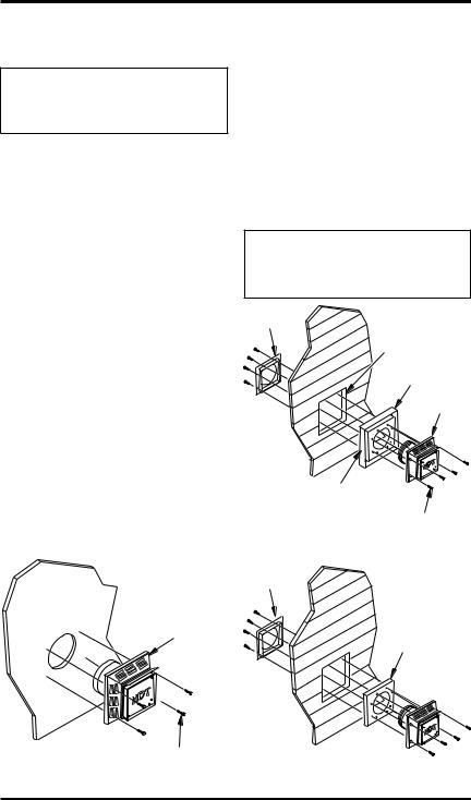
Horizontal Termination Installation
IMPORTANT: Horizontal square terminations require only inner portion of wall firestop. Hori- zontalinstallationsusingroundterminationrequire exterior portion of wall firestop (see Figure 20, page 14).
1.Setthefireplaceinitsdesiredlocationanddeter- minetherouteyourhorizontalventingwilltake. Do not secure the fireplace until all venting has beeninstalled.Someinstallationsrequiresliding thefireplaceinandoutofpositiontomakefinal venting connections. Figures 18 through 25 on pages 13 through 16 show different configura- tionsforventingwithhorizontalterminationthat willhelpyoudecidewhichapplicationbestsuits your installation. Check to see if wall studs or roof rafters are in the path of your desired vent- ingroute.Iftheyare,youmaywanttoadjustthe location of the fireplace.
2.Direct vent pipe sections and components are designed with special twist-lock connections.
Twist-Lock Procedure: The female ends of the pipes have locking lugs (indentations). These lugs will slide straight into matching slots on the male ends of adjacent pipes. Push pipe sec- tions together and twist one section clockwise approximatelyone-quarterturnuntilthesections arefullylocked(seeFigure11).Note: Horizon- tal runs of vent must be supported every three feet. Use wall straps for this purpose.
3.Any straight pipe section, a 45° or 90° elbow can be used when first connecting the venting system to the fireplace. Elbows are designed to twist-lock into any of four 90° positions to direct the venting system to the desired loca- tion. IMPORTANT: Do not attempt to alter the configuration of the elbow by cutting, twisting, bending, etc.
4.Assemblethedesiredcombinationofpipeand elbows to the fireplace flue collar. If there are long portions of venting run, pre-assembled pipe sections may be installed as subassem- blies for convenience.
5.Carefullydeterminethelocationwherethevent pipe assembly will penetrate the outside wall. The center of the hole should line up with the center-lineofthehorizontalventpipe.Markthe wall for a 10 3/4" x 10 3/4" square hole. Cut and framethesquareholeintheexteriorwallwhere the vent will be terminated. If the wall being penetrated is constructed of noncombustible material, such as masonry block or concrete, a 8 1/2" hole with zero clearance is acceptable (see Figure 12).
Female |
Male |
|
Slots |
||
Locking Lugs |
||
|
Figure 11 - Vent Pipe Connections
Vent Opening
Combustible Wall  10 3/4" Inside Framing
10 3/4" (273 mm)
(273 mm)
10 3/4"
(273 mm)
(Framing
Vent Opening Detail)
Noncombustible Wall
8 1/2" |
(216 mm) |
Center of |
Hole |
Figure 12 - Vent Opening Requirements
116035-01E |
www.desatech.com |
11 |
Venting Installation
instructions
Continued
 WARNING: Do not recess vent termination into any wall. This will cause a fire hazard.
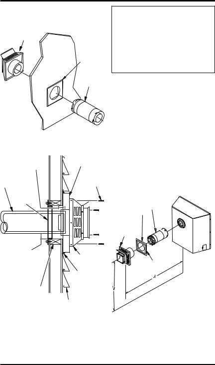
6.Noncombustible Exterior Wall: Position the horizontal vent cap in the center of the 8 1/2" roundholeandattachtotheexteriorwallwith four wood screws provided. Before attaching the vent cap to exterior wall, run a bead of non-hardeningmastic(pliablesealant)around theoutsideedgestomakeasealbetweenitand theoutsidewall.Note: Thefourwoodscrews provided should be replaced with appropriate fasteners for stucco, brick, concrete or other types of sidings (see Figure 13).
Combustible Exterior Wall: For vinyl siding, stucco or wood exteriors, a siding standoff may be installed between the vent cap and exterior wall. The siding standoff prevents excessive heat from damaging the siding materials. Siding material must be cut to accommodate standoff. Bolt the vent cap to the standoff. Apply non-hardening mastic around outside edge of standoff. Position the standoff/cap assembly in the center of the 10 /4" square hole and attach to exterior wall with wood screws provided (see Figure 14). The siding standoff must sit flush against the exterior fascia material.3
7.Combustible Exterior Wall Only: Fittheouter and inner wall firestop into the wall before connecting horizontal run to vent cap (see Figure 15).
Vent Cap
Wood Screw
Figure 13 - Installing Horizontal Vent Cap
(Noncombustible Exterior)
8.Carefully move fireplace, with vent assembly attached, toward wall and insert vent pipe into horizontal termination. The pipe overlap should be a minimum of 11/4".
9.Combustible Exterior Wall Only: Slide wall firestopagainstinteriorwallsurfaceandattach with screws provided (see Figure 16, page 13). See Figure 17, page 13, for horizontal termination details.
10.Place fireplace into position and shim with noncombustible material, if needed. Nail or screw side flanges to framing to secure unit in place. IMPORTANT: Make sure fireplace is level before securing. If fireplace is not level it will not work properly.
NOTICE:Donotsealtermination cap to vent pipe. Cap must be removable for vent inspection and maintenance.
Inner Wall
Firestop
Cut Siding Away to Fit Standoff
Standoff
Vent
Cap
Apply Mastic to All Four Sides
Screws
Figure 14 - Installing Siding Standoff
(Combustible Exterior Wall)
Inner Wall
Firestop
Inner Wall
Firestop
Figure 15 - Installing Outer Wall Firestop
(Combustible Exterior Wall)
12 |
www.desatech.com |
116035-01E |
Venting Installation
instructions
Continued
Vent
Cap
Inner Wall
Firestop
Pipe
Section
Figure 16 - Installing Inner Wall Firestop
Minimum Pipe |
Siding Standoff |
|
Overlap 11/4" |
||
|
||
Direct-Vent |
|
|
Pipe |
Screws |
|
|
Wall |
|
|
|
|
|
|
|
Firestop |
|
|
|
||
Maintain 1" |
|
|
|
|
|||
Minimum Air |
|
|
|
|
|||
Space Around |
|
|
High Wind |
||||
Outer Pipe When |
Termination |
||||||
Penetrating a Wall |
Apply |
||||||
|
|
|
|
|
|
||
|
|
|
|
|
|
Mastic to |
|
10 |
3 |
4 |
3 |
4 |
" |
Outside |
|
|
/ " x 10 |
|
/ |
Edge of |
|||
Framed Opening |
|||||||
Standoff |
|||||||
|
|
|
|
|
|
||
|
|
Exterior Wall with Vinyl Siding |
|||||
Figure 17 - Typical Horizontal Termination Cap Mounting with Additional Siding Standoff Installed
 WARNING: Never run vent downward as this may cause excessive temperatures which could cause a fire. Operation of improperly installed and maintained venting system could resultinseriousinjury,property damage or loss of life.
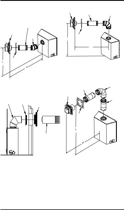
Horizontal Termination Configurations
Figures 18 through 25 show different configura- tions and alternatives for venting with horizontal termination. Each figure includes a chart with criticalminimumandmaximumdimensionswhich MUST be met. IMPORTANT: Remember that a horizontal run of venting must have a 1/4" rise for every 12" of run toward the termination.
GROUND FLOOR INSTALLATION REAR VENT
Recommended Applications fo Rear Vent Model (V)CD36R:
•Installation using cabinet surrounds
•Through the wall using round or square termi- nation (up to a maximum of 18” of horizontal pipe)
•Corner installation (Using one 45° elbow and a maximum of 18" of horizontal pipe).
Straight/Adjustable
Pipe 18" Max.
Horizontal
Square
Termination 
H |
|
TO |
Wall Firestop |
|
Square Termination
Vertical (V) |
Horizontal (H) |
25 1/2" Min. |
22" Max |
Figure 18 - Horizontal Termination
Configureation for Flush Installation
(Model (V)CD36R)
116035-01E |
www.desatech.com |
13 |
Venting Installation |
Horizontal |
Straight/ |
|
|||||||
|
instructions |
Square |
|
Adjustable |
90° |
|||||
|
Termination |
|||||||||
|
|
|
|
|
|
|
|
|
|
|
|
|
|
Continued |
|
|
|
|
Pipe 24" Max. |
Elbow |
|
|
|
|
|
|
|
|
|
|||
|
|
Straight/Adjustable |
|
|
|
|
|
|||
|
|
Pipe 18" Max. |
|
|
|
|
|
|
||
Horizontal Square |
|
|
|
|
|
|
|
|||
Termination |
|
|
45° |
|
|
|
Wall |
|
|
|
|
|
|
|
Elbow |
|
|
|
|
|
|
|
|
|
|
|
V |
|
Firestop |
|
||
|
|
|
|
|
|
|
|
|||
|
|
|
|
|
|
|
|
|
H |
|
|
Wall |
|
|
|
|
|
|
Corner Installation |
|
|
|
Firestop |
|
|
|
|
|
|
|||
|
|
|
|
|
Vertical (V) |
Horizontal (H) |
|
|||
|
|
|
|
|
|
|
|
|||
|
|
|
|
Corner Installation |
|
45 1/2" Min. |
32 1/2" Max |
|
||
|
|
|
|
|
Figure 21 - Horizontal Termination |
|||||
|
|
|
Vertical (V) |
Horizontal (H) |
|
|||||
|
|
|
25 1/2" Min. |
24" Max |
Configuration For Corner Installation |
|||||
Figure 19 - Horizontal Termination |
Using One 90° Elbow (Model (V)CD36T) |
|||||||||
|
|
Not to Exceed |
|
|||||||
Configuration for Corner Installation |
|
|
90° Elbow |
|||||||
|
|
(H) Limits |
||||||||
|
|
(Model (V)CD36R) |
Square |
|
||||||
|
|
|
|
|
||||||
|
|
|
|
|
|
|
|
As |
||
|
|
|
|
Exterior |
Termination |
|
||||
90° |
Wall |
|
Portion of Wall |
|
|
|
|
Required |
||
|
|
|
|
|
for (V), |
|||||
Elbow |
|
Firestop (Round |
|
|
|
|
||||
Firestop |
|
|
|
|
||||||
|
|
|
|
See Chart |
||||||
|
Termination Only) |
|
|
|
|
|||||
|
|
|
|
|
|
|
|
|||
|
|
|
|
|
|
|
|
for Pipe |
||
|
|
|
|
|
|
|
|
|
|
|
|
|
|
|
|
|
TO |
|
|
|
Section |
|
|
|
|
|
|
H |
|
|
|
|
|
|
|
|
|
|
|
|
Wall |
|
Required |
|
|
|
|
|
|
|
|
|
|
|
|
|
|
|
|
|
|
|
Firestop |
|
|
|
|
|
|
|
Horizontal |
|
|
|
|
|
|
|
|
|
|
Round |
|
|
|
|
|
|
|
|
|
|
Termination |
|
|
|
|
|
Figure 20 - Horizontal Termination
Configuration Round Termination
(Model (V)CD36T)
GROUND FLOOR INSTALLATION
RecommendedApplications for Rear Vent Model (V)CD36T:
•Installation using cabinet surrounds
•Through the wall using round or square termination (up to 24" horizontal pipe)
•Corner installation (Using one 90° elbow and a maximum of 24" of horizontal pipe)
Required |
Vertical (V) |
Allowable |
Vertical (V) |
Vertical Pipe |
Horizontal (H) |
45 1/2" |
None |
26" Max. |
57 1/4" Min. |
1 ft. |
30" Max. |
69 1/4" Min. |
2 ft. |
74" Max. |
81 1/2" Min. |
3 ft. |
98" Max. |
94" Min. |
4 ft. |
122" Max. |
106" Min. |
5 ft. |
146" Max. |
159" Min. |
9 ft. |
20' Max. |
Figure 22 - Horizontal Termination
Configuration with Vertical Rise and One
90° Elbow (Model (V)CD36T)
14 |
www.desatech.com |
116035-01E |

Venting Installation instructions
Continued
SNORKEL TERMINATION INSTALLATION
Recommended Applications Models (V)CD36R and (V)CD36T:
•Installations requiring vertical rise on building exterior.
•Installationusingsnorkelterminationtoachieve 1 ft. above grade.
Snorkelterminationsareavailableforinstallations requiringaverticalriseontheexteriorofthebuild- ing. If installing snorkel below grade
youmustprovideproperdrainagetopreventwater fromenteringsnorkel(seeFigure23,page15).Do not back fill around snorkel termination.
Snorkel |
Termination |
12" |
Min. |
|
|
Snorkel |
Snorkel |
Wall |
Termination |
Termination |
|
|
Firestop |
|
|
|
|
|
|
90° Elbow |
|
|
|
12" Min. |
12" Min. |
|
|
Adequate |
|
|
Drainage |
|
|
Figure 23 - Snorkel Termination Configuration For Below Ground Installation
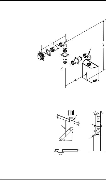
HORIZONTAL VENT INSTALLATIONS USING MULTIPLE 90° ELBOWS (V)CD36T TOP VENT
The following configurations show the minimum vertical rise requirements for a horizontal system using two 90° elbows.
90° Elbow
Venting with Two 90° Elbows
|
Horizontal (H)+ |
Vertical (V) |
Horizontal (H2) |
7' Min. |
10' Max |
8' Min. |
12' Max |
9' Min. |
14' Max |
10' Min. |
16' Max |
11' Min. |
18' Max |
13' Min. |
20' Max |
90° Elbow
Figure 24 - Horizontal Termination Configuration For Venting Using Two 90° Elbows
(Model (V)CD36T)
116035-01E |
www.desatech.com |
15 |
Venting Installation instructions
|
|
Continued |
|
Venting with Two 90° Elbows |
|
||
|
|
Horizontal (H)+ |
|
Vertical (V) |
Horizontal (H) |
Horizontal (H2) |
|
5' Min. |
2' Max. |
6' Max |
|
6' Min. |
3' Max. |
8' Max |
|
7' Min. |
4' Max. |
10' Max |
|
8' Min. |
5' Max. |
12' Max |
90° |
12' Min. |
8' Max. |
20' Max |
Elbow |
20' Min. |
8' Max. |
20' Max |
|
90° Elbow
HOT
90°  Elbow
Elbow
Figure 25 - Horizontal Termination Configuration for Venting Using Three 90° Elbows
(Model (V)CD36T)
installation for vertical
termination
Note: Vertical restrictor must be installed in all vertical installations.
1.Determine the route your vertical venting will take. If ceiling joists, roof rafters or other framing will obstruct the venting system, consideranoffset(seeFigure26)toavoidcut- tingloadbearingmembers.Note: Payspecial attention to these installation instructions for requiredclearances(airspace)tocombustibles when passing through ceilings, walls, roofs, enclosures, attic rafters, etc. Do not pack air spaces with insulation. Also note maximum vertical rise of the venting system and any maximum horizontal offset limitations.
2.Set the fireplace in desired location. Drop a plumb line down from the ceiling to the posi- tion of the fireplace exit flue. Mark the center pointwheretheventwillpenetratetheceiling. Drill a small locating hole at this point.
Drop a plumb line from the inside of the roof to the locating hole in the ceiling. Mark the center point where the vent will penetrate the roof. Drill a small locating hole at this point.
|
|
|
Horizontal |
|
Roof |
Frame Member |
|
|
|
||
|
Flashing |
|
|
Wall |
|
WS-58 |
|
|
Wall Strap |
||
Strap |
|
||
|
|
|
|
|
|
OSR58-30 |
|
|
|
30° Offset |
|
|
|
Return |
|
|
45° |
2 - 2 x 4 |
|
|
Vertical |
||
|
Elbows |
||
|
Header |
||
|
|
||
Figure 26 - 45° and 30° Offset with Wall Strap
16 |
www.desatech.com |
116035-01E |
Loading...