


 Loading...
DIRECT-VENT FIREPLACE
OWNER’S OPERATION AND INSTALLATION MANUAL
NATURAL GAS Models
(V)TC36N Series
PROPANE/LP GAS ModelS
(V)TC36P Series
WARNING: If the information in this manual is not followed exactly, a fire or explosion may result causing property damage, personal injury or loss of life.
—Do not store or use gasoline or other flammable vapors and liquids in the vicinity of this or any other appliance.
—WHAT TO DO IF YOU SMELL GAS
•Do not try to light any appliance.
•Do not touch any electrical switch; do not use any phone in your building.
•Immediatelycallyourgassupplierfromaneighbor’s phone. Follow the gas supplier’s instructions.
•If you cannot reach your gas supplier, call the fire department.
—Installationandservicemustbeperformedbyaqualified installer, service agency or the gas supplier.
Save this manual for future reference.
For more information, visit www.desatech.com
WARNING: Improper installation, adjustment, alteration, service or maintenance can cause injury or propertydamage.Refertothismanualforcorrectinstallation and operational procedures. For assistance or additional information consult a qualified installer, service agency or the gas supplier.
This appliance may be installed in an aftermarket,* permanently located, manufactured (mobile) home, where not prohibited by local codes.
This appliance is only for use with the type of gas indicatedontheratingplate.Thisapplianceisnotconvertible for use with other gases, unless a certified kit is used.
* Aftermarket: Completion of sale, not for purpose of resale, from the manufacturer
State of Massachusetts: The installation must be made byalicensedplumberorgasfitterintheCommonwealth of Massachusetts.
Table of Contents
Safety Information................................................ |
3 |
Cleaning and Maintenance. |
............................... |
31 |
Product Identification............................................ |
4 |
Troubleshooting................................................. |
|
33 |
Local Codes......................................................... |
5 |
Replacement Parts............................................. |
|
37 |
Product Features.................................................. |
5 |
Service Hints...................................................... |
|
37 |
Pre-Installation Preparation.................................. |
5 |
Technical Service............................................... |
|
37 |
Location of Termination Cap................................ |
8 |
Specifications..................................................... |
|
37 |
Venting Installation Instructions............................ |
9 |
Illustrated Parts Breakdown ........and Parts List |
38 |
|
Fireplace Installation.......................................... |
19 |
Accessories........................................................ |
|
42 |
Operating Fireplace............................................ |
27 |
Warranty Information............................ |
Back Cover |
|
Inspecting Burners............................................. |
30 |
|
|
|
www.desatech.com |
116192-01E |
Safety Information
 WARNING:Thisproductcontainsand/orgenerateschemicals known to the State of California to cause cancer or birth defects or other reproductive harm.
IMPORTANT: Read this owner’s manual carefully and completely beforetryingtoassemble,operate orservicethisfireplace.Improper use of this fireplace can cause serious injury or death from burns, fire, explosion, electrical shock and carbon monoxide poisoning.
 DANGER:Carbonmonoxide poisoning may lead to death!
This fireplace must be installed by a qualified (cer- tified or licensed) service person. It has a sealed gas combustion chamber that uses a coaxial pipe (pipe within a pipe and having the same center) venting system. It brings in fresh air for combus- tion through the outer pipe and combustion gases are exhausted through the inner pipe. If the glass door assembly and venting pipe are not properly seated, connected and sealed, carbon monoxide leakage (spillage) can occur.
Carbon Monoxide Poisoning: Early signs of carbon monoxide poisoning resemble the flu, with headaches, dizziness or nausea. If you have these signs, the fireplace may not be working properly. Get fresh air at once! Have fireplace serviced. Somepeoplearemoreaffectedbycarbonmonoxide thanothers.Theseincludepregnantwomen,people withheartorlungdiseaseoranemia,thoseunderthe influence of alcohol and those at high altitudes.
Natural & Propane/LPGas: Natural&propane/LP gas are odorless. An odor-making agent is added to the gas. The odor helps you detect a gas leak. However, the odor added to the gas can fade. Gas may be present even though no odor exists.
Makecertainyoureadandunderstandallwarnings. Keep this manual for reference. It is your guide to safe and proper operation of this fireplace.
 WARNING: Any change to thisfireplaceorit’scontrolscan be dangerous. Do not modify this fireplace under any circumstances. Any parts removed for servicingmustbereplacedprior to operating fireplace.
 WARNING:Donotuseablowerinsert,heatexchangerinsertor otheraccessorynotapprovedfor use with this fireplace.
 WARNING: This appliance is only for use with the type of gasindicatedontheratingplate. Thisapplianceisnotconvertible for use with other gases unless a certified kit is used.
 WARNING: Do not allow fans toblowdirectlyintothefireplace. Avoidanydraftsthatalterburner flame patterns.
Due to high temperatures, the appliance should be located out oftrafficandawayfromfurniture and draperies.
Do not place clothing or other flammable material on or near the appliance. Never place any objects on the appliance.
Donotusethisfireplacetocook foodorburnpaperorotherflammable material.
This fireplace reaches high temperatures. Keep children and adults away from hot surface to avoid burns or clothing ignition. Fireplacewillremainhotforatime after shutdown. Allow surface to cool before touching.
116192-01E |
www.desatech.com |
Safety information
Continued
Carefully supervise young children when they are in the room with fireplace.
Keep the area around your fireplace clear of combustible materials, gasoline and other flammable vapor or liquids. Do not run fireplace where these are used or stored.
1.For propane/LP fireplace, do not place pro- pane/LP supply tank(s) inside any structure. Locate propane/LP supply tank(s) outdoors. To prevent performance problems, do not use propane/LPfuel tank of less than 100 lbs. capacity.
2.If you smell gas
•shut off gas supply
•do not try to light any appliance
•do not touch any electrical switch; do not use any phone in your building
•immediately call your gas supplier from a neighbor’s phone. Follow the gas supplier's instructions
•if you cannot reach you gas supplier, call the fire department.
3.Never install the fireplace
•in a recreational vehicle
•in windy or drafty areas where curtains or othercombustible(flammable)objectscan make contact with the fireplace front
•in high traffic areas
4.Turnfireplaceoffandletcoolbeforeservicing, installingorrepairing.Onlyaqualifiedservice person should install, service or repair this fireplace. Have fireplace inspected annually by a qualified service person.
5.You must keep control compartments, burn- ers and circulating air passages clean. More frequent cleaning may be needed due to ex- cessive lint and dust from carpeting, bedding material, etc. Turn off the gas valve and pilot light before cleaning fireplace.
6.Have venting system inspected annually by a qualified service person. If needed, have vent- ing system cleaned or repaired. See Cleaning and Maintenance, page 31.
7.Do not use any solid fuels (wood, coal, paper, cardboard, etc.) in this fireplace. Use only the gas type indicated on fireplace nameplate.
8.This appliance, when installed, must be elec- trically grounded in accordance with local codes or, in the absence of local codes, with the National Electrical Code, ANSI/NFPA 70 or the Canadian Electrical Code, CSA C22.1.
9.Do not use fireplace if any part has been ex- posed to or under water. Immediately call a qualifiedservicepersontoarrangeforreplace- ment of the unit.
10.Do not operate fireplace if any log is broken.
11.Do not operate fireplace with glass door removed, cracked or broken.
12.Provide adequate clearances around air openings.
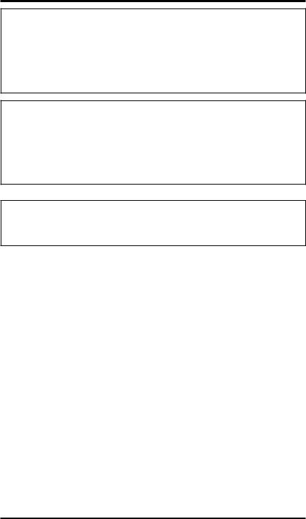
Product
Identification
Upper Louver |
Flue Collar |
|
Panel |
||
|
||
|
Log |
|
Nailing |
Set |
|
Flange |
|
Glass Door
Assembly
Lava
Rock
Lower Louver |
|
|
|
Panel |
|
|
|
Control Valve |
Glowing |
Burner |
|
with Piezo |
Embers |
||
Ignitor |
Assembly |
||
|
Switch Bracket for Optional
Remote and Blower
Figure 1 - Direct-Vent Fireplace with Millivolt Ignition
www.desatech.com |
116192-01E |
Local Codes
Install and use fireplace with care. Follow all local codes. In the absence to local codes, use the cur- rent National Fuel Gas Code ANSI Z223.1/NFPA 54* (USA) or the current CSA-B149.1 Installation Code (Canada).
*Available from:
American National Standards Institute, Inc.
1430 Broadway
New York, NY 10018
National Fire Protection Association, Inc.
Batterymarch Park
Quincy, MA 02269
Product Features
These are a few facts that can help you understand and enjoy your direct-vent fireplace:
•The venting system may be routed to the out- side of your home in several ways. It may vent through the roof (vertical) or it may vent to an outside/exterior wall (horizontal). The vent pipe installation is very important to allow for proper operation. You must follow the venting instructions very carefully for either vertical or horizontal applications.
•This fireplace may be installed in any room of your house provided all local codes and these installation instructions are followed.
•This fireplace requires a wall switch, hand-held remote or wall thermostat (millivolt) for opera- tion (see Accessories, page 42).
•This fireplace does not require electricity to operate.
•Only the blower requires electricity if installed and if you plan to install the blower at a later date, do not forget to wire the outlet at the bot- tom of the fireplace when framing.
•A piezo ignitor and ceramic electrode create spark to ignite the pilot light. It does not require any matches, batteries or any other sources of ignition to light the pilot.
•Each time you turn on your fireplace, you may notice some amount of condensation on the in- sideofthefireplaceglass.Thisisnormalandwill disappear after 10-20 minutes of operation.
•Your direct-vent gas fireplace system (fireplace and venting) is a balanced and sealed gas op- erating unit. It requires approximately 10-20 minutes of operating time before the flame pattern stabilizes.
•Fireplaces with the suffix of -HA have been designed to operate at altitudes of 4000 feet and above.
Pre-Installation
Preparation
Location and space
requirements
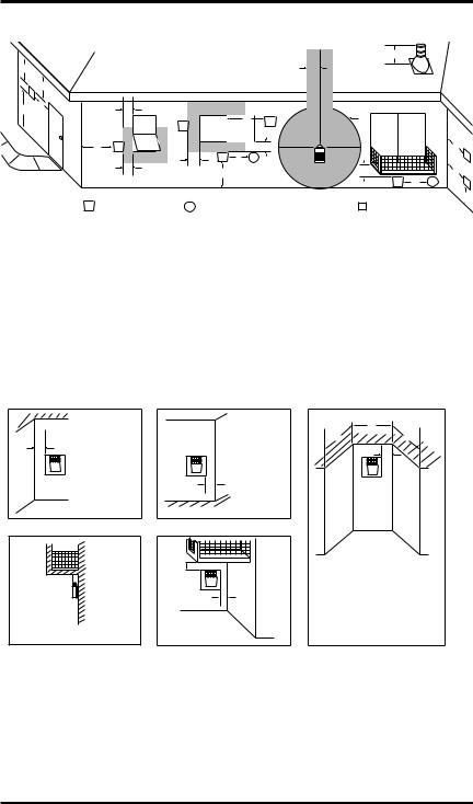
Determine the safest and most efficient location for your DESA direct-vent fireplace. Make sure that rafters and wall studs are not in the way of the venting system. Choose a location where the heat output is not affected by drafts, air conditioning ducts, windows or doors. Figure 2 shows some common locations. Beawareof all restrictions and precautions before deciding the exact location for your fireplace and termination cap.
When deciding the location of your fireplace, follow these rules:
•Do not connect this fireplace venting to a chim- ney flue serving a separate solid-fuel burning fireplace or appliance.
•Due to high temperatures, do not locate this fireplace in high traffic areas, windy or drafty areas or near furniture or draperies.
•Proper clearances must be maintained.
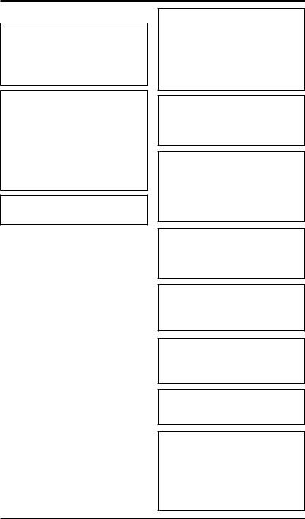
•If your fireplace is to be installed directly on carpeting, vinyl tile or any combustible mate- rial other than wood, it must be installed on a metal or wood panel extending the full width and depth of the fireplace. See Figure 3.
Flush with a wall
Through exterior wall enclosed in a chase
Corner installation
Figure 2 - Common Fireplace Locations
RW29"
21D1/8"
FW41"
Figure 3 - Fireplace Bottom Dimensions
116192-01E |
www.desatech.com |
Pre-Installation
Preparation
Continued
•Your fireplace is designed to be used in zero clearanceinstallations.Wallorframingmaterial can be placed directly against any exterior sur- face on the back, sides or top of your fireplace, except where standoff spacers are integrally attached.Ifstandoffspacersareattachedtoyour fireplace, these spacers can be placed directly against wall or framing material. See framing details on page 7.
•If you plan on installing a television or enter- tainmentcenterrecessedaboveyourfireplace,it is recommended that you maintain a minimum 18" above top of louver opening.
•When locating termination cap, it is important to observe the minimum clearances shown in Figure 7, page 8.
•If recessing into a wall, you can avoid extra framing by positioning your fireplace against an already existing framing member.
•Do not recess termination cap into a wall or siding.
•You may paint the termination cap with 450ºF (232ºC) heat-resistant paint to coordinate with the exterior finish.
•There must not be any obstruction such as bushes, garden sheds, fences, decks or util- ity buildings within 24" from the front of the termination cap.
•Do not locate termination cap where excessive snow or ice build up may occur. Be sure to clear vent termination area after snow falls to prevent accidental blockage of venting system. When using snow blowers, do not direct snow towards vent termination area.
Clearances
Minimum clearances to combustibles for the fire- |
|
place are as follows: |
|
*Back and sides |
0"/mm |
Perpendicular walls |
6" (152 mm) |
Floor |
0"/mm |
Ceiling to louver opening |
42" (1067 mm) |
Front |
36" (914 mm) |
Top of Standoffs |
0"/mm |
Vent |
(See venting |
|
instructions for specific |
|
venting clearances.) |
Combustible material with a maximum thick- ness of 5/8" may be flush with the top front of fireplace.
* For back and sides of fireplace, do not pack with insulation or other materials. Zero inch clearance to combustible materials are for fram- ing purpose only.
NOTICE: This fireplace is intended for use as supplemental heat. Use this fireplace along with your primary heating system. Do not install this fireplace as your primary heat source. If you have a central heating system, you may run system’s circulating blower while using fireplace.Thiswillhelpcirculate the heat throughout the house.
In the event of a power outage, you can use this fireplace as a heat source.
www.desatech.com |
116192-01E |

Pre-Installation
Preparation
Continued
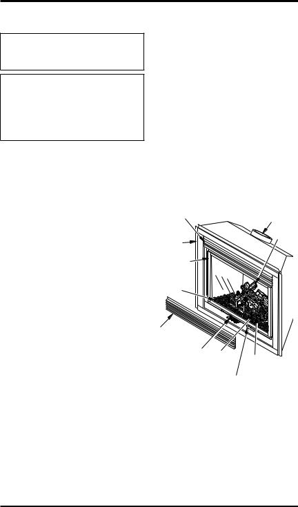
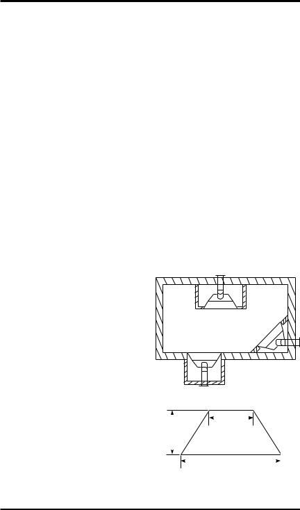
framing and finishing
Figure 4 shows typical framing of this fireplace. Figure 5 shows framing for corner installation. All minimum clearances must be met.
For available accessories for this fireplace, see Accessories on page 42. If you are using a sepa- rate combustible mantel piece, refer to Figure 6 for proper installation height. You can install noncombustible mantels at any height above the fireplace.
Note: Noncombustible mantels may discolor!
|
1 |
|
|
|
2 |
|
|
A |
3 |
|
|
4 |
Wall |
||
|
|||
|
|
||
B |
5 |
|
|
C |
6 |
|
|
D E |
|
||
7 |
|
||
F |
G |
|
Top of Louver
Opening
|
|
|
|
|
|
|
|
|
|
|
Mantel from |
|
|
|
36 1/8" |
|
|
|
|
|
|
|
Top of Louver |
|
|
|
|
|
|
|
Ref. |
Mantel Depth |
Ref. |
Opening |
|
|
|
|
|
|
|
|
|
1 |
14" (356 mm) |
A |
16" (406 mm) |
|
|
|
41 1/4" |
|
|
|
|
2 |
12" (305 mm) |
B |
14" (356 mm) |
|
|
|
|
|
|
|
3 |
10" (254 mm) |
C |
12" (305 mm) |
|
|
|
|
|
|
|
|
|
||||
|
|
|
|
21" Horizontal Vent |
4 |
8" (203 mm) |
D |
10" (254 mm) |
|||
|
|
|
|
5 |
6" (152 mm) |
E |
8" (203 mm) |
||||
|
|
|
|
24 1/2" Vertical Vent |
|||||||
|
|
Figure 4 - Framing Clearances for |
6 |
4" (101 mm) |
F |
6" (152 mm) |
|||||
|
|
7 |
2" (51 mm) |
G |
4" (101 mm) |
||||||
|
Installation Against an Exterior Wall |
||||||||||
|
|
|
|
|
|
|
|
Figure 6 - Clearances for Combustible |
|||
|
|
|
|
|
|
|
|
|
Mantels |
|
|
35 |
|
/ |
B15" |
D |
103/8" |
C 49 5/8" |
|
|
|
|
|
3 |
" |
|
|
|
|
|
|
|
|
||
A |
4 |
|
|
|
|
|
|
|
|
|
|
|
|
|
E |
133/4" |
|
|
|
|
|
|
|
|
|
|
|
F |
41" |
NailingNailingT |
|
|
|
||
|
|
|
|
G |
41 / " |
|
|
|
|||
|
|
|
|
|
1 |
4 |
|
|
|
|
|
|
|
|
|
H 681/2" |
Tabs |
|
|
|
|
||
|
|
|
|
|
|
|
|
|
|||
Figure 5 - Framing Clearances for Corner |
|
|
|
|
|||||||
|
|
|
|
Installation |
|
|
|
|
|
||
116192-01E |
www.desatech.com |
Location of Termination Cap
D
E
V
B L
|
|
|
|
|
|
H |
|
C |
|
|
|
|
|
|
Fixed |
|
|
B |
V |
I |
|
Closed |
V |
Openable |
Fixed |
|
|
|
Openable |
|
|
Closed |
|
|
F |
|
|
|
B |
|
|
V |
|
|
|
|
|
B |
V J |
X |
G |
|
|
|
|
|
B |
|
A |
|
M |
|
|
|
N  N
N 
|
G |
|
V |
|
G |
V K X |
V |
|
|
|
|
|
A |
||
V TERMINATION CAP |
X AIR SUPPLY INLET |
G |
GAS METER |
|
RESTRICTED AREA |
|
|
|
|||||||
|
|
|
|
|
(TERMINATION PROHIBITED) |
||
A= clearance above grade, veranda, porch, deck, or balcony [*12 inches (30.5mc) minimum]
B= clearance to window or door that may be opened
[12 inches (30.5cm) minimum]
C = clearance to permanently closed window [minimum 12 inches (30.5cm) recommended to prevent condensation on window]
D = vertical clearance to ventilated soffit located above the terminal within a horizontal distance of 24 inches (61cm) from the center-line of the terminal [18 inches (45.7cm) minimum]
E= clearance to unventilated soffit [12 inches (30.5cm) minimum]
F= clearance to outside corner (see below)
G= clearance to inside corner (see below)
H= *not to be installed above a meter/regulator assembly within
36 inches (91.4cm) horizontally from the center-line of the regulator
I= clearance to service regulator vent outlet [*72 inches (182.9cm) minimum]
J= clearance to non-mechanical air supply inlet to building or the combustion air inlet to any other fireplace [*12 inches (30.5cm) minimum]
K= clearance to a mechanical air supply inlet [*72 inches (182.9cm) minimum]
L= † clearance above paved side-walk or a paved driveway located on public property [*84 inches (213.3cm) minimum]
M= clearance under veranda, porch, deck [*12 inches (30.5cm) minimum ‡]
N= clearance above a roof shall extend a minimum of 24 inches (61cm) above the highest point when it passes through the roof surface and any other obstruction within a horizontal distance of 18 inches (45.7cm)
† vent shall not terminate directly above a side-walk or paved driveway which is located between two single family dwellings and serves both dwellings*
‡ only permitted if veranda, porch, deck or balconey is fully open on a minimum of 2 sides beneath the floor* * as specified in CAN/CSA B149 (.1 or .2) Installation Codes (1991) for Canada and U.S.A.
Note: Local codes or regulations may require different clearances
Termination Clearances for Buildings with Combustible and Noncombustible Exteriors
Inside Corner |
Outside Corner |
Recessed Location |
|
|
|
D |
|
|
|
C |
C |
A |
A = 6" (15.2cm) |
|
E |
|
|
|
|
V |
V |
V |
|
|
B |
B = 6" (15.2cm) |
|
Balcony with No Side Wall |
Balcony with Perpendicular Side Wall |
|
H |
|
G |
V |
|
|
||
V |
J |
|
|
||
|
Combustible & |
|
|
Noncombustible |
|
G = 12" (30.5cm) minimum clearance |
H = 24" (61cm) |
|
J = 20" (50.8cm) |
||
|
C = Maximum depth of 48" (121.9cm) for recessed location
D = Minimum width for back wall of recessed location - Combustible - 38" (965mm) Noncombustible - 24" (61cm)
E = Clearance from corner in recessed locationCombustible - 6" (15.2cm) Noncombustible - 2" (5.1cm)
Figure 7 - Minimum Clearances for Termination Cap
www.desatech.com |
116192-01E |
Venting Installation
Instructions
NOTICE: Read these instructions completely before attempting installation.
These models are tested and approved for use with DESA (direct-vent) pipe components and terminations.
Theventingsystemmustterminateontheoutsideof the structure and can not be attached to a chimney or flue system serving a separate solid fuel or gas burning appliance. A direct-vent appliance must have its own venting system. DO NOT common vent this appliance.
These models are approved to be vented either horizontally through an outside wall or vertically through a roof or chase enclosure using the fol- lowing guidelines:
•When venting system terminates horizontally on an outside wall, you may install a standoff if the termination cap is to be installed directly on a combustible finish such as vinyl, wood, stucco, etc.
•Never run the vent downward as this may cause excessive temperatures which could cause a fire.
•Vent pipe air space clearances to combustibles are 1" on all sides except on the horizontal sections, which requires 2" clearance from the top of the pipe. Where the termination cap penetrates a combustible wall, 1" air space clearance is required.
•Snorkel terminations are required when minimum clearance to grade cannot be met (see Figure 16 on page 13).
•Havefireplaceandselectedventcomponentson hand to help determine the exact measurements when elbowing or offsetting. Always use wall firestops when penetrating walls and firestops when penetrating ceilings or attic spaces.
•Install horizontal venting with a 1/4" rise for every 12" of run toward the termination.
•Forinstallationoffireplaceatelevationsof4000 feet or greater, pay special attention to venting requirement recommendations.
 WARNING: Read all instructionscompletelyandthoroughly before attempting installation.
Failure to do so could result in seriousinjury,propertydamage or loss of life.
NOTICE:Failuretofollowtheseinstructions will void the warranty.
NOTICE:Donotsealtermination cap to vent pipe. Cap must be removable for vent inspection and maintenance.
Installation Precautions
•Wear gloves and safety glasses for protection
•Use extreme caution when using ladders or when on roof tops
•Be aware of electrical wiring locations in walls and ceilings
The following actions will void the warranty on your venting system:
•Installation of any damaged venting component
•Unauthorized modification of the venting sys- tem (Do not cut or alter vent components)
•Installation of any component part not manu- factured or approved by DESA
•Installation other than as instructed by these instructions
 WARNING: This gas fireplace andventassemblymustbevented directlytotheoutside.Theventing system must NEVER be attached to a chimney serving a separate solidfuelburningappliance.Each direct-vent gas appliance must useaseparateventsystem.Donot use common vent systems.
 WARNING: Vent pipe air spaceclearancestocombustibles are 1" on all sides except on the horizontalsections,whichrequire 2" clearances from the top of the pipe. Where the termination cap penetratesacombustiblewall,1" air space clearance is required.
116192-01E |
www.desatech.com |
Venting Installation instructions
Continued
INSTALLATION PLANNING
There are two basic types of direct-vent in- stallation:
•Horizontal Termination
•Vertical Termination
Horizontal Termination Installation
IMPORTANT: Horizontal square terminations require only inner portion of wall firestop. Hori- zontalinstallationsusingroundterminationrequire exterior portion of wall firestop (see Figure 14, page 12).
1.Setthefireplaceinitsdesiredlocationanddeter- minetherouteyourhorizontalventingwilltake. Do not secure the fireplace until all venting has beeninstalled.Someinstallationsrequiresliding thefireplaceinandoutofpositiontomakefinal venting connections. Figures 14 through 18 on pages 12 through 14 show different configura- tionsforventingwithhorizontalterminationthat willhelpyoudecidewhichapplicationbestsuits your installation. Check to see if wall studs or roof rafters are in the path of your desired vent- ingroute.Iftheyare,youmaywanttoadjustthe location of the fireplace.
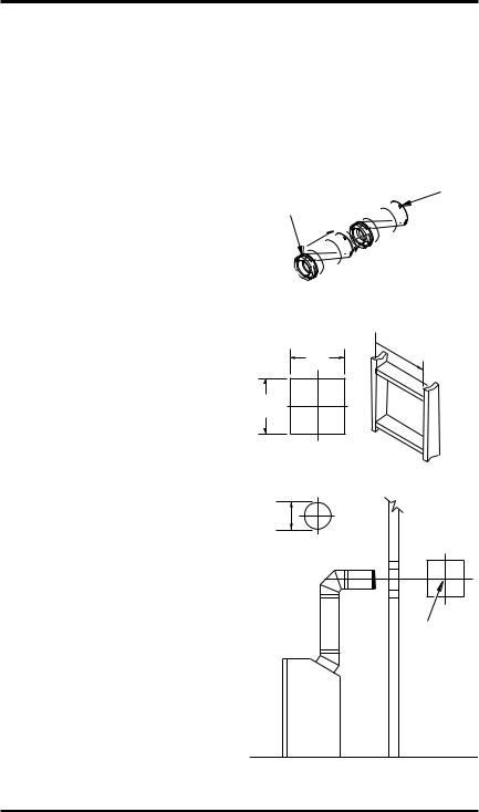
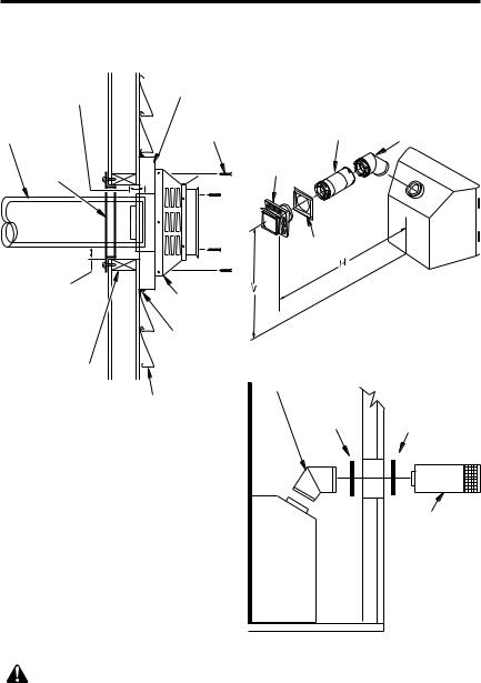
2.Direct vent pipe sections and components are designed with special twist-lock connections.
Twist-Lock Procedure: The female ends of the pipes have locking lugs (indentations). These lugs will slide straight into matching slots on the male ends of adjacent pipes. Push pipe sec- tions together and twist one section clockwise approximatelyone-quarterturnuntilthesections arefullylocked(seeFigure8).Note: Horizontal runs of vent must be supported every three feet. Use wall straps for this purpose.
3.Use a 45° elbow to connect venting system to fireplace flue collar. The elbow is designed to be twist-locked onto the flue collar as described in step 2. IMPORTANT: Do not attempt to alter the configuration of the elbow by cutting, twisting, bending, etc.
4.Assemblethedesiredcombination of pipe and elbows to the fireplace flue collar. If there are long portions of venting run, pre-assembled pipe sections may be installed as subassem- blies for convenience.
5.Carefullydeterminethelocationwherethevent pipe assembly will penetrate the outside wall. The center of the hole should line up with the center-lineofthehorizontalventpipe.Markthe wall for a 10 3/4" x 10 3/4" square hole. Cut and framethesquareholeintheexteriorwallwhere the vent will be terminated. If the wall being penetrated is constructed of noncombustible material, such as masonry block or concrete, a 8 1/2" hole with zero clearance is acceptable (see Figure 9).
Female |
Male |
|
Slots |
||
Locking Lugs |
||
|
Figure 8 - Vent Pipe Connections
Vent Opening
Combustible Wall  10 3/4" Inside Framing
10 3/4" (273 mm)
(273 mm)
10 3/4"
(273 mm)
(Framing
Vent Opening Detail)
Noncombustible Wall
Center of |
Hole |
Figure 9 - Vent Opening Requirements
10 |
www.desatech.com |
116192-01E |
Venting Installation
instructions
Continued
 WARNING: Do not recess vent termination into any wall. This will cause a fire hazard.
6.Noncombustible Exterior Wall: Position the horizontal vent cap in the center of the 8 1/2" round hole and attach to the exterior wall with four wood screws provided. Before attaching the vent cap to exterior wall, run a bead of non-hardening mastic (pliable sealant) around theoutsideedgestomakeasealbetweenitand the outside wall. Note: The four wood screws provided should be replaced with appropriate fasteners for stucco, brick, concrete or other types of sidings.
Combustible Exterior Wall: For vinyl siding, stuccoorwoodexteriors,asidingstandoffmay be installed between the vent cap and exterior wall. The siding standoff prevents excessive heat from damaging the siding materials. Siding material must be cut to accommodate standoff. Bolt the vent cap to the standoff.Ap- ply non-hardening mastic around outside edge ofstandoff.Positionthestandoff/capassembly inthecenterofthe103/4"squareholeandattach toexteriorwallwithwoodscrewsprovided(see Figure 11). The siding standoff must sit flush against the exterior fascia material.
7.CombustibleExteriorWallOnly:Slidethewall firestop over the vent pipe before connecting horizontal run to vent cap (see Figure 12).
8.Carefully move fireplace, with vent assembly attached, toward wall and insert vent pipe into horizontal termination. The pipe overlap should be a minimum of 11/4" (see Figure 13, page 12).
9.Combustible Exterior Wall Only: Slide wall firestopagainstinteriorwallsurfaceandattach with screws provided. See Figure 13, page 12, for horizontal termination details.
10.Place fireplace into position and shim with noncombustible material if needed. Nail or screw side flanges to framing to secure unit in place. IMPORTANT: Make sure fireplace is level before securing. If fireplace is not level it will not work properly.
Vent Cap
Wood Screw
Figure 10 - Installing Horizontal Vent Cap
(Noncombustible Exterior)
Cut Siding Away to
Fit Standoff
Standoff Wood
Screw
Vent
Cap
Apply Mastic |
Screws |
|
to All Four Sides |
||
|
Figure 11 - Installing Siding Standoff
(Combustible Exterior Wall)
Interior Wall
Surface
Wall
Firestop
Vent Cap (Horizontal Termination)
Screw Horizontal Vent Pipe
Figure 12 - Connecting Vent Cap with Horizontal Vent Pipe
116192-01E |
www.desatech.com |
11 |
Venting Installation |
GROUND FLOOR INSTALLATION |
||||||||
|
|
instructions |
Recommended Applications: |
|
|||||
|
|
• Installation using cabinet surrounds |
|||||||
|
|
|
|
Continued |
|
||||
|
|
|
|
|
• Throughthewallusingroundorsquaretermina- |
||||
|
|
|
|
|
|
|
|||
|
Minimum Pipe |
Siding Standoff |
tion (up to 12" horizontal pipe) |
||||||
|
Overlap 11/4" |
• NOT FOR CORNER INSTALLATION |
|||||||
Direct-Vent |
|
|
|
|
Horizontal |
Adjustable |
|
||
Pipe |
|
|
|
|
|
Screws |
Pipe 12" Max. |
45° Elbow |
|
|
|
|
|
|
High Wind |
||||
|
|
|
|
|
|
|
|
||
|
|
Wall |
|
|
|
|
Square |
|
|
|
|
|
|
|
|
Termination |
|
||
|
|
Firestop |
|
|
|
|
|||
|
|
|
|
|
|
|
|
||
|
|
|
|
|
|
|
Wall Firestop |
|
|
Maintain 1" |
|
|
|
|
|
|
|
||
Minimum Air |
|
|
|
|
|
|
|
||
Space Around |
|
|
High Wind |
|
Square Termination |
||||
Outer Pipe When |
Termination |
|
Vertical (V) |
Horizontal (H) |
|||||
Penetrating a Wall |
Apply |
|
|||||||
|
|
|
|
|
|
|
32 3/4" min. |
17" max. |
|
|
|
|
|
|
|
Mastic to |
|
|
|
10 |
3 |
4 |
3 |
4 |
" |
Outside |
|
|
|
|
/ " x 10 |
|
/ |
Edge of |
|
|
Exterior Portion |
||
Framed Opening |
45° Elbow |
||||||||
|
|
|
|
|
|
Standoff |
of Wall Firestop |
||
|
|
Exterior Wall with Vinyl Siding |
|
Wall |
(Round |
||||
|
|
Figure 13 - Typical Horizontal |
|
Termination |
|||||
|
|
|
Firestop |
Only) |
|||||
|
Termination Cap Mounting with |
|
|||||||
|
|
|
|
||||||
Additional Siding Standoff Installed |
|
|
|
||||||
Horizontal Termination Configurations |
|
|
|
|
|
|
|
|
|
|
|
|
|
||
Figures 14 through 18 show different configura- |
|
|
|
|
|
|
|
tions and alternatives for venting with horizontal |
|
|
|
|
|
|
|
|
|
|
|
|
|
||
termination. Each figure includes a chart with |
|
|
|
|
|
Horizontal |
|
criticalminimumandmaximumdimensionswhich |
|
|
|
|
|
||
|
|
|
|
|
Round |
||
MUST be met. IMPORTANT: Remember that a |
|
|
|
|
|
||
|
|
|
|
|
Termination |
||
horizontal run of venting must have a 1/4" rise for |
|
|
|
|
|
|
|
every 12" of run toward the termination. |
|
|
|
|
|
Round |
|
|
|
|
|
|
|
|
Termination |
NOTICE:Donotsealtermination |
|
||||||
|
|
|
|
|
|
|
|
cap to vent pipe. Cap must be |
|
|
|
|
|
|
|
removable for vent inspection |
|
|
|
|
|
|
|
and maintenance. |
|
* If installing this fireplace at altitudes of |
|||||
|
|
||||||
|
|
4000 feet and above, it is recommended |
|||||
|
|
||||||
WARNING: Never run vent |
|
that an additional vertical height of 6" be |
|||||
downward as this may cause |
|
added to the vent system. |
|||||
|
Figure 14 - Horizontal Termination |
||||||
excessive temperatures which |
|
||||||
could cause a fire. Operation of |
|
Configuration for Square or Round |
|||||
improperly installed and main- |
|
Terminations |
|||||
|
|
|
|
|
|
|
|
tained venting system could |
|
|
|
|
|
|
|
resultinseriousinjury,property |
|
|
|
|
|
|
|
damage or loss of life. |
|
|
|
|
|
|
|
|
|
|
|
|
|
|
|
|
|
|
|
|
|
|
|
12 |
www.desatech.com |
116192-01E |
Venting Installation instructions
Continued
CORNER INSTALLATION |
|
Not to Exceed |
|
|
Recommended Applications: |
|
(H) Limits |
Square |
|
• Corner ground floor installation |
90° Elbow |
Termination |
||
|
|
|
|
|
• Groundfloorinstallationwherepipeventshorizon- |
|
|
|
|
tally through wall (over 12" horizontal pipe) |
|
|
|
|
• Basement installation where one foot clearance |
|
|
|
|
from ground to termination is possible |
|
Wall |
|
|
|
90° Elbow |
|
12" Min. |
|
Not to Exceed (H) Limits |
|
Firestop |
||
|
|
|
||
Square |
As Required |
|
|
|
Termination |
|
|
|
|
for (V), See |
|
|
|
|
|
|
|
|
|
|
Chart for |
45° Elbow |
|
|
|
Pipe Section |
|
||
|
|
|
|
|
|
Required |
|
|
|
Wall |
|
|
|
|
Firestop |
|
|
|
|
|
|
|
Required |
|
45° Elbow |
|
Vertical (V) |
Vertical Pipe |
Horizontal (H) |
|
|
*43 1/2" min. |
None |
30" max. |
|
|
54 1/2" min. |
1 ft. |
48" max. |
|
|
66 1/2" min. |
2 ft. |
60" max. |
|
|
78 1/2" min. |
3 ft. |
84" max. |
|
|
90 1/2" min. |
4 ft. |
20' max. |
|
|
* Ground Floor Corner Venting |
|
|
Figure 15 - Horizontal Termination Configuration for Corner Installation Using One
90° Elbow
SNORKEL TERMINATION INSTALLATION
Recommended Applications:
•Installations requiring a vertical rise on building exterior
•Any installation using snorkel termination to achieve one foot above ground
Snorkelterminationsareavailableforinstallationsrequiringaverticalriseontheexteriorofthebuilding. If installing snorkel termination below grade, you must provide proper drainage to prevent water from entering snorkel termination (see Figure 16). Do not back fill around snorkel termination.
Snorkel Termination
|
Snorkel Termination |
Wall |
|
|
Firestop |
Snorkel Termination |
90° Elbow |
|
12" |
Min. |
12" Min.
12" Min.
45° Elbow
Adequate
Drainage
Figure 16 - Snorkel Termination Configurations for Below Ground Installation
116192-01E |
www.desatech.com |
13 |
Venting Installation instructions
Continued
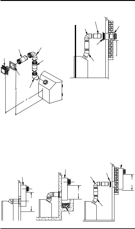
HORIZONTAL SYSTEM INSTALLATION
USING TWO 90° ELBOWS
The following configurations show the minimum vertical rise requirements for a horizontal system using two 90° elbows.
45° Elbow
Venting with Two 90° Elbows
|
|
Horizontal (H1) + |
Vertical (V) |
Horizontal (H1) |
Horizontal (H2) |
5' min. |
2' max. |
6' max. |
6' min. |
4' max. |
12' max. |
7' min. |
6' max. |
18' max. |
8' min. |
8' max. |
20' max. |
20' max. |
8' max. |
20' max. |
Figure 17 - Horizontal Termination Configuration for Venting Using Two 90° Elbows
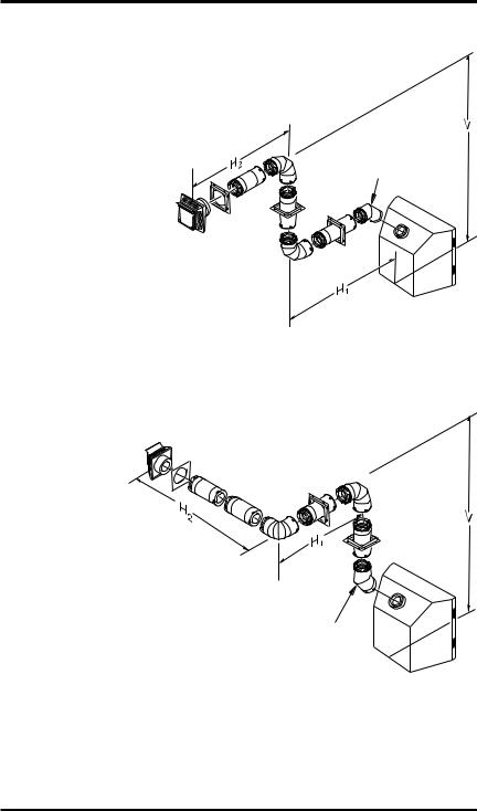
Venting with Two 90° Elbows |
|
||
Vertical (V) |
Horizontal (H1) + |
|
|
Horizontal (H2) |
|
||
|
|
||
5' min. |
6' max. |
|
|
6' min. |
12' max. |
|
|
7' min. |
18' max. |
45° Elbow |
|
8' min. |
20' max. |
||
|
|||
20' max. |
20' max. |
|
|
Figure 18 - Horizontal Termination Configuration for Venting Using Two 90° Elbows with Termination at 90° with Fireplace
14 |
www.desatech.com |
116192-01E |
Loading...