


S26NTA
Save this manual for future reference.
For more information, visit www.desatech.com
WARNING: If the information in this manual is not
followed exactly, a fire or explosion may result causing
property damage, personal injury, or loss of life.
— Do not store or use gasoline or other flammable
vapors and liquids in the vicinity of this or any other
appliance.
— WHAT TO DO IF YOU SMELL GAS
• Do not try to light any appliance.
• Do not touch any electrical switch; do not use any
phone in your building.
• Immediately call your gas supplier from a neighbor’s
phone. Follow the gas supplier’s instructions.
• If you cannot reach your gas supplier, call the fire
department.
— Installation and service must be performed by a quali-
fied installer, service agency, or the gas supplier.
VENT-FREE FREESTANDING PEDESTAL STOVE SYSTEM
OWNER’S OPERATION AND INSTALLATION MANUAL
THERMOSTATICALLY - CONTROLLED MODELS
S26PTA AND S26NTA
20,000 TO 26,000 BTU/HR

www.desatech.com 110361-01E
2
WARNING: Improper installation, adjustment, altera-
tion, service, or maintenance can cause injury or prop-
erty damage. Refer to this manual for correct installation
and operational procedures. For assistance or addi-
tional information consult a qualified installer, service
agency, or the gas supplier.
WARNING: This is an unvented gas-fired heater. It uses
air (oxygen) from the room in which it is installed.
Provisions for adequate combustion and ventilation air
must be provided. Refer to
Air for Combustion and
Ventilation
section on page 5 of this manual.
This appliance may be installed in an aftermarket,*
permanently located, manufactured (mobile) home,
where not prohibited by local codes.
This appliance is only for use with the type of gas
indicated on the rating plate. This appliance is not
convertible for use with other gases.
TABLE OF CONTENTS
Safety Information ............................................... 3
Product Identification .......................................... 4
Local Codes ........................................................ 5
Unpacking ........................................................... 5
Product Features ................................................ 5
Air For Combustion And Ventilation .................... 5
Installation ........................................................... 7
Operating Heater .............................................. 14
Inspecting Burners ............................................ 15
Cleaning and Maintenance ...............................16
Specifications .................................................... 17
Service Hints ..................................................... 17
T echnical Service.............................................. 17
Troubleshooting ................................................18
Illustrated Parts Breakdown and Parts List ....... 22
Replacement Parts ........................................... 26
Accessories.......................................................26
Parts Central ..................................................... 27
Warranty Information.......................... Back Cover
www.desatech.com
110361-01E 3
SAFETY INFORMATION
WARNING: This product con-
tains and/or generates chemicals
known to the state of California
to cause cancer or birth defects,
or other reproductive harm.
IMPORTANT: Read this owner’s
manual carefully and completely
before trying to assemble, oper-
ate, or service this heater. Im-
proper use of this heater can
cause serious injury or death
from burns, fire, explosion, elec-
trical shock, and carbon mon-
oxide poisoning.
DANGER: Carbon monoxide
poisoning may lead to death!
Carbon Monoxide Poisoning: Early signs of car-
bon monoxide poisoning resemble the flu, with head-
aches, dizziness, or nausea. If you have these signs,
the fireplace may not be working properly. Get fr esh
air at once! Have fireplace serviced. Some people
are more affected by carbon monoxide than others.
These include pregnant women, people with heart
or lung disease or anemia, those under the influence
of alcohol, and those at high altitudes.
Natural and Propane/LP Gas:
Natural and Propane/LP
gases are odorless. An odor-making agent is added to
these gases. The odor helps you detect a gas leak.
However, the odor added to the gas can fade. Gas
may be present even though no odor exists.
Make certain you read and understand all warn-
ings. Keep this manual for reference. It is your
guide to safe and proper operation of this fireplace.
WARNING: Any change to
this fireplace or its controls can
be dangerous.
WARNING: Do not allow fans
to blow directly into the heater.
Avoid any drafts that alter burner
flame patterns. Ceiling fans can
create drafts that alter burner
flame patterns. Altered burner
patterns can cause sooting.
WARNING: Do not use a
blower insert, heat exchanger
insert, or other accessory not
approved for use with this
heater.
Due to high temperatures, the
appliance should be located out
of traffic and away from furni-
ture and draperies.
Do not place clothing or other
flammable material on or near
the appliance. Never place any
objects in the fireplace.
Heater becomes very hot when
running fireplace. Keep children
and adults away from hot sur-
faces to avoid burns or clothing
ignition. Fireplace will remain
hot for a time after shutdown.
Allow surfaces to cool before
touching.
Carefully supervise young chil-
dren when they are in the room
with fireplace.
You must operate this heater
with the heater screen in place.
Make sure heater screen is in
place before running heater.
Keep the appliance area clear
and free from combustible ma-
terials, gasoline, and other flam-
mable vapors and liquids.
www.desatech.com 110361-01E
4
SAFETY INFORMATION
Continued
1. This appliance is only for use with the type of
gas indicated on the rating plate. This appli-
ance is not convertible for use with other
gases.
2. Do not place propane/LP supply tank(s) in-
side any structure. Locate propane/LP supply
tank(s) outdoors (propane/LP gas units only).
3. If you smell gas
• shut off gas supply
• do not try to light any appliance
• do not touch any electrical switch; do not
use any phone in your building
• immediately call your gas supplier from a
neighbor’s phone. Follow the gas supplier’s
instructions
• if you cannot reach your gas supplier, call
the fire department
4. This heater shall not be installed in a bedroom
or bathroom.
5. Do not use this heater as a wood-burning heater.
Use only the logs provided with the heater.
6. Do not add extra logs or ornaments such as
pine cones, vermiculite, or rock wool. Using
these added items can cause sooting. Do not
add lava rock around base. Rock and debris
could fall into the control area of heater. After
servicing, always replace screen before oper-
ating heater.
7. You must operate this heater with the heater
screen in place. Make sure heater screen is in
place before running heater.
8. This heater is designed to be smokeless. If logs
ever appear to smoke, turn off heater and call
a qualified service person.
Note:
During ini-
tial operation, slight smoking could occur due
to log curing and heater burning manufactur-
ing residues.
9. To prevent the creation of soot, follow the
instructions in Cleaning and Maintenance,
pages 16 and 17.
10. Before using furniture polish, wax, carpet
cleaner, or similar products, turn heater off. If
heated, the vapors from these products may
create a white powder residue within burner
box or on adjacent walls or furniture.
11. This heater needs fresh air ventilation to run
properly. This heater has an Oxygen Deple-
tion Sensing (ODS) safety shutoff system. The
ODS shuts down the heater if not enough fresh
air is available. See Air for Combustion and
Ventilation, pages 5 through 7. If heater keeps
shutting off, see Troubleshooting, pages 18
through 21.
12. Keep all air openings in front and bottom of
heater clear and free of debris. This will in-
sure enough air for proper combustion.
13. Do not run heater
• where flammable liquids or vapors are used
or stored.
• under dusty conditions.
14. Do not use this heater to cook food or burn
paper or other objects.
15. Do not use heater if any part has been under
water. Immediately call a qualified service
technician to inspect the room heater and to
replace any part of the control system and any
gas control which has been under water.
16. Turn off and unplug heater and let cool be-
fore servicing. Only a qualified service per-
son should service and repair heater.
17. Operating heater above elevations of 4,500
feet could cause pilot outage.
18. Do not operate heater if any log is broken. Do
not operate heater if a log is chipped (dime-
sized or larger).
19. To prevent performance problems with pro-
pane/LP units, do not use propane/LP fuel tank
of less than 100 lbs. capacity.
20. Provide adequate clearances around air
openings.
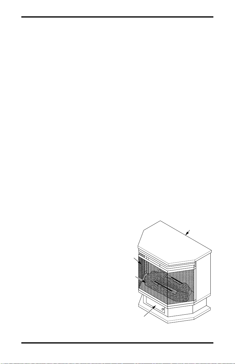
PRODUCT
IDENTIFICATION
Heater Controls
(Inside Door)
Screen
Logs
Stove
Cabinet
Figure 1 - Vent-Free Freestanding
Pedestal Stove
www.desatech.com
110361-01E 5
LOCAL CODES
Install and use heater with care. Follow all local
codes. In the absence of local codes, use the latest
edition of The National Fuel Gas Code, ANSI
Z223.1/NFPA 54*.
*Available from:
American National Standards Institute, Inc.
1430 Broadway
New York, NY 10018
National Fire Protection Association, Inc.
Batterymarch Park
Quincy, MA 02269
UNPACKING
1. Remove top inner pack.
2. Tilt carton so that stove is upright.
3. Remove protective side packaging.
4. Slide stove out of carton.
5. Remove protective plastic wrap.
6. Remove screen by lifting and then pulling
forward.
7. Remove log set by cutting plastic ties.
8. Carefully unwrap log.
9. Check for any shipping damage. If stove or
log is damaged, promptly inform dealer where
you bought stove.
PRODUCT FEATURES
SAFETY PILOT
This heater has a pilot with an Oxygen Depletion
Sensing (ODS) safety shutoff system. The ODS/
pilot is a required feature for vent-free room heat-
ers. The ODS/pilot shuts off the heater if there is
not enough fresh air.
PIEZO IGNITION SYSTEM
This heater has a piezo ignitor. This system re-
quires no matches, batteries, or other sources to
light heater.
AIR FOR COMBUSTION
AND VENTILATION
WARNING: This heater shall
not be installed in a confined space
or unusually tight construction
unless provisions are provided
for adequate combustion and ven-
tilation air. Read the following in-
structions to insure proper fresh
air for this and other fuel-burning
appliances in your home.
Today’ s homes are built more ener gy efficient than
ever. New materials, increased insulation, and new
construction methods help reduce heat loss in
homes. Home owners weather strip and caulk
around windows and doors to keep the cold air out
and the warm air in. During heating months, home
owners want their homes as airtight as possible.
While it is good to make your home energy effi-
cient, your home needs to breathe. Fresh air must
enter your home. All fuel-burning appliances need
fresh air for proper combustion and ventilation.
Exhaust fans, fireplaces, clothes dryers, and fuel
burning appliances draw air from the house to
operate. You must provide adequate fresh air for
these appliances. This will insure proper venting
of vented fuel-burning appliances.
PROVIDING ADEQUATE
VENTILATION
The following are excerpts from National Fuel
Gas Code, ANSI Z223.1/NFP A 54, Section 5.3, Air
for Combustion and Ventilation.
All spaces in homes fall into one of the three fol-
lowing ventilation classifications:
1. Unusually Tight Construction
2. Unconfined Space
3. Confined Space
The information on pages 5 through 7 will help
you classify your space and provide adequate ven-
tilation.
Unusually Tight Construction
The air that leaks around doors and windows may
provide enough fresh air for combustion and ven-
tilation. However, in buildings of unusually tight
construction, you must provide additional fresh air.

www.desatech.com 110361-01E
6
Unusually tight construction is defined as
construction where:
a. walls and ceilings exposed to the out-
side atmosphere have a continuous
water vapor retarder with a rating of
one perm (6 x 10
-11
kg per pa-sec-m
2
)
or less with openings gasketed or
sealed and
b. weather stripping has been added on
openable windows and doors and
c. caulking or sealants are applied to ar-
eas such as joints around window and
door frames, between sole plates and
floors, between wall-ceiling joints, be-
tween wall panels, at penetrations for
plumbing, electrical, and gas lines, and
at other openings.
If your home meets all of these three crite-
ria, you must provide additional fresh air.
See
Ventilation Air From Outdoor s
, page 7
.
If your home does not meet all of the three
criteria above, proceed to
Determining
Fresh-Air Flow For Fireplace Location
.
Confined and Unconfined Space
The National Fuel Gas Code, ANSI Z223.1/NFPA
54 defines a confined space as a space whose vol-
ume is less than 50 cubic feet per 1,000 Btu per
hour (4.8 m
3
per kw) of the aggregate input rating
of all appliances installed in that space and an un-
confined space as a space whose volume is not less
than 50 cubic feet per 1,000 Btu per hour (4.8 m
3
per kw) of the aggregate input rating of all appli-
ances installed in that space. Rooms communicat-
ing directly with the space in which the appliances
are installed*, through openings not furnished with
doors, are considered a part of the unconfined space.
* Adjoining rooms are communicating only if there
are doorless passageways or ventilation grills be-
tween them.
DETERMINING FRESH-AIR FLOW
FOR HEATER LOCATION
Determining if You Have a Confined or
Unconfined Space
Use this work sheet to determine if you have a
confined or unconfined space.
Space: Includes the room in which you will install
heater plus any adjoining rooms with doorless pas-
sageways or ventilation grills between the rooms.
AIR FOR COMBUSTION
AND VENTILATION
Continued
1. Determine the volume of the space (length x
width x height).
Length x Width x Height =__________cu. ft.
(volume of space)
Example:
Space size 20 ft. (length) x 16 ft.
(width) x 8 ft. (ceiling height) = 2560 cu. ft. (vol-
ume of space)
If additional ventilation to adjoining room is sup-
plied with grills or openings, add the volume of
these rooms to the total volume of the space.
2. Multiply the space volume by 20 to determine
the maximum Btu/Hr the space can support.
__________ (volume of space) x 20 = (Maxi-
mum Btu/Hr the space can support)
Example:
2560 cu. ft. (volume of space) x 20 =
51,200 (maximum Btu/Hr the space can support)
3. Add the Btu/Hr of all fuel burning appliances in
the space.
Vent-free fireplace __________ Btu/Hr
Gas water heater* __________ Btu/Hr
Gas furnace __________ Btu/Hr
Vented gas heater __________ Btu/Hr
Gas fireplace logs __________ Btu/Hr
Other gas appliances* + __________ Btu/Hr
Total = __________ Btu/Hr
* Do not include direct-vent gas appliances. Di-
rect-vent draws combustion air from the outdoors
and vents to the outdoors.
Example:
Gas water heater ______________ Btu/Hr
Vent-free fireplace ______________ Btu/Hr
Total ______________ Btu/Hr
4. Compare the maximum Btu/Hr the space can
support with the actual amount of Btu/Hr used.
________
Btu/Hr (maximum the space can support)
________
Btu/Hr (actual amount of Btu/Hr used)
Example:
51,200 Btu/Hr (maximum the space
can support)
56,000 Btu/Hr (actual amount of
Btu/Hr used)
The space in the above example is a confined space
because the actual Btu/Hr used is more than the maxi-
mum Btu/Hr the space can support. You must pro-
vide additional fresh air. Your options are as follows:
A. Rework worksheet, adding the space of an adjoin-
ing room. If the extra space provides an uncon-
fined space, remove door to adjoining room or add
ventilation grills between rooms. See Ventilation
Air From Inside Building, page 7.
B. Vent room directly to the outdoors. See Ventila-
tion Air From Outdoors, page 7.
C. Install a lower Btu/Hr heater, if lower Btu/Hr size
makes room unconfined.
30,000
+ 26,000
= 56,000
www.desatech.com
110361-01E 7
If the actual Btu/Hr used is less than the maximum
Btu/Hr the space can support, the space is an uncon-
fined space. Y ou will need no additional fresh air ven-
tilation.
WARNING: If the area in
which the heater may be oper-
ated is smaller than that defined
as an unconfined space or if the
building is of unusually tight
construction, provide adequate
combustion and ventilation air
by one of the methods described
in the
National Fuel Gas Code,
ANSI Z223.1/NFPA 54 Section
5.3
or applicable local codes
.
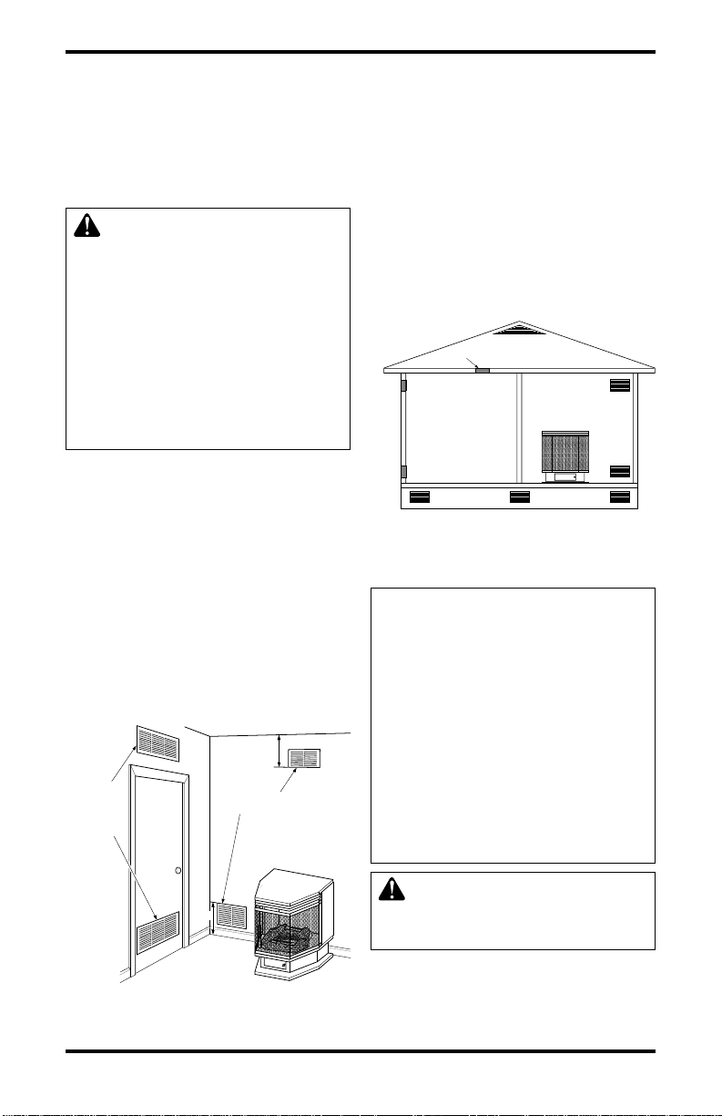
VENTILATION AIR
Ventilation Air From Inside Building
This fresh air would come from an adjoining un-
confined space. When ventilating to an adjoining
unconfined space, you must provide two perma-
nent openings: one within 12" of the ceiling and
one within 12" of the floor on the wall connecting
the two spaces (see options 1 and 2, Figure 2).
Y ou can also remove door into adjoining room (see
option 3, Figure 2). Follow the National Fuel Gas
Code, ANS Z223.1/NFPA 54, Section 5.3, Air for
Combustion and Ventilation for required size of
ventilation grills or ducts.
AIR FOR COMBUSTION
AND VENTILATION
Continued
Ventilation Air From Outdoors
Provide extra fresh air by using ventilation grills
or ducts. You must provide two permanent open-
ings: one within 12" of the ceiling and one within
12" of the floor. Connect these items directly to
the outdoors or spaces open to the outdoors. These
spaces include attics and crawl spaces. Follow the
National Fuel Gas Code, ANS Z223.1/NFPA 54,
Section 5.3, Air for Combustion and Ventilation
for required size of ventilation grills or ducts.
IMPORTANT:
Do not provide openings for inlet
or outlet air into attic if attic has a thermostat-con-
trolled power vent. Heated air entering the attic
will activate the power vent.
Figure 3 - Ventilation Air from Outdoors
Figure 2 - Ventilation Air from Inside
Building
Outlet
Air
Ventilated
Attic
Outlet
Air
Inlet
Air
Inlet Air
Ventilated
Crawl Space
To
Crawl
Space
To Attic
Or
Remove
Door into
Adjoining
Room,
Option
3
Ventilation Grills
Into Adjoining Room,
Option 2
Ventilation
Grills
Into Adjoining
Room,
Option 1
12"
12"
INSTALLATION
NOTICE: This heater is intended
for use as supplemental heat.
Use this heater along with your
primary heating system. Do not
install this heater as your pri-
mary heat source. If you have a
central heating system, you may
run system’s circulating blower
while using heater. This will help
circulate the heat throughout the
house. In the event of a power
outage, you can use this heater
as your primary heat source.
WARNING: A qualified ser-
vice person must install heater.
Follow all local codes.
www.desatech.com 110361-01E
8
12"
Minimum
12"
Minimum
48"
Minimum
Ceiling
Side Wall Side Wall
WARNING: Never install the
heater
• in a bedroom or bathroom
• in a recreational vehicle
• where curtains, furniture,
clothing, or other flammable
objects are less than 42 inches
from the front, top, or sides of
the heater
• in high traffic areas
• in windy or drafty areas
CAUTION: This heater creates
warm air currents. These currents
move heat to wall surfaces next to
heater. Installing heater next to
vinyl or cloth wall coverings or
operating heater where impuri-
ties (such as, but not limited to,
tobacco smoke, aromatic candles,
cleaning fluids, oil or kerosene
lamps, etc.) in the air exist, may
discolor walls or cause odors.
IMPORTANT:
Vent-free heaters add moisture to
the air. Although this is beneficial, installing heater
in rooms without enough ventilation air may cause
mildew to form from too much moisture. See Air
for Combustion and V entilation, pages 5 through 7.
CHECK GAS TYPE
Use correct gas type (natural or propane/LP). If your
gas supply is not correct, do not install heater. Call
dealer where you bought heater for proper type heater.
WARNING: This appliance
is equipped for (natural or pro-
pane/LP) gas. Field conversion
is not permitted.
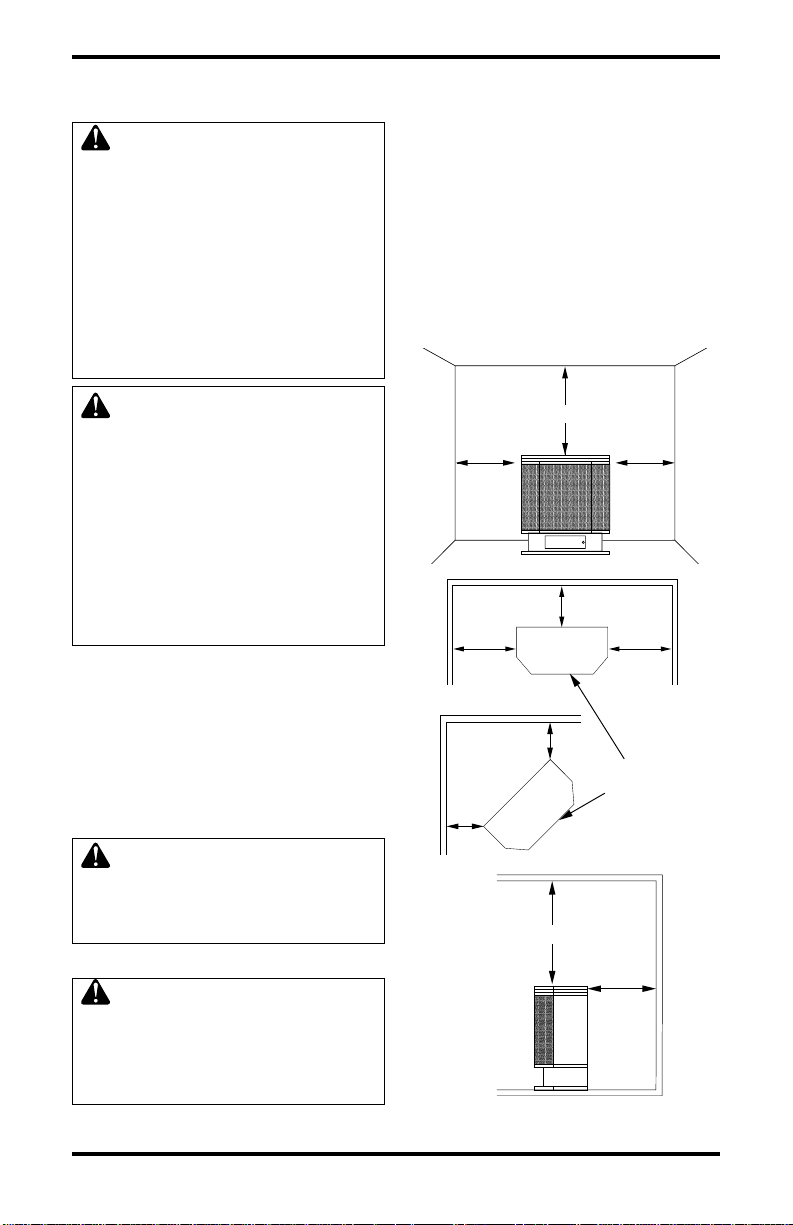
CLEARANCES TO COMBUSTIBLES
WARNING: Maintain the
minimum clearances. If you can,
provide greater clearances from
floor, ceiling, and adjoining side
and back walls.
Carefully follow the instructions below. This stove
is a freestanding unit designed to set directly on
INSTALLATION
Continued
the floor.
IMPORTANT:
You must maintain mini-
mum wall and ceiling clearances during installa-
tion. The minimum clearances are shown in Fig-
ure 4. Measure from outermost point of stove top.
Minimum Wall and Ceiling Clearances
(see Figure 4)
A. Clearances from outermost point of stove top
to any combustible side wall should not be
less than 12 inches.
B. Clearances from outermost point of stove top
to any combustible back wall should not be less
than 6 inches (Includes corner installations).
C. Clearances from the stove top to the ceiling
should not be less than 48 inches.
Figure 4 - Minimum Clearance to Walls
and Ceiling
Front View
Top View
Side View
Front of
Stove Unit
Back Wall
Side Wall Side Wall
12
"
Minimum
12
"
Minimum
6
"
Minimum
6"
Minimum
48"
Minimum
Ceiling
Floor
Back Wall
Corner
Wall
Wall
6
"
Minimum
6
"
Minimum
www.desatech.com
110361-01E 9
CONNECTING TO GAS SUPPLY
WARNING: A qualified ser-
vice person must connect heater
to gas supply. Follow all local
codes.
CAUTION: Never connect
propane/LP heater directly to the
propane/LP supply. This heater
requires an external regulator
(not supplied). Install the exter-
nal regulator between the heater
and propane/LP supply.
WARNING: Never connect
natural gas heater to private (non-
utility) gas wells. This gas is com-
monly known as wellhead gas.
Installation Items Needed
Before installing heater, make sure you have the
items listed below.
• piping (check local codes)
• sealant (resistant to propane/LP gas)
• equipment shutoff valve *
• test gauge connection *
• sediment trap
• tee joint
• pipe wrench
* An CSA design-certified equipment shutoff
valve with 1/8" NPT tap is an acceptable alterna-
tive to test gauge connection. Purchase the optional
CSA design-certified equipment shutoff valve
from your dealer. See Accessories, page 26.
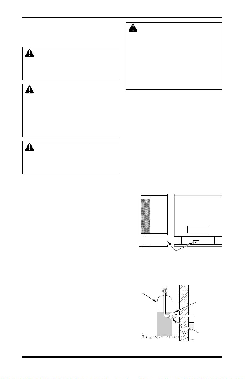
For propane/LP units, the installer must supply an
external regulator. The external regulator will re-
duce incoming gas pressure. You must reduce in-
coming gas pressure to between 11 and 14 inches
of water. If you do not reduce incoming gas pres-
sure, heater regulator damage could occur. Install
external regulator with the vent pointing down as
shown in Figure 6. Pointing the vent down pro-
tects it from freezing rain or sleet.
INSTALLATION
Continued
Figure 5 - Gas Regulator Location and
Gas Line Access Into Stove Cabinet
Front of
Stove
Unit
Gas Regulator
Inlet Connection
Side View
Figure 6 - External Regulator With Vent
Pointing Down
Propane/LP
Supply Tank
External
Regulator
Vent
Pointing
Down
CAUTION: Use only new, black
iron or steel pipe. Internally-tinned
copper tubing may be used in
certain areas. Check your local
codes. Use pipe of 1/2"
diameter
or greater to allow proper gas
volume to heater. If pipe is too
small, undue loss of volume will
occur.
Installation must include an equipment shutoff
valve, union, and plugged 1/8" NPT tap. Locate
NPT tap within reach for test gauge hook up. NPT
tap must be upstream from heater (see Figure 7,
page 10).
IMPORTANT:
Install equipment shutoff valve in
an accessible location. The equipment shutoff
valve is for turning on or shutting off the gas to
the appliance.
Check building codes for any special requirements
for locating equipment shutoff valve to fireplaces.
Apply pipe joint sealant lightly to male NPT
threads. This will prevent excess sealant from go-
ing into pipe. Excess sealant in pipe could result
in clogged heater valves.
 Loading...