


 Loading...
Desa VSL18NT, LSL18NT, VSL18PT, LSL18PT, SL18NT User Manual
...
UNVENTED (VENT-FREE) BLUE FLAME GAS HEATER SAFETY INFORMATION AND INSTALLATION MANUAL
18,000 BTU THERMOSTAT MODELS
LSL18NT, LSL18PT, SL18NT, SL18PT, VSL18NT AND VSL18PT
WARNING: If the information in this manual is not followed exactly, a fire or explosion may result causing property damage, personal injury or loss of life.
—Do not store or use gasoline or other flammable vapors and liquids in the vicinity of this or any other appliance.
—WHAT TO DO IF YOU SMELL GAS
•Do not try to light any appliance.
•Do not touch any electrical switch; do not use any phone in your building.
•Immediatelycallyourgassupplierfromaneighbor’s phone. Follow the gas supplier’s instructions.
•If you cannot reach your gas supplier, call the fire department.
—Installationandservicemustbeperformedbyaqualified installer, service agency or the gas supplier.
Save this manual for future reference. For more information, visit www.desatech.com
WARNING: Improper installation, adjustment, alteration, service or maintenance can cause injury or propertydamage.Refertothismanualforcorrectinstallation and operational procedures. For assistance or additional information consult a qualified installer, service agency or the gas supplier.
WARNING: This is an unvented gas-fired heater. It uses air (oxygen) from the room in which it is installed. Provisions for adequate combustion and ventilation air must beprovided.RefertoAirforCombustionandVentilation section on page 5 of this manual.
This appliance may be installed in an aftermarket,* permanently located, manufactured (mobile) home, where not prohibited by local codes.
This appliance is only for use with the type of gas indicated on the rating plate. This appliance is not convertible for use with other gases.
*Aftermarket: Completion of sale, not for purpose of resale, from the manufacturer
State of Massachusetts: The installation must be made by a licensed plumber or gas fitter in the Commonwealth of Massachusetts.
Sellers of unvented propane or natural gas-fired supplemental room heaters shall provide to each purchaser a copy of 527 CMR 30 upon sale of the unit.
Vent-free gas products are prohibited for bedroom and bathroom installation in the Commonwealth of Massachusetts.
TABLE OF CONTENTS
Safety Information ............................................... |
3 |
Specifications .................................................... |
22 |
Local Codes ........................................................ |
4 |
Wiring Diagrams................................................ |
22 |
Product Identification........................................... |
4 |
Accessories....................................................... |
23 |
Unpacking ........................................................... |
4 |
Technical Service .............................................. |
23 |
Product Features................................................. |
4 |
Service Publications.......................................... |
23 |
Air For Combustion And Ventilation..................... |
5 |
Replacement Parts............................................ |
23 |
Installation ........................................................... |
7 |
Service Hints ..................................................... |
23 |
Operating Heater............................................... |
14 |
Illustrated Parts Breakdown and Parts List ....... |
24 |
Inspecting Heater ............................................. |
16 |
Parts Centrals.................................................... |
26 |
Cleaning and Maintenance................................ |
17 |
Warranty Information......................................... |
28 |
Troubleshooting................................................. |
18 |
|
|
2 |
www.desatech.com |
116292-01D |
SAFETY INFORMATION
 WARNING:Thisproductcontainsand/orgenerateschemicals known to the State of California to cause cancer or birth defects or other reproductive harm.
IMPORTANT: Read this owner’s manualcarefullyandcompletely before trying to assemble, operate or service this heater.
Improper use of this heater can cause serious injury or death from burns, fire, explosion, electrical shock and carbon monoxide poisoning.
 DANGER:Carbonmonoxide
poisoning may lead to death!
CarbonMonoxidePoisoning:Earlysignsofcarbon monoxide poisoning resemble the flu, with headaches, dizziness or nausea. If you have these signs, the heater may not be working properly. Get fresh air at once! Have heater serviced. Some people are more affected by carbon monoxide than others. These include pregnant women, people with heart orlungdiseaseoranemia,thoseundertheinfluence of alcohol and those at high altitudes.
Natural and Propane/LP Gas: Natural and propane/LP gases are fuel gases. Fuel gases are odorless.An odor-making agent are added to fuel gases. The odor helps you detect a fuel gas leak. However, the odor added to fuel gas can fade. Fuel gas may be present even though no odor exists.
Make certain you read and understand all warnings. Keep this manual for reference. It is your guide to safe and proper operation of this heater.
 WARNING: Any change to this heater or its controls can be dangerous.
 WARNING: Do not use a blower insert, heat exchanger insertorotheraccessorynotapproved for use with this heater.
Due to high temperatures, the applianceshouldbelocatedout oftrafficandawayfromfurniture and draperies.
Do not place clothing or other
flammable material on or near the appliance. Never place any objects on the heater.
Surface of heater becomes very hot when running heater. Keep children and adults away from hot surface to avoid burns or clothing ignition. Heater will remain hot for a time after shutdown. Allow surface to cool before touching.
Carefully supervise young children when they are in the same room with heater.
Make sure grill guard is in place before running heater.
Keep the appliance area clear and free from combustible materials, gasoline and other flammable vapors and liquids.
1.This appliance is only for use with the type of gasindicatedontheratingplate.Thisappliance is not convertible for use with other gases.
2.Do not place propane/LP supply tank(s) inside any structure. Locate propane/LP supply tank(s) outdoors.
3.Thisheatershallnotbeinstalledinabathroom or a bedroom.
4.If you smell gas
•shut off gas supply
•do not try to light any appliance
•do not touch any electrical switch; do not use any phone in your building
•immediately call your gas supplier from a neighborʼsphone.Followthegassupplierʼs instructions
•if you cannot reach your gas supplier, call the fire department
116292-01D |
www.desatech.com |
3 |
SAFETY INFORMATION
Continued
5.This heater needs fresh, outside air ventilation to run properly. This heater has an Oxygen Depletion Sensing (ODS) safety shutoff system. The ODS shuts down the heater if not enough fresh air is available. See Air for Combustion and Ventilation, page 5.
6.Keep all air openings in front and bottom of heater clear and free of debris.This will insure enough air for proper combustion.
7.If heater shuts off, do not relight until you provide fresh, outside air. If heater keeps shutting off, have it serviced.
8.Do not run heater
•where flammable liquids or vapors are used or stored
•under dusty conditions
9.Before using furniture polish, wax, carpet cleaner or similar products, turn heater off. If heated, the vapors from these products may create a white powder residue within burner box or on adjacent walls or furniture.
10.Do not use heater if any part has been under water. Immediately call a qualified service technician to inspect the room heater and to replace any part of the control system and any gas control which has been under water.
11.Turn off and let cool before servicing. Only a qualified service person should service and repair heater.
12.Operating heater above elevations of 4,500 feet (1,371 m) could cause pilot outage.
13.To prevent performance problems, do not use propane/LPfueltankoflessthan100lbs.(45kg) capacity.
14.Provide adequate clearances around air openings.
LOCAL CODES
Install and use heater with care. Follow all local codes. In the absence of local codes, use the latest edition of National Fuel Gas Code, ANSI Z223.1/NFPA 54*.
*Available from:
American National Standards Institute, Inc.
1430 Broadway
New York, NY 10018
National Fire Protection Association, Inc.
Batterymarch Park
Quincy, MA 02269
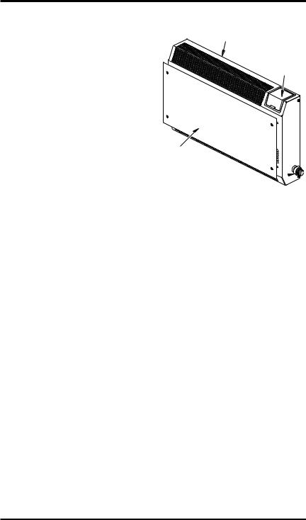
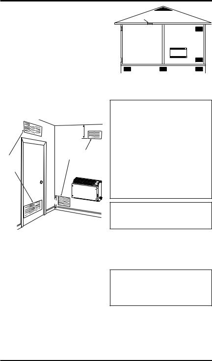
PRODUCT
IDENTIFICATION
Heater Cabinet
Control Knob (under door)
Glass Panel
Ignitor 
Figure 1 - Vent-Free Gas Heater
UNPACKING
1.Remove heater from carton.
2.Remove all protective packaging applied to heater for shipment.
3.Check heater for any shipping damage. If heater is damaged, promptly inform dealer where you bought heater.
PRODUCT FEATURES
SAFETY DEVICE
This heater has a pilot with an Oxygen Depletion Sensing (ODS) safety shutoff system. The ODS/pilot is a required feature for vent-free room heaters.The ODS/pilot shuts off the heater if there is not enough fresh air.
IGNITION SYSTEM
This heater has either a piezo ignitor or electronic ignitor to light heater fuel supply.
THERMOSTATIC HEAT CONTROL
Thermostat models have a thermostat sensing bulb and a control valve. This results in the greatest heater comfort. This can also result in lower gas bills.
4 |
www.desatech.com |
116292-01D |

AIR FOR COMBUSTION AND VENTILATION
 WARNING:Thisheatershall not be installed in a confined space or unusually tight constructionunlessprovisionsare providedforadequatecombustionandventilationair.Readthe followinginstructionstoinsure proper fresh air for this and other fuel-burning appliances in your home.
Todayʼs homes are built more energy efficient than ever. New materials, increased insulation and new construction methods help reduce heat loss in homes. Home owners weather strip and caulk around windows and doors to keep the cold air out and the warm air in. During heating months, home owners want their homes as airtight as possible.
While it is good to make your home energy efficient, your home needs to breathe. Fresh air must enter your home.All fuel-burning appliances need fresh air for proper combustion and ventilation.
Exhaust fans, fireplaces, clothes dryers and fuel burning appliances draw air from the house to operate. You must provide adequate fresh air for these appliances. This will insure proper venting of vented fuel-burning appliances.
PROVIDING ADEQUATE VENTILATION
The following are excerpts from National Fuel Gas Code, ANSI Z223.1/NFPA 54, Section 5.3, Air for Combustion and Ventilation.
All spaces in homes fall into one of the three following ventilation classifications:
1.Unusually Tight Construction
2.Unconfined Space
3.Confined Space
The information on pages 5 through 7 will help you classify your space and provide adequate ventilation.
Unusually Tight Construction
The air that leaks around doors and windows may provide enough fresh air for combustion and ventilation. However, in buildings of unusually tight construction, you must provide additional fresh air.
Unusually tight construction is defined as construction where:
a.walls and ceilings exposed to the outside atmosphere have a continuous water vapor retarder with a rating of one perm (6x10-11 kg per pa-sec-m2) or less with openings gasketed or sealed and
b.weather stripping has been added on openable windows and doors and
c.caulking or sealants are applied to areas such as joints around window and door frames, between sole plates and floors, between wall-ceiling joints, between wall panels, at penetrations for plumbing, electrical and gas lines and at other openings.
If your home meets all of the three criteria above, you must provide additional fresh air. See Ventilation Air From Outdoors, page 7.
If your home does not meet all of the three criteria above, proceed to Determining Fresh-Air Flow For Heater Location, page 6.
Confined and Unconfined Space
The National Fuel Gas Code, ANSI Z223.1/NFPA 54 defines a confined space as a space whose volume is less than 50 cubic feet per 1,000 Btu per hour (4.8 m3 per kw) of the aggregate input rating of all appliances installed in that space and an unconfined space as a space whose volume is not less than 50 cubic feet per 1,000 Btu per hour (4.8 m3 per kw) of the aggregate input rating of all appliances installed in that space. Rooms communicating directly with the space in which the appliances are installed*, through openings not furnished with doors, are considered a part of the unconfined space.
* Adjoining rooms are communicating only if therearedoorlesspassagewaysorventilationgrills between them.
116292-01D |
www.desatech.com |
5 |
AIR FOR COMBUSTION
AND VENTILATION
Continued
DETERMINING FRESH-AIR FLOW FOR HEATER LOCATION
Determining if You Have a Confined or Unconfined Space
Use this work sheet to determine if you have a confined or unconfined space.
Space: Includes the room in which you will install heater plus any adjoining rooms with doorless passageways or ventilation grills between the rooms.
1.Determine the volume of the space (length x width x height).
Length x Width x Height =__________cu. ft. (volume of space)
Example:Space size 20 ft. (6.1 m) (length) x 16 ft.(4.88m)(width)x8ft.(2.44m)(ceilingheight) = 2560 cu. ft. (72.49 m3) (volume of space)
If additional ventilation to adjoining room is supplied with grills or openings, add the volume of these rooms to the total volume of the space.
2.Multiply the space volume by 20 to determine the maximum Btu/Hr the space can support.
_______ (volume of space) x 20 = (Maximum Btu/Hr the space can support)
Example: 2560 cu. ft. (72.49 m3) (volume of space)x20=51,200(maximumBtu/Hrthespace can support)
3.Add the Btu/Hr of all fuel burning appliances in the space.
Vent-free heater |
___________ Btu/Hr |
Gas water heater* |
___________ Btu/Hr |
Gas furnace |
___________ Btu/Hr |
Vented gas heater |
___________ Btu/Hr |
Gas fireplace logs |
___________ Btu/Hr |
Other gas appliances* + __________ |
Btu/Hr |
|
Total |
= __________ |
Btu/Hr |
* Do not include direct-vent gas appliances. Di- rect-ventdraws combustion air from the outdoors and vents to the outdoors.
Example: |
|
|
|
Gas water heater |
|
40,000 |
Btu/Hr |
Vent-free heater |
+ |
18,000 |
Btu/Hr |
Total |
= |
58,000 |
Btu/Hr |
4.Compare the maximum Btu/Hr the space can support with the actual amount of Btu/Hr used.
_________Btu/Hr(maximumthespacecansupport)
_________Btu/Hr (actual amount of Btu/Hr used)
Example: 51,200 Btu/Hr (maximum the space can support)
58,000 Btu/Hr (actual amount of Btu/Hr used)
The space in the above example is a confined space because the actual Btu/Hr used is more than the maximum Btu/Hr the space can support.You must provide additional fresh air. Your options are as follows:
A.Reworkworksheet,addingthespaceofanadjoiningroom.Iftheextraspaceprovidesanunconfined space, remove door to adjoining room or add ventilation grills between rooms. See Ventilation Air From Inside Building, page 7.
B.Vent room directly to the outdoors. See Ventilation Air From Outdoors, page 7.
C.Install a lower Btu/Hr heater, if lower Btu/Hr size makes room unconfined.
If the actual Btu/Hr used is less than the maximum Btu/Hr the space can support, the space is an unconfined space. You will need no additional fresh air ventilation.
 WARNING: If the area in which the heater may be operatedissmallerthanthatdefined as an unconfined space or if the building is of unusually tight construction, provide adequate combustion and ventilation air byoneofthemethodsdescribed in the National Fuel Gas Code, ANSIZ223.1/NFPA54Section5.3 or applicable local codes.
6 |
www.desatech.com |
116292-01D |
AIR FOR COMBUSTION
AND VENTILATION
Continued
VENTILATION AIR
Ventilation Air From Inside Building
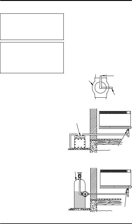
This fresh air would come from an adjoining unconfined space. When ventilating to an adjoining unconfined space, you must provide two permanent openings: one within 12" (30.4 cm) of the ceiling and one within 12" (30.4 cm) of the floor on the wall connecting the two spaces (see options 1 and 2, Figure 2). You can also remove door into adjoiningroom(seeoption3,Figure2).Followthe
National Fuel Gas Code, ANSI Z223.1/NFPA 54, Section5.3,AirforCombustionandVentilation for required size of ventilation grills or ducts.
|
12" |
|
(30.4 cm) |
|
Ventilation Grills |
Ventilation |
Into Adjoining Room, |
Option 2 |
|
Grills |
Or |
into Adjoining |
Remove |
Room, |
Door into |
Option 1 |
Adjoining |
|
Room, |
|
Option 3 |
|
12" |
|
(30.4 cm) |
Figure 2 - Ventilation Air from Inside Building
Ventilation Air From Outdoors
Provide extra fresh air by using ventilation grills or ducts. You must provide two permanent openings: one within 12" (30.4 cm) of the ceiling and one within 12" (30.4 cm) of the floor. Connect these items directly to the outdoors or spaces open to the outdoors. These spaces include attics and crawl spaces. Follow the National Fuel Gas Code, ANSI Z223.1/NFPA 54, Section 5.3, Air for Combustion and Ventilation for required size of ventilation grills or ducts.
IMPORTANT: Do not provide openings for inlet or outlet air into attic if attic has a thermostatcontrolled power vent. Heated air entering the attic will activate the power vent.
|
Outlet |
Ventilated |
|
Attic |
|
|
Air |
|
|
|
|
Outlet |
|
|
Air |
|
To Attic |
|
|
|
|
|
To |
|
|
Crawl |
Inlet |
|
Space |
|
|
|
Air |
|
|
|
Inlet Air |
Ventilated |
|
Crawl Space |
|
|
|
Figure 3 - Ventilation Air from Outdoors
INSTALLATION
NOTICE:Thisheaterisintended for use as supplemental heat. Use this heater along with your primary heating system. Do not install this heater as your primary heat source. If you have a centralheatingsystem,youmay run system’s circulating blower whileusingheater.Thiswillhelp circulatetheheatthroughoutthe house. In the event of a power outage, you can use this heater as your primary heat source.
 WARNING: A qualified service person must install heater. Follow all local codes.
CHECK GAS TYPE
Use only the correct type of gas (natural or propane/LP). If your gas supply is not the correct gas type, do not install heater. Call dealer where you bought heater for proper type heater.
 WARNING: This appliance is equipped for (natural or propane/LP) gas. Field conversion is not permitted.
116292-01D |
www.desatech.com |
7 |
INSTALLATION
Continued
INSTALLATION ITEMS
Before installing heater, make sure you have the items listed below.
•forpropane/LPgas,externalregulator(supplied by installer)
•piping (check local codes)
•sealant (resistant to propane/LP gas)
•equipment shutoff valve *
•ground joint union
•sediment trap
•tee joint
•pipe wrench
•for natural gas, test gauge connection*
*ACSAdesign-certified equipment shutoff valve with 1/8" NPT tap is an acceptable alternative to test gauge connection. The optional CSA designcertifiedequipmentshutoffvalvecanbepurchased from your dealer. See Accessories, page 23.
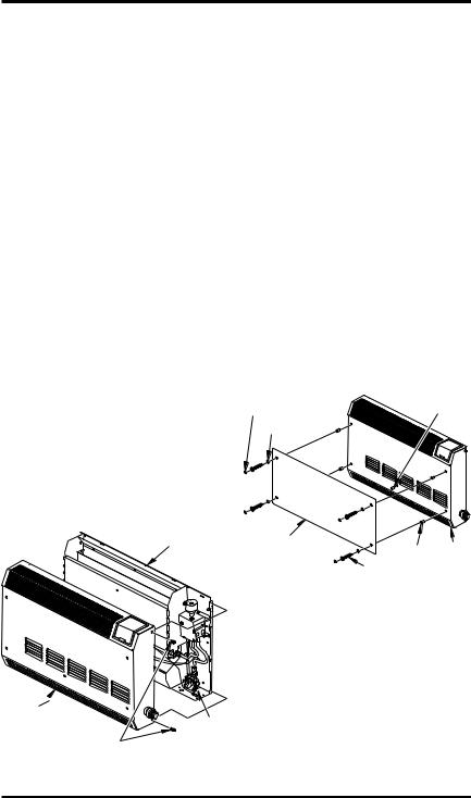
REMOVING FRONT PANEL OF HEATER
1.Removeanddiscardshippingscrewfromback panel of heater (see Figure 4).
2.Remove the four screws, two on each side of front panel. Set aside.
3.Pull front panel forward from the bottom, then lift panel up to remove. If ignitor is installed, pull front panel forward only 2" to 3" (5 to 7.6 cm) away from back panel. Reach into lower right side of heater and disconnect ignitor wire. Set front panel aside.
4.Remove any remaining packaging materials.
Shipping
Screw
Location
Front Panel |
|
Ignitor |
|
|
|
|
Screw |
Wire |
|
|
|
Figure 4 - Removing Front Panel Of Heater |
||
Installing Glass Panel
Items needed from hardware packet:
1 - Bushing
4 - Black spacers
4 - Retaining clips
4 - 1.5" long screws
4 - Screw covers
1.Locate hardware packet and dark acrylic glass.
2.Peel protective coating from both sides of glass.
3.Snap bushing into center front hole of front panel (see Figure 5).
4.Turn front panel face down. Gently press onto a hard surface to snap bushing into hole. Turn panel back over, face up.
5.Place spacers over 4 holes on front panel as shown in Figure 5.
6.Positionglassontopofspacers,aligningholes. Note: If glass gets scratched or marred from normal use, it may be reversed on heater.
7.Place 4 retaining clips on glass over holes.
8.Install screws in each hole, but do not tighten at this time.
9.Square glass up with top front surface of front panel. Tighten screws.
10.Snap screw covers over retaining clips.
Screw Cover |
Bushing |
|
|
Retainer Clip |
|
Glass Panel |
Spacer |
Front |
|
||
|
Screw |
Panel |
|
|
|
Figure 5 - Installing Glass Panel |
||
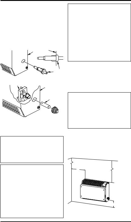
INSTALLING IGNITOR |
|
|
1.Locate ignitor in hardware bag. Determine if your heater is equipped with piezo ignitor or an electronic ignitor (see Figures 6 and 7, page 9.
2.For Piezo Ignitor, snap ignitor into hole located on right side of heater as shown in Figure 6, page 9.
3.For Electronic Ignitor, install ignitor through hole located on right side of heater as shown in Figure 7, page 9.
8 |
www.desatech.com |
116292-01D |
INSTALLATION
Continued
4.For both ignitors, install ignitor wire only when replacing front panel of heater after connecting to gas supply and checking gas connections (see pages 11 through 13). With bottom of front panel only 2" to 3" (5 to 7.6 cm) away from back panel, reach into lower right corner of heater to connect ignitor wire to ignitor terminal (see Figure 4, page 8).
Right Side |
|
of Heater |
|
|
Side View |
|
Piezo |
|
Ignitor |
Figure 6 - Installing Piezo Ignitor |
|
Electronic Ignitor |
Right Side |
|
of Heater |
|
Battery |
Figure 7 - Installing Electronic Ignitor
LOCATING HEATER
This heater is designed to be mounted on a wall.
 WARNING: Maintain the minimum clearances shown in Figure 8. If you can, provide greater clearances from floor, ceiling and joining wall.
 WARNING: Never install the heater
•in a bathroom or a bedroom
•in a recreational vehicle
•wherecurtains,furniture,clothing or other flammable objects arelessthan36"(92cm)fromthe front, top or sides of the heater
•as a fireplace insert
•in high traffic areas
•in windy or drafty areas
 CAUTION: This heater creates warm air currents. These currents move heat to wall surfaces next to heater. Installing heater next to vinyl or cloth wall coverings or operating heater where impurities (such as, but not limited to, tobacco smoke, aromatic candles, cleaning fluids,oilorkerosenelamps,etc.)in the air exist, may discolor walls or cause odors.
IMPORTANT: Vent-free heaters add moisture to the air.Although this is beneficial, installing heater in rooms without enough ventilation air may cause mildew to form from too much moisture. See Air for CombustionandVentilation, page5.Ifhighhumidity is experienced, a dehumidifier may be used to help lower the water vapor content in the air.
 CAUTION: If you install the heater in a home garage
•heater pilot and burner must beatleast18"(45.7cm)above floor
•locate heater where moving vehicle will not hit it
For convenience and efficiency, install heater
•wherethereis easy accessforoperation, inspection and service
•in coldest part of room
Locate heater near a 120V 60Hz electrical outlet (normal household voltage).
|
CEILING |
|
6" (15.2 cm) |
36" |
|
Minimum |
(91.4 cm) |
|
Minimum |
||
From |
||
|
||
Sides Of |
|
|
Heater |
|
|
Left |
Right |
|
Side |
Side |
|
|
Minimum To |
|
|
Top Surface |
|
|
Of Carpeting, |
|
FLOOR |
2" (5.1 cm)Tile Or Other |
|
Combustible |
||
|
Material |
Figure 8 - Mounting Clearances As
Viewed From Front of Heater
116292-01D |
www.desatech.com |
9 |
INSTALLATION
Continued
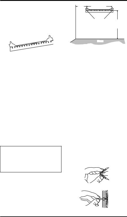
INSTALLING HEATER TO WALL
Mounting Bracket
Locate mounting bracket that has been taped to back panel of heater for shipping. Remove mounting bracket from back panel of heater.
Figure 9 - Mounting Bracket
Methods For Attaching Mounting Bracket To Wall
Only use last hole on each end of mounting bracket toattachbrackettowall.Thesetwoholescentersare 13" (33 cm) apart. Attach mounting bracket to wall in one of two ways:
1.Attaching to wall stud
2.Attaching to wall anchor
Attaching to Wall Stud: This method provides the strongest hold. Insert mounting screws through mounting bracket and into wall studs.
Attaching to WallAnchor: Thismethodallowsyou to attach mounting bracket to hollow walls (wall areas between studs) or to solid walls (concrete or masonry).
Decide which method better suits your needs. Either method will provide a secure hold for the mounting bracket.
Marking Screw Locations
1.Tape mounting bracket to wall where heater will be located. Make sure mounting bracket is level.
 WARNING: Maintain minimumclearancesshowninFigure 10. If you can, provide greater clearances from floor and joining wall.
2.Mark screw locations on wall (see Figure 10).
Note: Only mark last hole on each end of mounting bracket. Insert mounting screws through these holes only.
3.Remove tape and mounting bracket from wall.
Attaching Mounting Bracket To Wall
Note:Wall anchors, mounting screws and spacers are in hardware package. The hardware package is provided with heater.
|
12" |
13" (33 cm) |
|
|
|
(30.4 |
|
|
|
|
cm) |
|
|
|
AdjoiningWall |
Min. |
|
|
|
Only Insert Mounting |
11" |
|||
Screws Through Last |
||||
(27.9 cm) |
||||
|
|
Hole On Each End |
Min. |
|
|
|
|
||
Floor
Figure 10 - Mounting Bracket Clearances
Attaching To Wall Stud Method
For attaching mounting bracket to wall studs
1.Drill holes at marked locations using 9/64" drill bit.
2.Placemounting bracket ontowall. Line up last hole on each end of bracket with holes drilled in wall.
3.Insert mounting screws through bracket and into wall studs.
4.Tighten screws until mounting bracket is firmly fastened to wall studs.
Attaching To Wall Anchor Method
For attaching mounting bracket to hollow walls (wall areas between studs) or solid walls (concrete or masonry)
1.Drill holes at marked locations using 5/16" drillbit.Forsolidwalls(concreteormasonry), drill at least 1" deep.
2.Fold wall anchor as shown in Figure 11.
3.Insert wall anchor (wings first) into hole. Tap anchor flush to wall.
4.For thin walls [1/2" (1.3 cm) or less], insert red keyintowallanchor.Pushredkeyto“pop”open anchor wings. IMPORTANT: Do not hammer key! For thick walls [over 1/2" (1.3 cm) thick] or solid walls, do not pop open wings.
5.Place mounting bracket onto wall. Line up last hole on each end of bracket with wall anchors.
Figure 11 - Folding Anchor
Figure 12 - Popping Open Anchor Wings
For Thin Walls
10 |
www.desatech.com |
116292-01D |
INSTALLATION
Continued
6.Insert mounting screws through bracket and into wall anchors.
7.Tighten screws until mounting bracket is firmly fastened to wall.
Placing Heater On Mounting Bracket
1.Locate two horizontal slots on back panel of heater.
2.Place heater onto mounting bracket. Slide horizontal slots onto stand-out tabs on mounting bracket.
Horizontal Slots
Stand-Out Tab |
Mounting Bracket |
(attached to wall) |
|
Figure 13 - Mounting Heater Onto |
|
Mounting Bracket |
|
Installing Bottom Mounting Screws |
|
1.Locate two bottom mounting holes. These holes are near bottom on back panel of heater (see Figure 14).
2.Mark screw locations on wall.
3.Remove heater from mounting bracket.
4.If installing bottom mounting screws into hollow or solid wall, install wall anchors. Follow steps 1 through 4 under Attaching To Wall Anchor Method, page 10.
If installing bottom mounting screw into wall stud, drill holes at marked locations using 9/64" drill bit.
5.Replace heater onto mounting bracket.
6.Place spacers between bottom mounting holes and wall anchor or drilled hole.
7.Holdspacerinplacewithonehand.Withother hand, insert mounting screw through bottom mounting hole and spacer. Place tip of screw in opening of wall anchor or drilled hole.
8.Tighten both screws until heater is firmly secured to wall. Do not over tighten.
Note: Do not replace front panel at this time. Replace front panel after making gas connec-
tions and checking for leaks.
Front View
Heater
Wall
Spacer
Side View
Figure 14 - Installing Bottom Mounting
Screws
CONNECTING TO GAS SUPPLY
 WARNING: This appliance requires a 3/8" NPT (National PipeThread)inletconnectionto the pressure regulator.
 WARNING:Aqualifiedservice personmustconnectheatertogas supply. Follow all local codes.
 WARNING: For natural gas, never connect heater to private (non-utility) gas wells. This gas is commonly known as wellhead gas.
IMPORTANT: For natural gas, check gas line pressure before connecting heater to gas line. Gas line pressure must be no greater than 10.5" of water. If gas line pressure is higher, heater regulator damage could occur.
 CAUTION: For propane/LP gas, never connect heater directly to the propane/LP supply. This heater requires an external regulator (not supplied). Install theexternalregulatorbetweenthe heater and propane/LP supply.
116292-01D |
www.desatech.com |
11 |
INSTALLATION |
|
Continued |
|
For propane/LP gas, the installer must supply an |
|
external regulator. The external regulator will |
|
reduce incoming gas pressure. You must reduce |
|
incominggaspressuretobetween11and14inches |
|
of water. If you do not reduce incoming gas pres- |
|
sure, heater regulator damage could occur. Install |
|
the external regulator with the vent pointing down |
|
as shown in Figure 15. Pointing the vent down |
|
protects it from freezing rain or sleet. |
|
CAUTION: Use only new, |
|
black iron or steel pipe. Inter- |
|
nally-tinned copper tubing may |
|
be used in certain areas. Check |
|
your local codes. |
Use pipe of |
large enough diameter to allow |
|
proper gas volume to heater. If |
|
pipe is too small, undue loss of |
|
volume will occur. |
|
Typical Inlet Pipe Diameter - 3/8" (9.5 mm) or |
|
greater |
|
Installation must include equipment shutoff valve, |
|
union and plugged 1/8" NPT tap. Locate NPT tap |
|
within reach for test gauge hook up. NPTtap must |
|
be upstream from heater (see Figure 16). |
|
IMPORTANT:Install an equipment shutoff valve |
|
in an accessible location. The equipment shutoff |
|
valve is for turning on or shutting off the gas to |
|
the appliance. |
|
Apply pipe joint sealant lightly to male NPT |
|
threads. This will prevent excess sealant from |
|
going into pipe. Excess sealant in pipe could result |
|
in clogged heater valves. |
|
WARNING: Use pipe joint |
|
sealantthatisresistanttoliquid |
|
petroleum (LP) gas. |
|
Propane/LP |
External |
Supply Tank |
|
|
Regulator |
|
Vent |
|
Pointing |
|
Down |
Figure 15 - External Regulator With Vent |
|
Pointing Down |
|
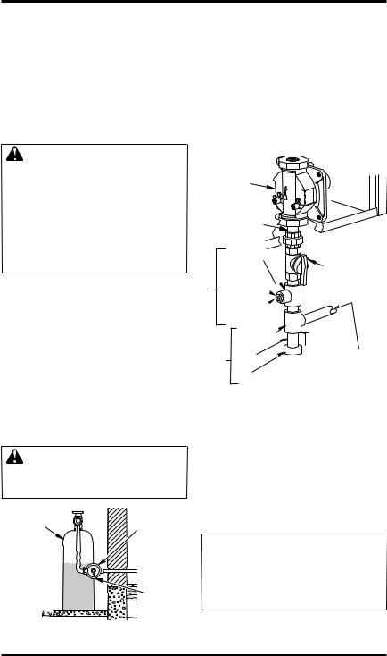
Install sediment trap in supply line as shown in Figure 16. Locate sediment trap where it is within reach for cleaning. Locate sediment trap where trapped matter is not likely to freeze. A sediment trap traps moisture and contaminants. This keeps them from going into heater controls. If sediment trap is not installed or is installed wrong, heater may not run properly.
IMPORTANT: Hold the pressure regulator with wrench when connecting it to gas piping and/or fittings. Do not over tighten pipe connection to regulator. The regulator body could be damaged.
Pressure |
Heater |
Regulator |
|
|
Cabinet |
Test Gauge Connection*
3/8" NPT
Pipe Nipple
Tee Joint
Reducer Bushing to 1/8" NPT 
1/8" NPT 
Plug Tap
Trap |
Tee |
Joint |
|
Pipe |
|||
Sediment |
|||
Nipple |
|||
|
|||
|
Cap |
|
|
Equipment
Shutoff
Valve *
3"
(7.6 cm)

 Min. Natural Gas
From Gas Meter (4" W.C. to 10.5" W.C. Pressure)
Propane/LP
From External Regulator (11" W.C. to 14" W.C.
Pressure)
Figure 16 - Gas Connection
*ACSAdesign-certified equipment shutoff valve with 1/8" NPT tap is an acceptable alternative to test gauge connection. Purchase the optional CSA design-certifiedequipmentshutoffvalvefromyour dealer. See Accessories, page 23.
CHECKING GAS CONNECTIONS
 WARNING:Testallgaspiping and connections, internal and external to unit, for leaks after installing or servicing. Correct all leaks at once.
12 |
www.desatech.com |
116292-01D |
INSTALLATION
Continued
 WARNING:Neveruseanopen flame to check for a leak.Apply a noncorrosive leak detection fluid toalljoints.Bubblesformingshow a leak. Correct all leaks at once.
 CAUTION: For propane/LP gas, make sure external regulator has been installed between propane/LP supply and heater.
See guidelines under Connecting to Gas Supply, page 11.
PRESSURE TESTING GAS SUPPLY PIPING SYSTEM
Test Pressures In Excess Of 1/2 PSIG (3.5 kPa)
1.Disconnect appliance with its appliance main gas valve (control valve) and equipment shutoff valve from gas supply piping system. Pressures in excess of 1/2 psig will damage heater regulator.
2.Cap off open end of gas pipe where equipment shutoff valve was connected.
3.Pressurize supply piping system by either opening propane/LP supply tank valve for propane/LP gas or opening main gas valve located on or near gas meter for natural gas or using compressed air.
4.Check all joints of gas supply piping system. Apply a noncorrosive leak detection fluid to all joints. Bubbles forming show a leak.
5.Correct all leaks at once.
6.Reconnect heater and equipment shutoff valve to gas supply. Check reconnected fittings for leaks.
Test Pressures Equal To or Less Than 1/2 PSIG (3.5 kPa)
1.Close equipment shutoff valve (see Figure 17).
2.Pressurize supply piping system by either opening propane/LP supply tank valve for propane/LP gas or opening main gas valve located on or near gas meter for natural gas or using compressed air.
3.Check all joints from gas meter for natural gas (see Figure 18) or propane/LPsupply tank for propane/LP gas, to equipment shutoff valve (see Figure 19). Apply a noncorrosive leak detection fluid to all joints. Bubbles forming show a leak.
4.Correct all leaks at once.
PRESSURE TESTING HEATER GAS |
||
CONNECTIONS |
|
|
1. |
Open equipment shutoff valve (see Figure 17). |
|
2. |
For natural gas open main gas valve located |
|
|
on or near gas meter. For propane/LPgas open |
|
3. |
propane/LP supply tank valve. |
|
Make sure control knob of heater isinthe OFF |
||
4. |
position. |
|
Check all joints from equipment shutoff valve |
||
|
to thermostat gas valve (see Figure 18 or 19). |
|
|
Apply a noncorrosive leak detection fluid to |
|
5. |
all joints. Bubbles forming show a leak. |
|
Correct all leaks at once. |
|
|
6. |
Light heater (see Operating Heater, page 14). |
|
7. |
Check all other internal joints for leaks. |
|
Turn off heater (see To Turn Off Gas to Appli- |
||
8. |
ance, page 15). |
|
Connect ignitor wire and replace front panel. |
||
Equipment |
Open |
|
Shutoff Valve |
|
|
|
|
Closed |
|
Figure 17 - Equipment Shutoff Valve |
|
|
Gas |
|
|
Meter |
|
|
|
Equipment |
|
|
Shutoff Valve |
Figure 18 - Checking Gas Joints for Natural Gas
Propane/LP
Supply Tank
Equipment
Shutoff Valve
Figure 19 - Checking Gas Joints for Propane/LP Gas
116292-01D |
www.desatech.com |
13 |
INSTALLATION
Continued
CONNECTING TO ELECTRICAL SUPPLY
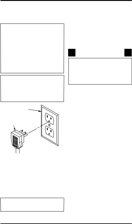
 WARNING: Fan accessory must be grounded. Fan comes with a three-prong, grounding plug as shown in Figure 20. The plug is your protection against electrical shock. Plug it into a standard,three-hole,grounded, outlet. If cord needs replacing, use only a cord with a threeprong, grounding plug.
 CAUTION: Label all wires prior to disconnection when servicingcontrols.Wiringerrors cancauseimproperanddangerous operation (see page 22).
Grounded Outlet
Grounding Plug
Figure 20 - Grounding Plug
EXTENSION CORD
Use extension cord if needed. The cord must have a three-prong, grounding plug and a three-hole receptacle. Make sure cord is in good shape. It must be heavy enough to carry the current needed. An undersized cord will cause a drop in line voltage. This will result in loss of power and overheating. Use a No. 16 AWG cord for lengths less than 50 feet (15.24 m) .
 CAUTION: Verify proper operation after servicing.
Operating Fan Theblowerisconnectedtoathermostat.Whenunit heats up, the fan will operate.Afew minutes after unit cycles off or is turned off, the fan will shut off. The fan will cycle on and off in this manner. Note: If you have a heater with a thermostat, the heater and fan will not turn off and on at exactly the same time. Fan cycle times will vary with the heat setting selected.
OPERATING HEATER
FOR YOUR SAFETY READ
BEFORE LIGHTING
 WARNING: If you do not follow these instructions exactly, a fire or explosion may result causing property damage, personal injury or loss of life.
A.This appliance has a pilot which must be lighted by hand. When lighting the pilot, follow these instructions exactly.
B.BEFORE LIGHTING smell all around the applianceareaforgas.Besuretosmellnext tothefloorbecausesomegasisheavierthan air and will settle on the floor.
WHAT TO DO IFYOU SMELL GAS
•Do not try to light any appliance.
•Do not touch any electric switch; do not use any phone in your building.
•Immediately call your gas supplier from a neighborʼs phone. Follow the gas supplierʼs instructions.
•If you cannot reach your gas supplier, call the fire department.
C.Use only your hand to push in or turn the gas control knob. Never use tools. If the knob will not push in or turn by hand, donʼt try to repairit, call a qualified service technician. Force or attempted repair may result in a fire or explosion.
D.Do not use this appliance if any part has been under water. Immediately call a qualified service technician to inspect the appliance and to replace any part of the control system and any gas control which has been under water.
14 |
www.desatech.com |
116292-01D |
OPERATING HEATER
Continued
LIGHTING
INSTRUCTIONS
1.STOP! Read the safety information, page 14.
2.Make sure equipment shutoff valve is fully open.
3.Turnoffanyelectricpowertotheappliance if service is to be performed.
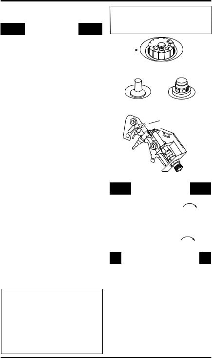
4.Turn control knob clockwise  to the OFF position.
5.Waitfiveminutestoclearoutanygas.Then smellforgas,includingnearthefloor.Ifyou smell gas, STOP! Follow “B” in the safety information,page14.Ifyoudonʼtsmellgas, go to the next step.
6.Turncontrolknobcounterclockwise to the PILOT position. Press in control knob for five (5) seconds.
7.With control knob pressed in, push down and release ignitor button. This will light pilot. The pilot is attached to the front of burner. Note: You may be running this heaterforthe first time afterhooking up to gas supply. If so, you may need to press in control knob for 30 seconds or more. This will allow air to bleed from the gas system. If needed, keep pressing ignitorbutton until pilot lights. If ignitor does not light pilot, refer to Troubleshooting, page 18 orcontact a qualified service person orgas supplier for repairs. Until repairs are made, lightpilotwithmatch.Tolightpilotwithmatch, see Manual Lighting Procedure, page 16.
8.Keepcontrolknobpressedinfor30seconds afterlightingpilot.After30seconds,release control knob.
•If control knob does not pop up when released, contact a qualified service person or gas supplier for repairs.
Note: Ifpilotgoesout,repeatsteps4thru7. Thermostat models have a safety interlock system.Wait one (1) minute before lighting pilot again.
9.Turncontrolknobcounterclockwise to desired heating level. The main burner should light.
 WARNING: Always operate manual control heaters at the locked positions. Operation between these positions may create a possible health hazard if used in a poorly ventilated room. Read owner’s manual for complete instructions.
 CAUTION: Do not try to adjust heating levels by using the equipment shutoff valve.
F
F
O
Figure 21 - Control Knob In The OFF
Position
Piezo Ignitor |
Electronic Ignitor |
|
|
Figure 22 - Ignitor Buttons |
|
Thermocouple

 Ignitor Electrode
 Pilot Burner
Figure 23 - Pilot (actual pilot may vary)
|
TO TURN OFF GAS |
|
|
TO APPLIANCE |
|
Shutting Off Heater |
|
|
1. |
Turn control knob clockwise |
to the |
|
OFF position. |
|
2.Turn off all electric power to the appliance if service is to be performed.
Shutting Off Burner Only (pilot stays lit) |
|
Turn control knob clockwise |
to the |
PILOT position. |
|
THERMOSTAT CONTROL OPERATION
The thermostatic control used on these models differs from standard thermostats. Standard thermostats simply turn on and off the burner. The thermostat used on this heater senses the room temperature. The thermostat adjusts the amountofgasflowtotheburner.Thisincreases or decreases the burner flame height. At times the room may exceed the set temperature. If so, the burner will shut off. The burner will cycle backonwhenroomtemperaturedropsbelowthe set temperature. The control knob can be set to any heat level between 1 and 5. Selecting the 5 setting will cause the burner to remain fully on without modulating down in most cases.
116292-01D |
www.desatech.com |
15 |
OPERATING HEATER
Continued
Note: The thermostat sensing bulb measures the temperature of air near the heater cabinet. This may not always agree with room temperature (depending on housing construction, installation location, room size, open air temperatures,etc.).Frequentuseofyourheaterwill let you determine your own comfort levels.
MANUAL LIGHTING PROCEDURE
1.Remove front panel (see Figure 4, page 8).
2.Follow steps 1 through 7 under Lighting Instructions, page 15.
3.Withcontrolknobpressedin,strikematch. Hold match to pilot until pilot lights.
4.Keepcontrolknobpressedinfor30seconds afterlightingpilot.After30seconds,release control knob. Now follow step 9, under
Lighting Instructions, page 15.
5.Replace front panel.
INSPECTING HEATER
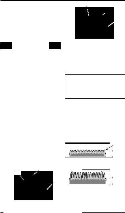
Check pilot flame pattern and burner flame pattern often.
PILOT FLAME PATTERN
Figure 24 shows a correct pilot flame pattern. Figure 25 shows an incorrect pilot flame pattern. The incorrect pilot flame is not touching the thermocouple. This will cause the thermocouple to cool. When the thermocouple cools, the heater will shut down.
If pilot flame pattern is incorrect, as shown in Figure 25
Thermocouple
Yellow Flame
Pilot
 Burner
Figure 25 - Incorrect Pilot Flame Pattern
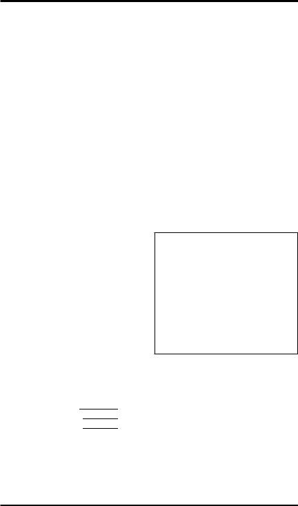
BURNER FLAME PATTERN
 WARNING: If yellow tipping occurs, your heater could produceincreasedlevelsofcarbon monoxide.
NOTICE:Donotmistakeorange flames with yellow tipping. Dirt or other fine particles enter the heater and burn causing brief patches of orange flame.
Figure 26 shows a correct burner flame pattern. Figure 27 shows an incorrect burner flame pattern. The incorrect burner flame pattern shows yellow tipping of the flame. It also shows the flame higher than 1/2 the deflector panel height.
If burner flame pattern is incorrect, as shown in Figure 27
•turn heater off (see To Turn Off Gas To Appliance, page 15)
•see Troubleshooting, page 18
• |
turn heater off (see To Turn Off |
Gas to Appliance, |
Blue |
|
Flame |
||||
|
page 15) |
|
||
|
|
1/2 |
||
• |
see Troubleshooting, page 18 |
|
||
Note: The pilot flame on natural gas units will |
Deflector |
|||
Height |
||||
have a slight curve, but flame should be blue and |
||||
Figure 26 - Correct Burner Flame Pattern |
||||
have no yellow or orange color. |
|
|||
Blue Flame
Thermocouple
Pilot
Burner
Yellow
 Tipping
1 |
/2 |
|
|
Deflector |
|
Height |
|
Figure 27 - Incorrect Burner Flame
Pattern
Figure 24 - Correct Pilot Flame Pattern
16 |
www.desatech.com |
116292-01D |
CLEANING AND
MAINTENANCE
 WARNING: Turn off heater and let cool before cleaning.
 CAUTION: You must keep control areas, burner and circulatingairpassagewaysofheater clean. Inspect these areas of heater before each use. Have heater inspected yearly by a qualifiedserviceperson.Heater may need more frequent cleaning due to excessive lint from carpeting,beddingmaterial,pet hair, etc.
 WARNING: Failure to keep the primary air opening(s) of theburner(s)cleanmayresultin sooting and property damage.
ODS/PILOT AND BURNER
Use a vacuum cleaner, pressurized air or small, soft bristled brush to clean.
BURNER PILOT AIR INLET
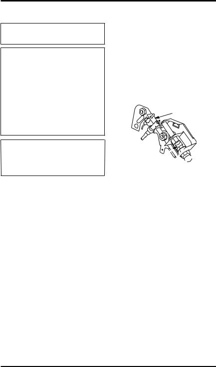
The primary air inlet holes allow the proper amount of air to mix with the gas. This provides a cleanburningflame.Keeptheseholesclearofdust, dirtandlint.Cleantheseairinletholespriortoeach heating season. Blocked air holes will create soot. We recommend that you clean the unit every three monthsduringoperationandhaveheaterinspected yearly by a qualified service person.
We also recommend that you keep the burner tube and pilot assembly clean and free of dust and dirt. To clean these parts we recommend using compressed air no greater than 30 PSI. Your local computer store, hardware store or home center may carry compressed air in a can. You can use a vacuum cleaner in the blow position. If using compressed air in a can, please follow the directions on the can. If you don't follow directions on the can, you could damage the pilot assembly.
1.Shut off the unit, including the pilot. Allow the unit to cool for at least thirty minutes.
2.Inspect burner, pilot for dust and dirt.
3.Blow air through the ports/slots and holes in the burner.
4.Never insert objects into the pilot tube.
Clean the pilot assembly also.Ayellow tip on the pilot flame indicates dust and dirt in the pilot assembly. There is a small pilot air inlet about two inches from where the pilot flame comes out of the pilot assembly (see Figure 28). With the unit off, lightly blow air through the air inlet.You may blow through a drinking straw if compressed air is not available.
Pilot Assembly
Pilot Air Inlet 

Figure 28 - Pilot Inlet Air - Propane/LP Pilot Shown (Actual Pilot May Vary from Illustration)
CABINET
Air Passageways Use a vacuum cleaner or pressurized air to clean.
Exterior and Dark Acrylic Front Glass Use a soft cloth dampened with a mild soap and water mixture. Wipe the cabinet to remove dust.
116292-01D |
www.desatech.com |
17 |
Loading...