


 Loading...
Desa L32, VL36ZNR, VL36EN, VL36EP, VL32HP User Manual
...UNVENTED (VENT-FREE) FIREPLACE
OWNER’S OPERATION AND INSTALLATION MANUAL
MANUALLY CONTROLLED |
REMOTE CONTROL READY |
MODELS |
MODELS |
NATURAL GAS |
NATURAL GAS |
(V)L32(HN, LHN) |
(V)L36(ZNR, LZNR) |
(V)L36(EN, LEN) |
(V)L42(ZNR, LZNR) |
PROPANE/LP GAS |
PROPANE/LP GAS |
(V)L32(HP, LHP) |
(V)L36(ZPR, LZPR) |
(V)L36(EP, LEP) |
(V)L42(ZPR, LZPR) |
WARNING: If the information in this manual is not followed exactly, a fire or explosion may result causing property damage, personal injury or loss of life.
—Do not store or use gasoline or other flammable vapors and liquids in the vicinity of this or any other appliance.
—WHAT TO DO IF YOU SMELL GAS
•Do not try to light any appliance.
•Donottouchanyelectricalswitch;donotuseany phone in your building.
•Immediatelycallyourgassupplierfromaneighbor’s phone. Follow the gas supplier’s instructions.
•If you cannot reach your gas supplier, call the fire department.
—Installationandservicemustbeperformedbyaqualified installer, service agency or the gas supplier.
Save this manual for future reference. For more information, visit www.desatech.com

WARNING: Improper installation, adjustment, alteration, service or maintenance can cause injury or propertydamage.Refertothismanualforcorrectinstallation and operational procedures. For assistance or additional information consult a qualified installer, service agency or the gas supplier.
WARNING: FOR USE ONLY WITH A LISTED DECORATIVE TYPE UNVENTED ROOM HEATER. DO NOT BUILD A WOOD FIRE.
This appliance may be installed in an aftermarket,* permanently located, manufactured (mobile) home, where not prohibited by local codes.
This appliance is only for use with the type of gas indicated on the rating plate. This appliance is not convertible for use with other gases.
*Aftermarket: Completion of sale, not for purpose of resale, from the manufacturer
State of Massachusetts: The installation must be made by a licensed plumber or gas fitter in the Commonwealth of Massachusetts.
Sellers of unvented propane or natural gas-fired supplemental room heaters shall provide to each purchaser a copy of 527 CMR 30 upon sale of the unit.
Vent-free gas products are prohibited for bedroom and bathroom installation in the Commonwealth of Massachusetts.
TABLE OF CONTENTS
Safety Information ............................................... |
3 |
Troubleshooting................................................. |
|
29 |
Local Codes ........................................................ |
4 |
Specifications .................................................... |
|
33 |
Product Features................................................. |
4 |
Wiring Diagram.................................................. |
|
33 |
Locating Firebox.................................................. |
5 |
Service Hints ..................................................... |
|
34 |
Product Specifications......................................... |
5 |
Technical Service .............................................. |
|
34 |
Air For Combustion and Ventilation..................... |
7 |
Replacement Parts............................................ |
|
34 |
Installation ........................................................... |
9 |
Accessories....................................................... |
|
35 |
Operating Fireplace........................................... |
21 |
Illustrated Parts Breakdown and Pars List ........ |
36 |
|
Inspecting Burners ............................................ |
27 |
Warranty Information............................ |
Back Page |
|
Cleaning and Maintenance................................ |
28 |
|
|
|
2 |
www.desatech.com |
115254-01A |

SAFETY INFORMATION
 WARNING:Thisproductcontainsand/orgenerateschemicals known to the state of California to cause cancer or birth defects or other reproductive harm.
IMPORTANT: Read this owner’s manualcarefullyandcompletely before trying to assemble, operate or service this heater.
Improper use of this heater can cause serious injury or death from burns, fire, explosion, electrical shock and carbon monoxide poisoning.
 DANGER: Carbon monoxide poisoning may lead to death!
Carbon Monoxide Poisoning: Early signs of carbon monoxide poisoning resemble the flu, with headaches, dizziness or nausea. If you have these signs, the heater may not be working properly. Get fresh air at once! Have heater serviced. Some people are more affected by carbon monoxide than others.Theseincludepregnantwomen,peoplewith heart or lung disease or anemia, those under the influence of alcohol and those at high altitudes.
Natural and Propane/LP Gas: Natural and propane/LPgases are odorless.An odor-making agent is added to the gas.The odor helps you detect a gas leak. However, the odor added to the gas can fade. Gas may be present even though no odor exists.
Makecertainyoureadandunderstandallwarnings. Keep this manual for reference. It is your guide to safe and proper operation of this heater.
 WARNING: Any change to this heater or its controls can be dangerous.
 WARNING: Do not use a blower insert, heat exchanger insertorotheraccessorynotapproved for use with this heater.
 WARNING: Do not allow fans toblowdirectlyintothefireplace. Avoidanydraftsthatalterburner
flame patterns. Ceiling fans can create drafts that alter burner
flame patterns. Altered burner patterns can cause sooting.
Due to high temperatures, the applianceshouldbelocatedout oftrafficandawayfromfurniture and draperies.
Do not place clothing or other flammable material on or near the appliance. Never place any objects on the heater.
Fireplace front and screen becomeveryhotwhenrunningfireplace. Keep children and adults awayfromhotsurfacestoavoid burns or clothing ignition. Fireplace will remain hot for a time after shutdown. Allow surfaces to cool before touching.
Carefully supervise young children when they are in the room with fireplace. When using the optional hand-held remote accessory, keep selector switch in the OFF position to prevent childrenfromturningonburners with remote.
You must operate this fireplace with the fireplace screen and hood in place. Make sure fireplace screen and hood are in place before running heater.
Keep the appliance area clear and free from combustible materials, gasoline and other flammable vapors and liquids.
115254-01A |
www.desatech.com |
3 |

SAFETY INFORMATION
Continued
1.This appliance is only for use with the type of gasindicatedontheratingplate.Thisappliance is not convertible for use with other gases.
2.Do not place propane/LP supply tank(s) inside any structure. Locate propane/LP supply tank(s) outdoors (propane/LP units only).
3.If you smell gas
•shut off gas supply
•do not try to light any appliance
•do not touch any electrical switch; do not use any phone in your building
•immediately call your gas supplier from a neighborʼs phone. Follow the gas supplierʼs instructions
•if you cannot reach your gas supplier, call the fire department
4.This fireplace shall not be installed in a bedroom or bathroom.
5.Do not use this fireplace as a wood-burning fireplace. Use only the logs provided with the fireplace.
6.Do not add extra logs or ornaments such as pine cones, vermiculite or rock wool. Using these added items can cause sooting. Do not add lava rock around base. Rock and debris could fall into the control area of fireplace.
7.Topreventthecreationofsoot,followtheinstructions in Cleaning and Maintenance, page 28.
8.Before using furniture polish, wax, carpet cleaner or similar products, turn heater off. If heated, the vapors from these products may create a white powder residue within burner box or on adjacent walls or furniture.
9.Thisfireplaceneedsfreshairventilationtorun properly.This fireplace has an Oxygen DepletionSensing(ODS)safetyshutoffsystem.The ODS shuts down the fireplace if enough fresh air is not available. See Air for Combustion and Ventilation, page 7. If fireplace keeps shutting off, see Troubleshooting, page 29.
10.Do not run fireplace
•where flammable liquids or vapors are used or stored
•under dusty conditions
11.Do not use this fireplace to cook food or burn paper or other objects.
12.Donotusefireplaceifanyparthasbeenexposed to or under water. Immediately call a qualified servicetechniciantoinspectthefireplaceandto replace any part of the control system and any gas control which has been under water.
13.Do not operate fireplace if any log is broken. Do not operate fireplace if a log is chipped (dime-sized or larger).
14.Turnfireplaceoffandletcoolbeforeservicing. Only a qualified service person should service and repair fireplace.
15.Operating fireplace above elevations of 4,500 feet could cause pilot outage.
16.Topreventperformanceproblemsinpropane/LP units, do not use propane/LP fuel tanks of less than 100 lbs. capacity (propane/LP units only).
17.Provide adequate clearances around air openings.
LOCAL CODES
Install and use fireplace with care. Follow all local codes. In the absence of local codes, use the latest edition of The National Fuel Gas Code ANSI Z223.1/NFPA 54*.
*Available from:
American National Standards Institute, Inc.
1430 Broadway
New York, NY 10018
National Fire Protection Association, Inc.
Batterymarch Park
Quincy, MA 02269
Note: Where listed vented decorative logs are required, thermostat operation is not permitted.
PRODUCT FEATURES
OPERATION
ThisfireboxisdesignedforusewithapprovedANSI Z21.11.2 decorative type unvented room heaters. (Physical size limitations apply. Refer to minimum firebox requirements supplied with log heater.) It requires no outside venting or chimney making installationeasyandinexpensive.Whenusedwithout the blower, the firebox requires no electricity making it ideal for emergency backup heat.
BLOWER ACCESSORY
The circulating models will accept a rotary type fan (model BK) accessory. The blower circulates heated air from the firebox into the room. Use of blower is optional.
REFRACTORY BRICK LINER
Your firebox may feature a concrete refractory brick liner. As with all concrete liners, this liner may develop slight cracks when exposed to heat. These cracks will not affect the performance of the fireplace or vent-free gas logs.
4 |
www.desatech.com |
115254-01A |
LOCATING FIREBOX
PLANNING
Plan where you will install the firebox. This will savetimeandmoneylaterwhenyouinstallthefirebox. Before installation, consider the following:
1.Where the firebox will be located. Allow for wall and ceiling clearances (see Installation Clearances, page 9).
2.Everything needed to complete installation.
3.These models CANNOT be installed in a bedroom unless the maximum Btu rating of the installed vent-free log set is less than 10,000 Btu/hr.
4.Proper air for combustion and ventilation (page 7).
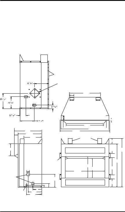
PRODUCT SPECIFICATIONS
32" MODELS
Left Side |
|
View with |
|
Air Kit |
Outside Air |
|
Kit Location |
|
(Optional) |
|
221/2" |
|
4" |
|
Firebox Top View |
|
19 1/2" |
|
2 13/16" |
16 11/16" |
|
|
12 1/4" |
|
8 5/8" |
|
|
|
Right Side |
Built-In |
|
Side |
|
|
View |
|
|
Nailing |
|
|
|
Flanges |
Square |
19/16" |
|
|
|
|
Gas Line |
|
|
Access |
|
81/8" |
Holes |
|
|
|
|
29/16" |
Electrical |
6" 21/4" |
|
Access Hole |
815/16" |
|
|
93/4" |
|


 5/8"
5/8"
251/8"
 291/2"
  347/16"
363/8"
Standoffs
41/4"
361/2"
|
31/2" |
|
321/4" |
187/16" |
1415/16" |
163/4" |
|
291/2" |
|
|
33/8" |
65/16"
Front View
Figure 1 - Firebox Dimensions (32" Models)
115254-01A |
www.desatech.com |
5 |

PRODUCT SPECIFICATIONS
Continued
36" AND 42" MODELS
Note: If only one dimension is shown, the dimension is the same for both 36" and 42" models.
Firebox Top View
Left Side |
Outside Air |
|
View with |
||
Kit Location |
||
Air Kit |
||
(Optional) |
||
|
Right
Side
View
Front View
Figure 2 - Firebox Dimensions (36" and 42" Models)
6 |
www.desatech.com |
115254-01A |

AIR FOR COMBUSTION AND VENTILATION
 WARNING:Thisfireboxshall not be installed in a confined space or unusually tight construction unless provisions are provided for adequate combustionandventilationair.Readthe following instructions to insure proper fresh air for this and other fuel-burning appliances in your home.
Todayʼs homes are built more energy efficient than ever. New materials, increased insulation and new construction methods help reduce heat loss in homes. Home owners weather strip and caulk around windows and doors to keep the cold air out and the warm air in. During heating months, home owners want their homes as airtight as possible.
While it is good to make your home energy efficient, your home needs to breathe. Fresh air must enter your home.All fuel-burning appliances need fresh air for proper combustion and ventilation.
Exhaust fans, fireboxes, clothes dryers and fuel burning appliances draw air from the house to operate. You must provide adequate fresh air for these appliances. This will insure proper venting of vented fuel-burning appliances.
PROVIDING ADEQUATE VENTILATION
ThefollowingareexcerptsfromNational Fuel Gas Code, ANSI Z223.1/NFPA 54, Section 5.3, Air for Combustion and Ventilation.
All spaces in homes fall into one of the three following ventilation classifications:
1.Unusually Tight Construction
2.Unconfined Space
3.Confined Space
The information on page 7 through 9 will help you classify your space and provide adequate ventilation.
Unusually Tight Construction
The air that leaks around doors and windows may provide enough fresh air for combustion and ventilation. However, in buildings of unusually tight construction, you must provide additional fresh air.
Unusually tight construction is defined as construction where:
a.walls and ceilings exposed to the outside atmosphere have a continuous water vapor retarder with a rating of one perm (6 x 10-11 kg per pa-sec-m2) or less with openings gasketed or sealed and
b.weather stripping has been added on openable windows and doors and
c.caulking or sealants are applied to areas such as joints around window and door frames, between sole plates and floors, between wall-ceiling joints, between wall panels, at penetrations for plumbing, electrical and gas lines and at other openings.
If your home meets all of the three criteria above, you must provide additional fresh air. See Ventilation Air From Outdoors, page 9.
If your home does not meet all of the three criteria above, proceed to Determining Fresh-Air Flow for Firebox Location.
Confined and Unconfined Space
The National Fuel Gas Code, ANSI Z223.1/NFPA 54 defines a confined space as a space whose volume is less than 50 cubic feet per 1,000 Btu per hour (4.8 m3 per kw) of the aggregate input rating of all appliances installed in that space and an unconfined space as a space whose volume is not less than 50 cubic feet per 1,000 Btu per hour (4.8 m3 per kw) of the aggregate input rating of all appliances installed in that space. Rooms communicating directly with the space in which the appliances are installed*, through openings not furnished with doors, are considered a part of the unconfined space.
* Adjoining rooms are communicating only if therearedoorlesspassagewaysorventilationgrills between them.
DETERMINING FRESH-AIR FLOW FOR HEATER LOCATION
Determining if You Have a Confined or Unconfined Space
Use this work sheet to determine if you have a confined or unconfined space.
Space: Includes the room in which you will install heater plus any adjoining rooms with doorless passageways or ventilation grills between the rooms.
115254-01A |
www.desatech.com |
7 |
AIR FOR COMBUSTION AND VENTILATION
Continued
1.Determine the volume of the space (length x width x height).
Length x Width x Height =________ cu. ft. (volume of space)
Example: Space size 22 ft. (length) x 18 ft. (width) x 8 ft. (ceiling height) = 3168 cu. ft. (volume of space)
If additional ventilation to adjoining room is suppliedwithgrillsoropenings,addthevolume of these rooms to the total volume of the space.
2.Multiply the space volume by 20 to determine the maximum Btu/Hr the space can support.
_______(volumeofspace)x20=(Maximum Btu/Hr the space can support)
Example: 3168 cu. ft. (volume of space) x 20 = 63,360(maximumBtu/Hrthespacecansupport)
3.Add the Btu/Hr of all fuel burning appliances in the space.
Vent-free heater |
__________ Btu/Hr |
|
Gas water heater* |
__________ Btu/Hr |
|
Gas furnace |
__________ Btu/Hr |
|
Vented gas heater |
__________ |
Btu/Hr |
Gas fireplace logs |
__________ |
Btu/Hr |
Other gas appliances* + |
________ |
Btu/Hr |
|
Total |
= |
________ |
Btu/Hr |
* Do not include direct-vent gas appliances. Direct-vent draws combustion air from the outdoors and vents to the outdoors.
Example: |
40,000 |
|
Gas water heater |
|
|
__________ Btu/Hr |
||
Vent-free heater |
39,000 |
Btu/Hr |
+ ________ |
||
Total |
79,000 |
Btu/Hr |
= ________ |
||
4.Compare the maximum Btu/Hr the space can support with the actual amount of Btu/Hr used.
__________Btu/Hr (maximum the space can support)
__________Btu/Hr (actual amount of Btu/Hr used)
Example: 63,360 Btu/Hr (maximum the space can support)
79,000 Btu/Hr (actual amount of Btu/Hr used)
The space in the above example is a confined space because the actual Btu/Hr used is more than the maximum Btu/Hr the space can support. You must provide additional fresh air. Your options are as follows:
A.Rework worksheet, adding the space of an adjoining room. If the extra space provides an unconfined space, remove door to adjoining room or add ventilation grills between rooms. See Ventilation Air From Inside Building.
B.Vent room directly to the outdoors. See Ventilation Air From Outdoors, page 9.
C.Install a lower Btu/Hr heater, if lower Btu/Hr size makes room unconfined.
If the actual Btu/Hr used is less than the maximum Btu/Hr the space can support, the space is an unconfined space. You will need no additional fresh air ventilation.
 WARNING:Iftheareainwhich the heater may be operated is smaller than that defined as an unconfinedspaceorifthebuilding is of unusually tight construction, provideadequatecombustionand ventilationairbyoneofthemethods describedintheNational Fuel Gas Code,ANSIZ223.1/NFPA54Section 5.3 or applicable local codes.
VENTILATION AIR
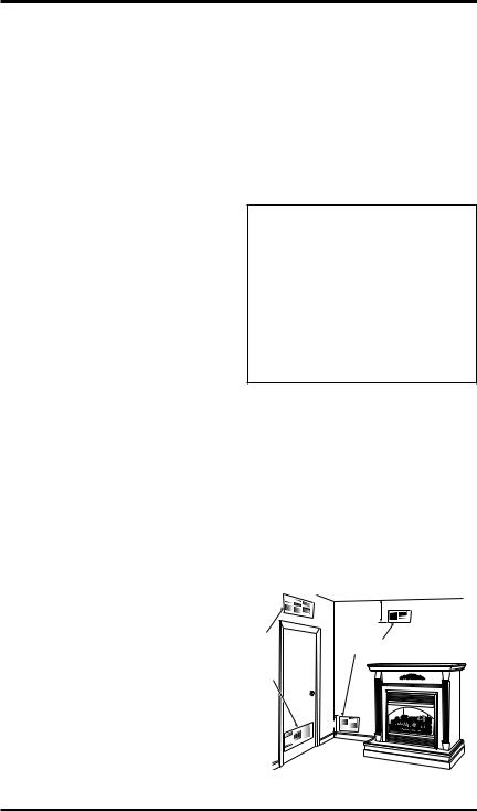
Ventilation Air From Inside Building
This fresh air would come from an adjoining unconfined space. When ventilating to an adjoining unconfined space, you must provide two permanent openings: one within 12" of the ceiling and one within 12" of the floor on the wall connecting the two spaces (see options 1 and 2, Figure 4).You can also remove door into adjoining room (see option 3, Figure 3). Follow the National Fuel Gas Code, ANSI Z223.1/NFPA 54, Section 5.3, Air for Combustion and Ventilation for required size of ventilation grills or ducts.
|
|
12" |
|
Ventilation |
|
Ventilation Grills |
|
Grills |
|
||
Into |
Or |
Into Adjoining Room, |
|
Adjoining |
Option 2 |
||
Remove |
|||
Room, |
|
||
Door into |
|
||
Option 1 |
|
||
Adjoining |
|
||
|
|
||
|
Room, |
|
|
|
Option |
|
|
|
3 |
|
|
|
|
12" |
Figure 3 - Ventilation Air from Inside Building
8 |
www.desatech.com |
115254-01A |
AIR FOR COMBUSTION
AND VENTILATION
Continued
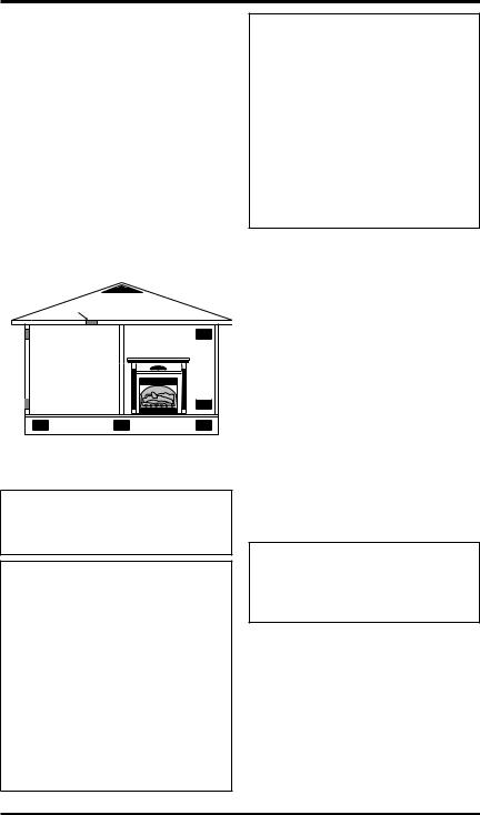
Ventilation Air From Outdoors
Provideextrafreshairbyusingventilationgrillsor ducts.You must provide two permanent openings: one within 12" of the ceiling and one within 12" of the floor. Connect these items directly to the outdoors or spaces open to the outdoors. These spaces include attics and crawl spaces. Follow the
National Fuel Gas Code, ANSI Z223.1/NFPA 54, Section 5.3,Air for Combustion and Ventilation for required size of ventilation grills or ducts.
IMPORTANT: Do not provide openings for inlet or outlet air into attic if attic has a thermostatcontrolledpowervent. Heated airentering the attic will activate the power vent.
|
Outlet |
Ventilated |
|
Attic |
|
|
Air |
|
|
|
|
Outlet |
|
|
Air |
|
To Attic |
|
|
|
|
|
To |
|
|
Crawl |
Inlet |
|
Space |
|
|
|
Air |
|
|
|
Inlet Air |
Ventilated |
|
Crawl Space |
|
|
|
Figure 4 - Ventilation Air from Outdoors
INSTALLATION
 WARNING: A qualified servicepersonmustinstallfirebox. Follow all local codes.
 WARNING: Never install the firebox
•in a bedroom or bathroom*
•in a recreational vehicle
•where curtains, furniture, clothing or other flammable objectsarelessthan42inches from the front, top or sides of the firebox
•in high traffic areas
•in windy or drafty areas
*Unless the installed log set is rated at 10,000 Btu/Hr or less.
 CAUTION: Log heaters installedinthisfireboxcreatewarm aircurrents.Thesecurrentsmove heat to wall surfaces next to firebox.Installingfireboxnexttovinyl orclothwallcoveringsoroperatingfireboxwhereimpurities(such as, but not limited to, tobacco smoke, aromatic candles, cleaning fluids, oil or kerosene lamps, etc.) in the air exist, may discolor walls or cause odors.
IMPORTANT:Vent-freegaslog heaters addmoisture to the air.Although this is beneficial, installing fireboxinroomswithoutenoughventilationairmay causemildewtoformfromtoomuchmoisture.See
Air for Combustion and Ventilation, page 7.
IMPORTANT: Make sure the firebox is level. If firebox is not level, log set will not work properly.
Note:Your firebox is designed to be used in zero clearance installations. Wall or framing material can be placed against any exterior surface on the rear, sides, top or bottom of your firebox, except where standoff spacers are integrally attached. If standoff spacers are attached to your firebox, these spacerscanbeplaceddirectlyagainstwallorframingmaterials.Usethedimensionsshownforrough opening to create the easiest installation.
Use dimensions shown for rough openings to create the easiest installation (see Built-In Firebox Installation, page 11).
INSTALLATION CLEARANCES
 WARNING: Maintain the minimum clearances. If you can, provide greater clearances from
floor, ceiling and adjoining wall.
Carefully follow these instructions. This will ensure safe installation.
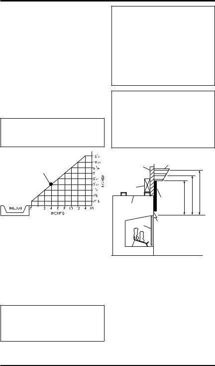
Minimum Wall and Ceiling Clearances (see Figure 5, page 10)
A.Clearances from the side of the fireplace cabinet to any combustible material and wall should follow diagram in Figure 5, page 10.
Example: The face of a mantel, bookshelf, etc. is made of combustible material and protrudes 3 1/2" from the wall. This combustible material must be 4" from the side of the fireplace cabinet (see Figure 5, page 10).
115254-01A |
www.desatech.com |
9 |
INSTALLATION
Continued
B.Clearancesfromthetopofthefireboxopeningto the ceiling should not be less than 42 inches.
C.When the firebox is installed on carpeting or other combustible material, other than wood flooring, the firebox should be installed on a metal or wood panel extending the full width and depth of the enclosure.
D.Clearances from the bottom of firebox to the floor is 0 inches.
These fireboxes can be installed as freestanding units against a wall with the approved, optional cabinet mantels (see Accessories, page 35) or as a built-in unit.The clearances are the same for either installation method.
 CAUTION: Do not install the firebox directly on carpet or vinyl.
NOTICE: Surface temperatures ofadjacentwallsandmantelsbecomehotduringoperation.Walls and mantels above the firebox may become hot to the touch.
If installed properly, these temperatures meet the requirement ofthenationalproductstandard. Follow all minimum clearances shown in this manual.
NOTICE: If your installation does notmeettheminimumclearances shown, you must do one of the following:
•raise the mantel to an acceptable height
•remove the mantel
Example |
* |
*Minimum 16 inches from Side Wall
Figure 5 - Minimum Clearance for Combustible to Wall
Mantel Clearances for Built-In Installation
If placing custom mantel above built-in firebox, you must meet the minimum allowable clearance between mantel shelf and top of firebox opening shown in Figure 6. These are the minimum allowable mantel clearances for a safe installation. Use larger clearances wherever possible to minimize the heating of objects and materials placed on the mantel.
 CAUTION: Do not allow the vent-free gas log heater to touch or extend beyond the fireplace screen.
Wall board or facing material (above firebox) may be of combustible material, including decorative mantel ornaments or other similar projections off of the facing material.
Framing
Material
Firebox
Wire-mesh
Screen
Mantel Shelf
Note: Any portion of the mantel shelf must NOT
extend beyond this profile.
12"
63/4"
11/2"
Noncombustible Material May
Project Off this 12" 16" 20" Surface above
the Firebox Hood
|
Note: All vertical |
|
Supplied Firebox |
measurements are |
|
from top of fireplace |
||
Hood Must Be |
||
hood opening to |
||
Used at All Times |
||
bottom of mantel shelf. |
||
|
||
|
These minimum |
|
|
clearances replace any |
|
|
other recommended |
|
|
clearances supplied with |
|
|
your ANSI Z21.11.2 |
|
|
approved gas logs. |
Figure 6 - Minimum Mantel Clearances
for Built-In Installation
BUILT-IN FIREBOX INSTALLATION
Built-in installationof thisfireboxinvolvesinstalling firebox into a framed-in enclosure.This makes the front of firebox flush with wall. Optional brass trim accessories are available (see Accessories, page 35). The brass trim will extend past sides of firebox approximately 1/2 inch. This will cover the rough edges of the wall opening. If installing a mantel above the firebox, you must follow the clearancesshowninFigure6.Followtheseinstructions to install the firebox in this manner.
10 |
www.desatech.com |
115254-01A |
INSTALLATION
Continued
1.Frame in rough opening. The firebox framing should be constructed of 2 x 4 lumber or heavier. Use dimensions in Table 1 and rough opening layout in Figure 7a.Adjust framing so thatfireboxflusheswithfinishedwallsurface.If installinginacorner,usedimensionsinFigures 7b, 7c and 7d for rough opening.
2.Install gas piping to firebox location (see
Connecting to Gas Supply, page 16.) IMPORTANT: If installing blower accessory (circulating models with louvers only), see
Hard-Wiring Firebox, page 15.
3.Carefully set firebox in front of rough opening with back of firebox inside wall opening. IMPORTANT: If installing a perimeter trim kit, seeinstructionsincludedwithtrimaccessory.You must install shoulder screws from trim kit now.
4.Carefully insert firebox into rough opening.
5.Attach firebox to wall studs using nails or wood screws through holes in nailing flange (see Figure 8).
6.If using an optional perimeter trim kit, install the trim after final finishing and/or painting of wall. See instructions included with trim accessory for attaching trim.
7.Install and properly test gas log heater. Follow installationinstructionsincludedwiththeventfree gas log heater that is being installed.
IMPORTANT:Whenfinishingyourfirebox,combustiblematerialssuchaswallboard,gypsumboard,sheet rock,drywall,plywood,etc.maybebuttedupnextto thesidesandtopofthefirebox.Combustiblematerials should never overlap the firebox front facing.
 WARNING: Do not allow any combustiblematerialstooverlap the firebox front facing.
IMPORTANT: Noncombustible materials such as brick, tile, etc. may overlap the front facing, but should never cover any necessary openings like louvered slots.
Table 1
Rough Opening Dimensions for
Built-in Installation
|
Front Width |
|
Depth |
Model |
(Inside to Inside) |
Height |
(Min.) |
|
|
|
|
32" |
34 7/8" |
36 3/4" |
16 1/4" |
36" |
41 1/2" |
40 1/2" |
20 3/4" |
42" |
48 5/8" |
44 1/2" |
22 5/8" |
 WARNING: Do not allow noncombustible materials to cover any necessary openings like louvered slots.
 WARNING: Use only noncombustible mortar or adhesiveswhenoverlappingthefront facing with noncombustible facing material.
|
|
|
Depth |
Figure 7a |
|
|
|
(Minimum) |
|
|
Height |
|
||
|
|
|
Width |
|
|
|
|
(InsidetoInside) |
|
|
|
|
|
FOR 32" |
|
|
|
" |
MODELS |
|
|
16 |
|
|
|
|
7/ |
|
|
30" |
42 |
|
|
Figure 7b |
|
|
|
|
|
|
|
|
347/8" |
|
|
|
|
60" |
|
|
|
|
TOP VIEW |
|
|
|
|
|
FOR 36" |
|
|
|
" |
MODELS |
|
|
/32 |
|
|
|
|
11 |
|
|
37" |
2 |
|
|
|
5 |
|
|
Figure 7c |
|
|
|
|
|
|
|
|
|
411/2" |
|
|
|
|
74" |
|
|
|
|
TOP VIEW |
|
|
|
|
|
FOR 42" |
|
|
|
" |
MODELS |
|
|
|
6 |
|
|
|
/1 |
|
|
|
|
13 |
|
|
43" |
0 |
|
|
|
6 |
|
|
Figure 7d |
|
|
|
|
|
|
485/8" 

86" TOP VIEW
Figure 7 - Rough Opening for Installing in Wall
Nails or Wood
Screws
Nailing
Flanges
Figure 8 - Attaching Firebox to Wall Studs
115254-01A |
www.desatech.com |
11 |

INSTALLATION
Continued
INSTALLING FIREBOX USING OPTIONAL ACCESSORY MANTELS
 WARNING: A qualified servicepersonmustinstallfirebox. Follow all local codes.
This firebox may be installed using a cabinet mantel accessory against a wall in your home. The firebox and cabinet mantel can be installed directly on the floor. A trim kit is included with the mantel accessories.
1.Assemble cabinet mantel accessory and the trim kit. Assembly instructions are included with each accessory.
2.Ifusinganoptionalbloweraccessory(circulating models only), install a properly grounded, 120voltthree-prongelectricaloutletatfirebox location if an outlet is not there. If possible, locate outlet so cabinet mantel will cover it when installed (see Figure 9).
3.Install gas piping to firebox location. See
Connecting to Gas Supply, page 15. You may have to cut an access hole in the floor or wall to run gas line to firebox. Make sure to locate access hole so cabinet mantel will cover it when installed (see Figure 9).
4.Place cabinet mantel on floor in desired location. Make sure mantel is flush against wall.
5.Breakoffnailingflangeswithhammerorpliers (32" models only, see Figure 10).
Cabinet
Mantel 
Electrical
Outlet
Gas Line Access Hole |
Gas Piping |
(Either Side of Firebox) |
|
Figure 9 - Installing Cabinet Mantel
6.Installthetrimkitfurnishedwithmantel.Seeinstruction sheet included with the mantel now.
7.If installing an optional blower accessory (circulating models only), see Installing Optional Blower Accessories, page 13.
8.Carefullyinsertfireboxintocabinetmantel.Be careful not to scratch firebox, cabinet mantel, flooring, etc. when installing (see Figure 11).
9.Install and properly test gas log heater. Follow installationinstructionsincludedwiththeventfree gas log heater that is being installed.
Nailing
 Flanges
Figure 10 - Location of Nailing Flanges (Two on Each Side), 32" Model Shown (Model May Vary From Illustration)
Figure 11 - Inserting Firebox Into
Cabinet Mantel (Model May Vary From
Illustration)
12 |
www.desatech.com |
115254-01A |
INSTALLATION
Continued
INSTALLING OPTIONAL BLOWER ACCESSORIES
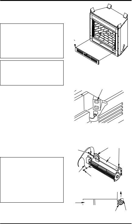
NOTICE: The firebox identificationlabel(includingmodelnumber, serial number, clearances, etc.) is located in the right side screen pocket area on the front of the firebox. See Figure 25, page 15.
NOTICE: If a log set is installed in the firebox, disconnect log setfromgassupplyandremove fromfirebox.Contactaqualified service person to do this.
Note:Appearance of firebox may vary depending on model.
The blower accessory option for use in the ventfree fireboxes is model BK. Model BK is a rotary squirrel cage type blower with magnetic attachment and variable speed control.
The blower is installed by removing the lower face panel.To remove the lower face panel, pull the left andright latchestowardthe center of the appliance until they are disengaged from their locator holes (see Figure 12).
Models with louvered front panels can also be removed by inserting fingertips between slots and gently pulling out. DO NOT FORCE. The panels are actually held in place by means of a retention dimple embossed on the edge of removable panels.
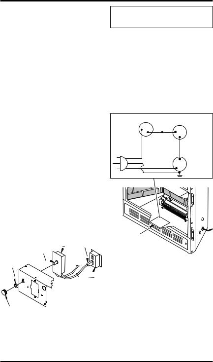
 WARNING:Ifthereisaduplex electrical outlet installed in the right side of the bottom of the
fireplace base area (see Figure 13), be sure that the electrical power to the outlet is turned off before proceeding with blower installation. Failure to do this may result in serious injury.
1.Attach the power cord to the blower motor by firmly pushing the two female terminals at the end of the power cord onto the two spade terminals on the blower motor (see Figure 14).
Lower
Louver
Panel
Figure 12 - Accessing Blower
Compartment (Controls Not Shown
for Clarity)
Duplex Electrical Outlet
Figure 13 - Accessing Duplex Electrical |
|||
Outlet Installed in Bottom Right Side of |
|||
|
Firebox |
|
|
Spade |
Magnetic Strips |
||
Exhaust |
|
||
Terminals |
|
||
Port |
|
||
|
|
||
Green |
|
|
|
Ground |
|
|
|
Wire |
Screw |
|
|
|
Air Flow |
||
|
Direction |
||
Blower |
Side View |
|
|
Firebox Bottom |
|
||
Installed |
|
||
|
|
||
After |
|
|
|
Lower |
|
|
|
Panel |
Blower |
Magnets |
|
Removed |
|||
Location |
|||
|
|
||
Figure 14 - Blower Model BK |
|||
115254-01A |
www.desatech.com |
13 |
INSTALLATION
Continued
2.Attach green ground wire from power cord to blower housing using screw provided (see Figure 14, page 13). Tighten screws securely with a phillips screwdriver.
3.Place the blower against the lower rear wall of thefireboxouterwrapperwiththeexhaustport directed upward. Depending on your model, you may have to carefully route the blower assembly past the controls and brackets and position the blower inside the back opening. The blower will be held in position against the back wall by the magnets incorporated onto the blower housing (see Figure 14, page 13).
4.Becertainthatallwireterminalsaresecurelyattachedtoterminalsonblowermotorandthatthe screw retaining the green ground wire is tight.
5.Mount speed control box by placing plastic control shaft through bottom hole on speed control bracket. Top screw head on control box will fit insidetopholeonbracket(seeFigure15).Secure speedcontroltobracketwithlocknutbypushing and turning lock nut with pliers clockwise until it is tight against bracket.
6.Place control knob, provided, onto control shaft (see Figure 15).
7.Check to make sure power cord is completely clear of blower wheel and there are no foreign objects in blower wheel. Also, double check all wire leads and make sure wire routing is not pinched or in a precarious position. Correct accordingly.
|
Speed |
Blower |
|
Control |
Plug-In |
Control |
|
|
Shaft |
|
|
Locknut |
|
|
|
Duplex Outlet |
|
|
(Located under |
|
|
firebox floor |
|
Control Knob |
against lower |
|
right outside wall) |
||
Figure 15 - Attaching Speed Control to Firebox with Panel Louvers
 CAUTION: Never touch the blower wheel while in operation.
8.Turn on power to duplex outlet if previously turned off per warning on page 13.
9.Plug in blower power cord to duplex outlet (see Figure 15, page 13).
10.Turn blower on and check for operation. Turn bloweroffbyturningknobfullycounterclockwise before continuing.
11.Peeloffbackingpaperandsticksuppliedwiring diagramdecalonfireboxbottomapproximately 12" in from of blower (see Figure 16).
12.Replace all panels and/or brick bottom panel if previously removed.
|
|
Variable |
|
Fan Switch |
|
Fan Switch |
|||
|
|
|
|
(N.O.) |
|
Off |
1 |
Black |
|
|
2 |
|
||
|
|
|
||
|
|
On |
Blue |
|
|
|
|
||
|
|
|
|
Red |
110/115 |
|
|
|
(BKT Model |
|
|
|
Only) |
|
V.A.C. |
Black |
|
|
|
|
|
|
||
|
|
|
|
|
|
Green |
|
|
Blower |
|
White |
|
|
Motor |
Wiring Diagram
Decal 12" in
Front of Blower
Figure 16 - Location of Wiring Diagram Decal (Model May Vary From Illustration)
14 |
www.desatech.com |
115254-01A |
Loading...