


 Loading...
VENT-FREE COMPACT FIREPLACE
OWNER’S OPERATION AND INSTALLATION MANUAL
Shown with Optional
Cabinet Mantel/Hearth
Base Accessory
HDCFTP, HDCFTN, CGCFTP AND CGCFTN
14,000 to 26,000 Btu/Hr with Thermostat
WARNING: If the information in this manual is not followed exactly, a fire or explosion may result causing property damage, personal injury or loss of life.
—Do not store or use gasoline or other flammable vapors and liquids in the vicinity of this or any other appliance.
—WHAT TO DO IF YOU SMELL GAS
•Do not try to light any appliance.
•Donottouchanyelectricalswitch;donotuseany phone in your building.
•Immediatelycallyourgassupplierfromaneighbor’s phone. Follow the gas supplier’s instructions.
•If you cannot reach your gas supplier, call the fire department.
—Installationandservicemustbeperformedbyaqualified installer, service agency or the gas supplier.
Save this manual for future reference. For more information, visit www.desatech.com

WARNING: Improper installation, adjustment, alteration, service or maintenance can cause injury or propertydamage.Refertothismanualforcorrectinstallation and operational procedures. For assistance or additional information consult a qualified installer, service agency or the gas supplier.
WARNING: This is an unvented gas-fired heater. It uses air (oxygen) from the room in which it is installed. Provisions for adequate combustion and ventilation air must beprovided.RefertoAir for Combustion and Ventilation section on page 6 of this manual.
This appliance may be installed in an aftermarket,* permanently located, manufactured (mobile) home, where not prohibited by local codes.
This appliance is only for use with the type of gas indicated on the rating plate. This appliance is not convertible for use with other gases.
*Aftermarket: Completion of sale, not for purpose of resale, from the manufacturer
State of Massachusetts: The installation must be made by a licensed plumber or gas fitter in the Commonwealth of Massachusetts.
Sellers of unvented propane or natural gas-fired supplemental room heaters shall provide to each purchaser a copy of 527 CMR 30 upon sale of the unit.
Vent-free gas products are prohibited for bedroom and bathroom installation in the Commonwealth of Massachusetts.
TABLE OF CONTENTS
Safety Information ............................................... |
3 |
Cleaning and Maintenance |
................................ |
22 |
Local Codes ........................................................ |
4 |
Troubleshooting................................................. |
|
23 |
Product Information............................................. |
4 |
Specifications .................................................... |
|
27 |
Product Features................................................. |
5 |
Replacement Parts............................................ |
|
27 |
Unpacking ........................................................... |
5 |
Service Hints ..................................................... |
|
27 |
Assembly............................................................. |
5 |
Technical Service .............................................. |
|
27 |
Air For Combustion and Ventilation..................... |
6 |
Illustrated Parts Breakdown .......and Parts List |
28 |
|
Installation ........................................................... |
8 |
Accessories....................................................... |
|
30 |
Operating Fireplace........................................... |
19 |
Parts Centrals.................................................... |
|
31 |
Inspecting Burner .............................................. |
21 |
Warranty Information............................ |
Back Page |
|
2 |
www.desatech.com |
111044-01F |

SAFETY INFORMATION
 WARNING:Thisproductcontainsand/orgenerateschemicals known to the state of California to cause cancer or birth defects or other reproductive harm.
IMPORTANT: Read this owner’s manualcarefullyandcompletely before trying to assemble, operate or service this fireplace.
Improper use of this fireplace can cause serious injury or death from burns, fire, explosion,electricalshockandcarbon monoxide poisoning.
 DANGER:Carbonmonoxide
poisoning may lead to death!
CarbonMonoxidePoisoning:Earlysignsofcarbon monoxide poisoning resemble the flu, with headaches, dizziness or nausea. If you have these signs, the heater may not be working properly. Get fresh airat once! Have fireplace serviced. Some people are more affected by carbon monoxide than others. These include pregnant women, people with heart orlungdiseaseoranemia,thoseundertheinfluence of alcohol and those at high altitudes.
Natural and Propane/LP Gas: Natural and pro- pane/LPgasesareodorless.Anodor-makingagent isaddedto the gas.Theodorhelps youdetecta gas leak. However, the odor added to the gas can fade. Gas may be present even though no odor exists.
Makecertainyoureadandunderstandallwarnings. Keep this manual for reference. It is your guide to safe and proper operation of this fireplace.
 WARNING: Any change to this fireplace or its controls can be dangerous.
 WARNING:Donotallowfans toblowdirectlyintothefireplace. Avoidanydraftsthatalterburner flame patterns. Ceiling fans can create drafts that alter burner flame patterns. Altered burner patterns can cause sooting.
 WARNING:Donotuseablower insert, heat exchanger insert orotheraccessorynotapproved for use with this fireplace.
Due to high temperatures, the applianceshouldbelocatedout oftrafficandawayfromfurniture and draperies.
Do not place clothing or other
flammable material on or near the appliance. Never place any objects on the heater.
Fireplace front and screen becomes very hot when running fireplace. Keep children and adultsawayfromhotsurfacesto avoidburnsorclothingignition. Fireplace will remain hot for a time after shutdown. Allow surfaces to cool before touching.
Carefully supervise young children when they are in the room with fireplace.
You must operate this fireplace with the fireplace screen in place. Make sure fireplace screen is closed before running
fireplace.
Keep the appliance area clear and free from combustible materials, gasoline and other flammable vapors and liquids.
111044-01F |
www.desatech.com |
3 |
SAFETY INFORMATION
Continued
1.This appliance is only for use with the type of gasindicatedontheratingplate.Thisappliance is not convertible for use with other gases.
2.Do not place propane/LP supply tank(s) inside anystructure.Locatepropane/LPsupplytank(s) outdoors (propane/LP units only).
3.If you smell gas
•shut off gas supply
•do not try to light any appliance
•donottouchanyelectricalswitch;donotuse any phone in your building
•immediately call your gas supplier from a neighborʼs phone. Follow the gas supplierʼs instructions
•if you cannot reach your gas supplier, call the fire department
4.This fireplace shall not be installed in a bedroom or bathroom.
5.Do not use this fireplace as a wood-burning fireplace. Use only the logs provided with the fireplace.
6.Do not add extra logs or ornaments such as pine cones, vermiculite or rock wool. Using these added items can cause sooting. Do not add lava rock around base. Rock and debris could fall into the control area of fireplace.
7.This fireplace is designed to be smokeless. If logs ever appear to smoke, turn off fireplace and call a qualified service person. Note: During initial operation, slight smoking could occur due to log curing and fireplace burning manufacturing residues.
8.To prevent the creation of soot, follow the instructions in Cleaning and Maintenance, page 22.
9.Before using furniture polish, wax, carpet cleaner or similar products, turn heater off. If heated, the vapors from these products may create a white powder residue within burner box or on adjacent walls or furniture.
10.Thisfireplaceneedsfreshairventilationtorun properly.This fireplace has an Oxygen DepletionSensing(ODS)safetyshutoffsystem.The ODS shuts down the fireplace if not enough fresh air is available. See Air for Combustion and Ventilation, page 6. If fireplace keeps shutting off, see Troubleshooting, page 23.
11.Do not run fireplace
•where flammable liquids or vapors are used or stored.
•under dusty conditions.
12.Do not use this fireplace to cook food or burn paper or other objects.
13.Never place any objects in the fireplace or on logs.
14.Do not use fireplace if any part has been under water. Immediately call a qualified service technician to inspect the room fireplace and to replace any part of the control system and any gas control which has been under water.
15.Turn off and unplug fireplace and let cool before servicing. Only a qualified service person should service and repair fireplace.
16.Operating fireplace above elevations of 4,500 feet could cause pilot outage.
17.Do not operate fireplace if any log is broken. Do not operate fireplace if a log is chipped (dime-sized or larger).
18.To prevent performance problems, do not use propane/LP fuel tank of less than 100 lbs. capacity (propane/LP units only).
19.Provide adequate clearances around air openings.
LOCAL CODES
Install and use fireplace with care. Follow all local codes. In the absence of local codes, use the latest edition of The National Fuel Gas Code ANSI Z223.1/NFPA 54*.
*Available from:
American National Standards Institute, Inc.
1430 Broadway
New York, NY 10018
National Fire Protection Association, Inc.
Batterymarch Park
Quincy, MA 02269
PRODUCT INFORMATION
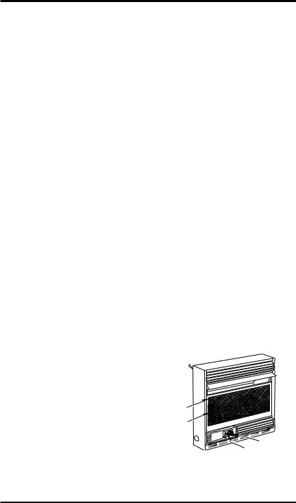
Fireplace
Cabinet
Screen
Log Set
Control |
Knob
Ignitor
Button
Figure 1 - Vent-Free Gas Compact
Fireplace
4 |
www.desatech.com |
111044-01F |
PRODUCT FEATURES
SAFETY PILOT
This fireplace has a pilot with an Oxygen Depletion Sensing (ODS) safety shutoff system. The ODS/pilot is a required feature for vent-free room fireplaces.The ODS/pilot shuts off the fireplace if there is not enough fresh air.
PIEZO IGNITION SYSTEM
This fireplace has a piezo ignitor. This system requires no matches, batteries or other sources to light fireplace.
THERMOSTATIC HEAT CONTROL
This fireplace has a thermostat sensing bulb and a control valve. The thermostat will automatically modulate the heat output to maintain a consistent room temperature.This results in greater fireplace comfort. This can also result in lower gas bills.
UNPACKING
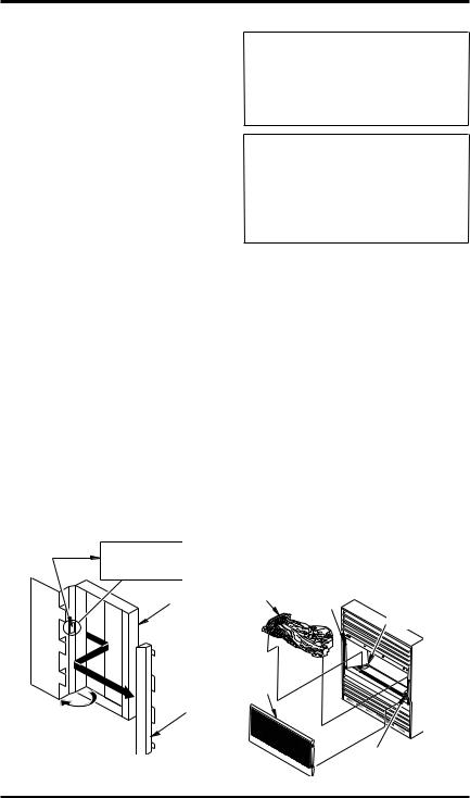
1.Remove log box and fireplace from carton. IMPORTANT: The fireplace hood is inside the cardboard protective end wrap on the left side of fireplace (as viewed from front). A decal is on the outside of the cardboard end wrap stating hood is enclosed (see Figure 2).
2.Remove hood from cardboard protective end wrap as shown in Figure 2.
3.Remove all protective packaging applied to fireplace for shipment.
4.Make sure your fireplace includes one hardware packet.
5.Check fireplace for any shipping damage. If fireplace is damaged, promptly inform dealer where you bought fireplace.
Hood |
|
IMPORTANT: |
Enclosed |
|
THIS PACKAGE CONTAINS A |
|
FIREPLACE HOOD. UNWRAP |
|
Decal |
|
CARTON AND REMOVE HOOD |
|
BEFORE DISCARDING |
|
|
|
PROTECTIVE PACKAGING. |
|
|
Cardboard |
|
|
Protective |
|
|
Fireplace |
|
|
End Wrap |
|
|
2 |
|
1 |
Hood |
|
|
Figure 2 - Removing Fireplace Hood
ASSEMBLY
 WARNING: Always have branch support and screen in placebeforeoperatingfireplace. Thispreventsexcessivetemperatures on fireplace surfaces.
 WARNING:Failuretoposition thepartsinaccordancewiththese diagrams or failure to use only parts specifically approved with this fireplace may result in property damage or personal injury.
ASSEMBLING FIREPLACE |
|||
Tools Required: |
|
|
|
• |
Phillips screwdriver |
• |
slotted screwdriver |
• |
5/16" hex wrench |
• |
scissors |
Installing Log |
|
|
|
1.Lift screen up and pull out to remove.
2.Cut two plastic straps to remove the log from the firebox cavity.
3.An optional blower is available for models CGCFTP and CGCFTN. See Accessories, page 30. Install optional blower now. Follow installation instructions provided with blower.
4.Remove log packaging material and discard packaging. Gently place log set on burner support (see Figure 3). The log should fit flat against top of burner support and log locator tabs fit into the slots under the log. Do not allow log to contact flame. If flame contacts log, soot will be created.
5.Reattach screen by placing the notches in the screen frame over the shoulder screws and pushing down.
Log |
Shoulder |
Burner Support |
|
Screw |
with Log |
|
|
Locator Tabs |
Screen |
|
|
|
|
Branch |
|
|
Support |
Figure 3 - Assembling Fireplace |
||
111044-01F |
www.desatech.com |
5 |
ASSEMBLY
Continued
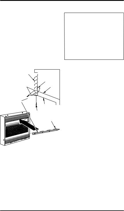
Assembling Hood
1.Locate four black phillips sheet metal screws from the hardware packet.
2.Rotate hood as shown in Figure 4. Make sure hood tabs point toward fireplace.
3.Insert hood tabs between baffle and louvers (see Figure 4).
4.Gently rotate hood to upright position. Make sure hood tabs are behind louvers and hood is resting on firebox top (see Figure 4).
5.Align screw holes on hood with screw holes on firebox top.
6.Insert screws as shown in Figure 4. Tighten screws firmly.
Louver
Hood Tab
Baffle
Hood
Firebox
Top
Sheet
Metal Hood
Screws Tabs
Figure 4 - Assembling Hood
AIR FOR COMBUSTION AND VENTILATION
 WARNING: This heater shall not be installed in a confined space or unusually tight construction unless provisions are provided for adequate combustionandventilationair.Readthe following instructions to insure proper fresh air for this and other fuel-burning appliances in your home.
Todayʼs homes are built more energy efficient than ever. New materials, increased insulation and new construction methods help reduce heat loss in homes.Homeownersweatherstripandcaulkaround windows and doors to keep the cold air out and the warm air in. During heating months, home owners want their homes as airtight as possible.
While it is good to make your home energy efficient, your home needs to breathe. Fresh air must enter your home.All fuel-burning appliances need fresh air for proper combustion and ventilation.
Exhaust fans, fireplaces, clothes dryers and fuel burning appliances draw air from the house to operate. You must provide adequate fresh air for these appliances. This will insure proper venting of vented fuel-burning appliances.
PROVIDING ADEQUATE VENTILATION
ThefollowingareexcerptsfromNational Fuel Gas Code, ANSI Z223.1/NFPA 54, Section 5.3, Air for Combustion and Ventilation.
All spaces in homes fall into one of the three following ventilation classifications:
1.Unusually Tight Construction
2.Unconfined Space
3.Confined Space
The information on pages 6 through 8 will help you classify your space and provide adequate ventilation.
Unusually Tight Construction The air that leaks around doors and windows may provide enough fresh air for combustion and ventilation. However, in buildings of unusually tight construction, you must provide additional fresh air.
6 |
www.desatech.com |
111044-01F |

AIR FOR COMBUSTION
AND VENTILATION
Continued
Unusually tight construction is defined as construction where:
a.walls and ceilings exposed to the outside atmosphere have a continuous water vapor retarder with a rating of one perm (6 x 10-11 kg per pa-sec-m2) or less with openings gasketed or sealed and
b.weather stripping has been added on openable windows and doors and
c.caulking or sealants are applied to areas such as joints around window and door frames, between sole plates and floors, between wall-ceiling joints, between wall panels, at penetrations for plumbing, electrical and gas lines and at other openings.
If your home meets all of the three criteria above,youmustprovideadditionalfreshair. See Ventilation Air From Outdoors, page 8.
If your home does not meet all of the three criteria above, proceed to Determining Fresh-Air Flow For Fireplace Location.
Confined and Unconfined Space
The National Fuel Gas Code, ANSI Z223.1/NFPA 54 defines a confined space as a space whose volumeislessthan50cubicfeetper1,000Btuperhour (4.8 m3 per kw) of the aggregate input rating of all appliancesinstalledinthatspaceandanunconfined space as a space whose volume is not less than 50 cubicfeetper1,000Btuperhour(4.8m3perkw)of theaggregateinputratingofallappliancesinstalled in that space. Rooms communicating directly with the space in which the appliances are installed*, through openings not furnished with doors, are considered a part of the unconfined space.
* Adjoining rooms are communicating only if therearedoorlesspassagewaysorventilationgrills between them.
DETERMINING FRESH-AIR FLOW FOR HEATER LOCATION
Determining if You Have a Confined or Unconfined Space
Use this work sheet to determine if you have a confined or unconfined space.
Space: Includes the room in which you will install heater plus any adjoining rooms with doorless passageways or ventilation grills between the rooms.
1.Determine the volume of the space (length x width x height).
Length x Width x Height =__________cu. ft. (volume of space)
Example: Space size 20 ft. (length) x 16 ft. (width) x 8 ft. (ceiling height) = 2560 cu. ft. (volume of space)
If additional ventilation to adjoining room is supplied with grills or openings, add the volume of these rooms to the total volume of the space.
2.Multiply the space volume by 20 to determine the maximum Btu/Hr the space can support.
__________ (volume of space) x 20 = (Maximum Btu/Hr the space can support)
Example: 2560 cu. ft. (volume of space) x 20 = 51,200 (maximum Btu/Hr the space can support)
3.Add the Btu/Hr of all fuel burning appliances in the space.
Vent-free heater |
___________ Btu/Hr |
Gas water heater* |
___________ Btu/Hr |
Gas furnace |
___________ Btu/Hr |
Vented gas heater |
___________ Btu/Hr |
Gas fireplace logs |
___________ Btu/Hr |
Other gas appliances* +___________ |
Btu/Hr |
|
Total |
=___________ |
Btu/Hr |
* Do not include direct-vent gas appliances. Di- rect-ventdrawscombustionairfromtheoutdoors and vents to the outdoors.
Example:
Gas water heater |
30,000 |
|
__________ Btu/Hr |
||
Vent-free heater |
26,000 |
|
+ ________ Btu/Hr |
||
Total |
= 56,000 |
Btu/Hr |
4.Compare the maximum Btu/Hr the space can support with the actual amount of Btu/Hr used.
_________Btu/Hr(maximumthespacecansupport)
_________Btu/Hr (actual amount of Btu/Hr used)
Example: 51,200 Btu/Hr (maximum the space can support)
56,000 Btu/Hr (actual amount of Btu/Hr used)
The space in the above example is a confined space because the actual Btu/Hr used is more than the maximum Btu/Hr the space can support.You must provide additional fresh air. Your options are as follows:
A.Reworkworksheet,addingthespaceofanadjoiningroom.Iftheextraspaceprovidesanunconfined space, remove door to adjoining room or add ventilation grills between rooms. See Ventilation Air From Inside Building, page 8.
B.Vent room directly to the outdoors. See Ventilation Air From Outdoors, page 8.
C.Install a lower Btu/Hr fireplace, if lower Btu/Hr size makes room unconfined.
111044-01F |
www.desatech.com |
7 |
AIR FOR COMBUSTION
AND VENTILATION
Continued
If the actual Btu/Hr used is less than the maximum Btu/Hr the space can support, the space is an unconfined space. You will need no additional
 WARNING: If the area in which the heater may be operatedissmallerthanthatdefined as an unconfined space or if the building is of unusually tight construction, provide adequate combustion and ventilation air byoneofthemethodsdescribed in the National Fuel Gas Code, ANSIZ223.1/NFPA54Section5.3 or applicable local codes.
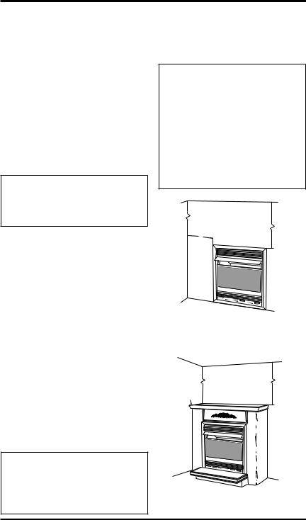
VENTILATION AIR
Ventilation Air From Inside Building
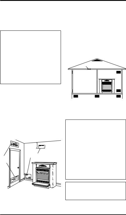
This fresh air would come from an adjoining unconfined space. When ventilating to an adjoining unconfined space, you must provide two permanent openings: one within 12" of the ceiling and one within 12" of the floor on the wall connecting the two spaces (see options 1 and 2, Figure 5).You can also remove door into adjoining room (see option 3, Figure 5). Follow the National Fuel Gas Code, ANSI Z223.1/NFPA 54, Section 5.3, Air for Combustion and Ventilation for required size of ventilation grills or ducts.
|
12" |
|
Ventilation Grills |
Ventilation |
Into Adjoining Room, |
Option 2 |
|
Grills |
Or |
into Adjoining |
Remove |
Room, |
Door into |
Option 1 |
Adjoining |
|
Room, |
|
Option 3 |
|
12" |
Figure 5 - Ventilation Air from Inside Building Shown with Optional Mantel
Ventilation Air From Outdoors
Provideextrafreshairbyusingventilationgrillsor ducts.You must provide two permanent openings: one within 12" of the ceiling and one within 12" of the floor. Connect these items directly to the outdoors or spaces open to the outdoors. These spaces include attics and crawl spaces. Follow the
National Fuel Gas Code, ANSI Z223.1/NFPA 54, Section 5.3,Air for Combustion and Ventilation for required size of ventilation grills or ducts.
IMPORTANT: Do not provide openings for inlet or outlet air into attic if attic has a thermostatcontrolledpowervent.Heatedairenteringtheattic will activate the power vent.
|
Outlet |
Ventilated |
|
Attic |
|
|
Air |
|
|
|
|
Outlet |
|
|
Air |
|
To Attic |
|
|
|
|
|
To |
|
|
Crawl |
Inlet |
|
Space |
|
|
|
Air |
|
|
|
Inlet Air |
Ventilated |
|
Crawl Space |
|
|
|
Figure 6 - Ventilation Air from Outdoors Shown with Optional Mantel
INSTALLATION
NOTICE:Thisheaterisintended for use as supplemental heat.
Use this heater along with your primary heating system. Do not install this heater as your primary heat source. If you have a centralheatingsystem,youmay run system’s circulating blower whileusingheater.Thiswillhelp circulatetheheatthroughoutthe house. In the event of a power outage, you can use this heater as your primary heat source.
 WARNING: A qualified service person must install fireplace. Follow all local codes.
8 |
www.desatech.com |
111044-01F |
INSTALLATION
Continued
Note: Your fireplace is designed to be used in zero clearance installations. Wall or framing material can be placed directly against any exterior surface of your fireplace, except where standoff spacers are integrally attached. If standoff spacers are attached toyourfireplace,thesespacerscanbeplaceddirectly against wall or framing materials.
Use the dimensions shown for rough openings to create the easiest installation (see Built-In Fireplace Installation, page 10).
CHECK GAS TYPE
Use the correct gas type (natural or propane/LP) for your unit. If your gas supply is not correct, do not install fireplace. Call dealer where you bought fireplace for proper type fireplace.
 WARNING: This appliance is equipped for (natural or propane/LP) gas. Field conversion is not permitted.
INSTALLATION ITEMS
Before installing fireplace, make sure you have the items listed below.
•external regulator - propane/LP only (supplied by installer)
•piping (check local codes)
•sealant (resistant to propane/LP gas)
•equipment shutoff valve *
•test gauge connection *
•ground joint union
•sediment trap
•tee joint
•pipe wrench
* A CSA design-certified equipment shutoff valve with 1/8" NPT tap is an acceptable alternative to test gauge connection. Purchase the optional CSA design-certifiedequipmentshutoffvalvefromyour dealer. See Accessories, page 30.
Note:Ifdesired,purchaseafour-sidedbrasstrimkit for built-in installations. See Accessories, page 30.
LOCATING FIREPLACE
 WARNING: Maintain the minimum clearances shown in Figures 7 and 8. If you can, providegreaterclearancesfrom floor, ceiling and joining wall.
You can recess firebox into the wall. You can also position fireplace in the optional cabinet or corner mantels. IMPORTANT: Only use optional cabinet or corner mantels specified in this manual. Purchasetheoptionalmantelfromyourdealer(see
Accessories, page 30).
 WARNING: Never install the fireplace
•in a bedroom or a bathroom
•in a recreational vehicle
•wherecurtains,furniture,clothing or other flammable objects are lessthan36inchesfromthefront, top or sides of the fireplace
•as a fireplace insert
•in high traffic areas
•in windy or drafty areas
CEILING
|
36" Minimum |
6" |
|
Minimum |
|
From |
|
Sides Of |
|
Fireplace |
|
Left |
Right |
Side |
Side |
FLOOR
Figure 7 - Mounting Clearances As
Viewed From Front of Fireplace Shown
Built In The Wall
CEILING
36" Top Of Minimum Mantel Can
Be Flush
With Wall
Right
Left Side
Side
Figure 8 - Mounting Clearances As
Viewed From Front of Fireplace Shown
with Optional Mantel
111044-01F |
www.desatech.com |
9 |
INSTALLATION
Continued
 CAUTION:Thisfireplacecreates warm air currents. These currents move heat to wall surfacesnexttofireplace.Installing fireplace next to vinyl or cloth wall coverings or operating
fireplacewhereimpurities(such as, but not limited to, tobacco smoke,aromaticcandles,cleaningfluids,oilorkerosenelamps, etc.)intheairexist,maydiscolor walls or cause odors.
IMPORTANT: Vent-free fireplaces add moisture totheair.Althoughthisisbeneficial,installingfireplace in rooms without enough ventilation air may causemildewtoformfromtoomuchmoisture.See
Air for Combustion and Ventilation, page 6.
Note:Wheninstallingfireplacedirectlyoncarpeting, tile or other combustible material, other than wood flooring, the fireplace shall be installed on a metal or wood panel extending the full width and depth of the fireplace.
 CAUTION: If you install the fireplace in a home garage
•fireplacepilotandburnermust be at least 18 inches above
floor.
•locatefireplacewheremoving vehicle will not hit it.
Forconvenienceandefficiency,installfireplace
•where there is easy access for operation, inspection and service.
•in coldest part of room
An optional blower kit is available from your dealer.SeeAccessories,page30.Ifplanningtouse blower, locate fireplace near an electrical outlet.
BUILT-IN FIREPLACE INSTALLATION
Built-in installation of this fireplace involves installing fireplace into a framed-in enclosure. This makes the front of fireplace flush with wall. An optional brass trim kit accessory is available (see Accessories, page 30). Brass trim will extend pastsidesoffireplaceapproximately1/2inch.This will cover the rough edges of the wall opening. If installingabuilt-inmantelabovethefireplace,you must follow the clearances shown in Figure 12, page 12. Follow the instructions below to install thefireplaceinthismanner.Note:Yourfireplaceis designed to be used in zero clearance installations. Wall or framing material can be placed directly against any exterior surface on the rear, sides or top of your fireplace.
|
Actual |
Framing |
Height |
26" |
26 7/8" |
Front Width |
26 3/4" |
26 7/8" |
Depth |
9 1/2" |
10 1/2" |
Bottom |
3/4" |
3/4" |
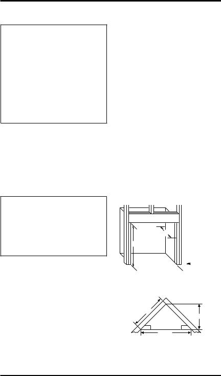
1.Frame in rough opening. Use dimensions shown in Figure 9 for the rough opening.
Ifinstallinginacorner,usedimensionsshown in Figure10 forthe rough opening.The height is267/8"whichisthesameasthewallopening above.
10 1/2"
267/8"
3/4" Off

 The Floor
 267/8"
 Minimum
Figure 9 - Rough Opening for Installing in Wall
365/8"
257/8"
 267/8"
  513/4"
Figure 10 - Rough Opening for Installing in Corner
10 |
www.desatech.com |
111044-01F |
Loading...