


®
VENTED PROPANE
GAS HEATERS
OWNER’S OPERATION AND INSTALLATION MANUAL
Models: GVR65BPA, GVR65PA, GVR50BPA, GVR50PA, GVR35PA
WARNING: If the information in this manual is not followed exactly, a fire or explosion may result causing property damage, personal injury, or loss of life.
FOR YOUR SAFETY
—Do not store or use gasoline or other flammable vapors and liquids in the vicinity of this or any other appliance.
—WHAT TO DO IF YOU SMELL GAS
•Do not try to light any appliance.
•Do not touch any electrical switch; do not use any phone in your building.
•Immediately call your gas supplier from a neighbor’s phone. Follow the gas supplier’s instructions.
•If you cannot reach your gas supplier, call the fire department.
—Installation and service must be performed by a qualified installer, service agency, or the gas supplier.
WARNING: Improper installation, adjustment, alteration, service, or maintenance can cause property damage, personal injury or loss of life. Refer to this manual for correct installation and operational procedures. For assistance or additional information consult a qualified installer, service agency, or the gas supplier.
®
Save this manual for future reference.

CONTENTS |
SECTION |
PAGE |
|
Safety Information ......................................................................... |
3 |
|
Product Identification .................................................................... |
5 |
|
Local Codes ................................................................................... |
6 |
|
Unpacking .................................................................................... |
6 |
|
Product Features ............................................................................ |
6 |
|
Installing Heater ............................................................................ |
6 |
|
Check Gas Type ...................................................................... |
6 |
|
Installation Items ..................................................................... |
6 |
|
Locating Heater ....................................................................... |
7 |
|
Venting Heater ........................................................................ |
8 |
|
Connecting to Gas Supply ...................................................... |
11 |
|
Checking Gas Connections ..................................................... |
13 |
|
Installing Radiants .................................................................. |
14 |
|
Installing Glass Panel ............................................................. |
15 |
|
Air For Combustion and Ventilation ............................................. |
17 |
|
Determining Fresh-Air Flow for Heater Location |
|
|
Example 1: Locating Heater in Unconfined (Open) Area 18 |
|
|
Draft Hood Spillage Test ............................................ |
18 |
|
Providing Permanent Fresh-Air Ventilation .............. |
19 |
|
Example 2: Locating Heater in Confined (Closed) Area .. |
20 |
|
Ventilating Confined Area ......................................... |
20 |
|
Operating Heater ........................................................................... |
21 |
|
For Your Safety Read Before Lighting .................................. |
21 |
|
Lighting Instructions ............................................................... |
21 |
|
Manual Lighting Procedure .................................................... |
23 |
|
Blower Operation (For Models with Blower) ........................ |
23 |
|
To Turn Off Gas To Appliance .............................................. |
23 |
|
Inspecting Pilot and Burner Flame ................................................ |
24 |
|
Pilot Flame Pattern .................................................................. |
24 |
|
Burner Flame Pattern .............................................................. |
24 |
|
Cleaning and Maintenance ............................................................ |
26 |
|
Troubleshooting ............................................................................. |
27 |
|
Service Procedures ........................................................................ |
32 |
|
Removing Control Valve and Burner Tube ............................ |
32 |
|
Removing Burner .................................................................... |
33 |
|
Changing Burner Orifice ........................................................ |
34 |
|
Blower Wiring Diagram ................................................................ |
34 |
|
Technical Service .......................................................................... |
35 |
|
Specifications ................................................................................ |
35 |
|
Service Hints ................................................................................. |
35 |
|
Ordering Replacement Parts .......................................................... |
36 |
|
Parts Centrals ................................................................................. |
36 |
|
Accessories .................................................................................... |
37 |
|
Illustrated Parts List ...................................................................... |
38-41 |
|
Warranty Information .................................................................... |
Back Cover |
2
100791
SAFETY |
|
|
|
|
|
|
|
|
|
|
|
|
|
|
|
|
|
|
|
|
|
|
WARNING ICON G 001 WARNINGS |
|
|
|
|||
INFORMATION |
|
|
IMPORTANT: Read this owner’s manual carefully and completely before |
|
|
||||
|
|
trying to assemble, operate, or service this heater. Improper use of this |
|
|
|||||
|
|
|
|
|
|||||
|
|
|
heater can cause serious injury or death from burns, fire, explosion, |
|
|
||||
|
|
|
electrical shock, and carbon monoxide poisoning. |
|
|
|
|||
|
|
|
|
|
|
|
|
|
|
|
|
|
|
DANGER |
|
|
|
|
|
|
|
|
|
Carbon monoxide poisoning may lead to death! |
|
|
|
|
|
|
|
|
|
|
|
|
|
||
|
|
|
Carbon Monoxide Poisoning: Early signs of carbon monoxide poisoning |
|
|
||||
|
|
|
resemble the flu, with headaches, dizziness, or nausea. If you have these signs, the |
|
|
||||
|
|
|
heater may not be operating or venting properly. Get fresh air at once! Have heater |
|
|
||||
|
|
|
or heater venting system serviced. Some people are more affected by carbon |
|
|
||||
|
|
|
monoxide than others. These include pregnant women, people with heart or lung |
|
|
||||
|
|
|
disease or anemia, those under the influence of alcohol, and those at high altitudes. |
|
|
||||
|
|
|
Propane Gas: Propane gas is odorless. An odor-making agent is added to propane |
|
|
||||
|
|
|
gas. The odor helps you detect a propane gas leak. However, the odor added to |
|
|
||||
|
|
|
propane gas can fade. Propane gas may be present even though no odor exists. |
|
|
|
|||
|
|
|
Make certain you read and understand all Warnings. Keep this manual for reference. |
|
|
||||
|
|
|
It is your guide to safe and proper operation of this heater. |
|
|
|
|||
|
|
|
1. A qualified service person must install heater and venting system. |
|
|
|
|||
|
|
|
2. Use only propane gas. Do not convert heater to use different fuel type. |
|
|
|
|||
|
|
|
3. Do not place propane supply tank(s) inside any structure. Locate propane supply |
|
|
||||
|
|
|
tank(s) outdoors. |
|
|
|
|||
|
|
|
4. If you smell gas |
|
|
|
|||
|
|
|
• Shut off gas supply. |
|
|
|
|||
|
|
|
• Do not try to light any appliance. |
|
|
|
|||
|
|
|
• Do not touch any electrical switch; do not use any phone in your building. |
|
|
|
|||
|
|
|
• Immediately call your gas supplier from a neighbor’s phone. Follow the gas |
|
|
||||
|
|
|
supplier’s instructions. |
|
|
|
|||
|
|
|
• If you cannot reach your gas supplier, call the fire department. |
|
|
|
|||
|
|
|
5. This heater must have fresh air for proper operation. If not, poor fuel combustion |
|
|
||||
|
|
|
and improper venting of flue gases will result. Carbon monoxide poisoning from |
|
|
||||
|
|
|
backed-up flue gases could occur. The State of California lists carbon monoxide |
|
|
||||
|
|
|
as a reproductive toxin under Proposition 65. Read the instructions under Air for |
|
|
||||
|
|
|
Combustion and Ventilation, pages 17 through 20 for complete information. |
|
|
|
|||
|
|
|
6. Never install the heater |
|
|
|
|||
|
|
|
• in a mobile home or a recreational vehicle. |
|
|
|
|||
|
|
|
• where curtains, furniture, clothing, or other flammable objects are less than 48 |
|
|
|
|||
|
|
|
inches from the front, 53 inches from top, or 12 inches from right side and 6 |
|
|
|
|||
|
|
|
inches from left side and back of heater. |
|
|
|
|||
|
|
|
• directly on carpeting, tile, or other combustible materials other than wood |
|
|
||||
|
|
|
flooring. Place heater on metal or wood panel extending the full width and |
|
|
||||
|
|
|
depth of heater. |
|
|
|
|||
|
|
|
• as a fireplace insert. |
|
|
|
|||
|
|
|
• in high traffic areas. |
|
|
|
|||
|
|
|
• in windy or drafty areas. |
|
|
|
|||
|
|
|
|
|
|
|
|
|
|
|
|
|
|
Continued |
|
3 |
|
||
|
|
|
|||||||
|
|
|
|
|
|
|
|
|
|
100791
SAFETY INFORMATION
Continued
WARNINGS Continued
WARNING ICON |
G 001 |
7.Provide the following minimum heater clearances from combustibles (as viewed from the front of heater):
Front: 48 inches
Back: 6 inches
Top: 53 inches
Right Side: 12 inches
Left Side: 6 inches
8.Do not run heater
•where flammable liquids or vapors are used or stored
•under dusty conditions
9.Never place clothing or any flammable objects on the heater or venting system.
10.Heater and venting system surfaces are very hot during operation. Keep children and adults away from hot surfaces to avoid burns or clothing ignition. Carefully supervise young children when they are in the same room as heater. Heater will remain hot for a time after shutdown. Let surface cool before touching.
11.Do not use heater as a cooking device.
12.Do not alter heater or its controls. Any change may create a safety hazard.
13.Turn off heater and unplug (if equipped with blower) and let cool before servicing. Unless you need gas supply for testing, shut off manual shutoff valve before servicing. Only a qualified service person should service and repair heater and venting system.
14.Replace any safety screen or guard removed for servicing before running heater.
15.Do not use heater if any part has been under water. Immediately call a qualified service person to inspect the heater and to replace any part of the control system and any gas control which has been underwater.
4
100791

PRODUCT |
Control |
Blower Switch |
|
(on models |
|||
IDENTIFICATION |
|||
Knob |
equipped with |
||
|
|
blower) |
Ignitor
Button
Burner
Radiants
Lower Front
Access Panel
Figure 1 - Vented Propane Gas Heater, Radiant Front
Draft Hood
Outlet for
Venting
System
Control
Valve
Blower (on models
equipped with blower)
Figure 2 - Vented Propane Gas Heater, Rear View
5
100791

|
LOCAL CODES |
|
Install and use heater with care. Follow all local codes. In the absence of local |
||||||
|
|
||||||||
|
|
codes, use the latest edition of the following: |
|||||||
|
|
|
|
||||||
|
|
|
|
|
|
• National Fuel Gas Code ANSI Z223.1, also known as NFPA 54 * |
|||
|
|
|
|
|
|
• National Electrical Code ANSI/NFPA 70 * |
|||
|
|
|
|
|
|
• National Standard of Canada CAN1-B149 ** |
|||
|
|
|
|
*Available from: American National Standards Institute, Inc., 1430 Broadway, |
|||||
|
|
|
|
New York, NY 10018; National Fire Protection Association, Inc., Batterymarch |
|||||
|
|
|
|
Park, Quincy, MA 02269. |
|
|
|
||
|
|
|
|
**Available from: Standards Council of Canada, 350 Sparks Street, Ottawa, |
|||||
|
|
|
|
Ontario K1R 7S8. |
|
|
|
||
|
|
UNPACKING |
|
1. Remove heater from carton. |
|
|
|
||
|
|
|
2. Remove all protective packaging applied to heater for shipment. |
||||||
|
|
|
|
||||||
|
|
|
|
3. Check heater for any shipping damage. If heater is damaged, promptly inform |
|||||
|
|
|
|
|
dealer where you bought heater. |
|
|
||
|
|
PRODUCT |
|
Piezo Ignition System |
|
|
|
||
|
|
|
This heater has a piezo ignitor. This system requires no matches, batteries, or other |
||||||
|
|
FEATURES |
|
||||||
|
|
|
sources to light heater. |
|
|
|
|||
|
|
|
|
Thermostatic Heat Control |
|
|
|
||
|
|
|
|
This heater has a thermostat sensing bulb and a control valve. This results in the |
|||||
|
|
|
|
greatest heating comfort. This can also result in lower gas bills. |
|||||
|
|
INSTALLING |
|
|
|
|
|
|
|
|
|
|
|
|
|
WARNING |
|
||
|
|
HEATER |
|
|
|
WARNING ICON G 001 |
|
||
|
|
|
|
|
A qualified service person must install heater and |
|
|||
|
|
|
|
|
|
venting system. Have them inspect heater before use |
|
||
|
|
|
|
|
|
and at least annually. Follow all local codes. |
|
||
|
|
|
|
|
|
|
|
|
|
|
|
|
|
|
|
|
|
|
|
|
|
|
|
|
|
|
NOTICE |
|
|
|
|
|
|
|
|
This heater must be electrically grounded if equipped with |
|
||
|
|
|
|
|
|
blower. Follow all local codes. In the absence of local |
|
||
|
|
|
|
|
|
codes, follow the National Electric Code, ANSI/NFPA 70 |
|
||
|
|
|
|
|
|
(U.S.) or Canadian Electrical Code CSA C22.1 (Canada). |
|
||
|
|
|
|
|
|
|
|
|
|
|
|
|
|
CHECK GAS TYPE |
|
|
|
||
|
|
|
|
Use only propane gas. If your gas supply is not propane, do not install heater. Call |
|||||
|
|
|
|
dealer where you bought heater for proper type heater. |
|||||
|
|
|
|
INSTALLATION ITEMS |
|
|
|
||
|
|
|
|
Before installing heater, make sure you have all items below. |
|||||
|
|
|
|
• |
external regulator (supplied by |
• |
test gauge connection * (see |
||
|
|
|
|
|
installer, see page 11) |
|
Figure 7, page 12) |
||
|
|
|
|
• |
piping (check local codes) |
• |
sediment trap |
||
|
|
|
|
• |
sealant (resistant to propane gas) |
• |
tee joint |
||
|
|
|
|
• manual shutoff valve * |
• pipe wrench |
||||
|
|
|
|
• |
ground joint union |
• |
venting materials |
||
|
|
|
|
* |
An A.G.A. design-certified manual shutoff valve with 1/8" NPT tap is an |
||||
|
|
|
|
acceptable alternative to test gauge connection. Purchase the optional A.G.A. |
|||||
6 |
|
|
design-certified manual shutoff valve from your dealer. See Accessories, page 37. |
||||||
|
|||||||||
|
|
|
|
|
|
|
|
|
|
|
|
|
|
|
|
|
|
|
|
100791
INSTALLING |
LOCATING HEATER |
|
|
HEATER |
|
WARNING ICON G 001 |
WARNING |
Continued |
|
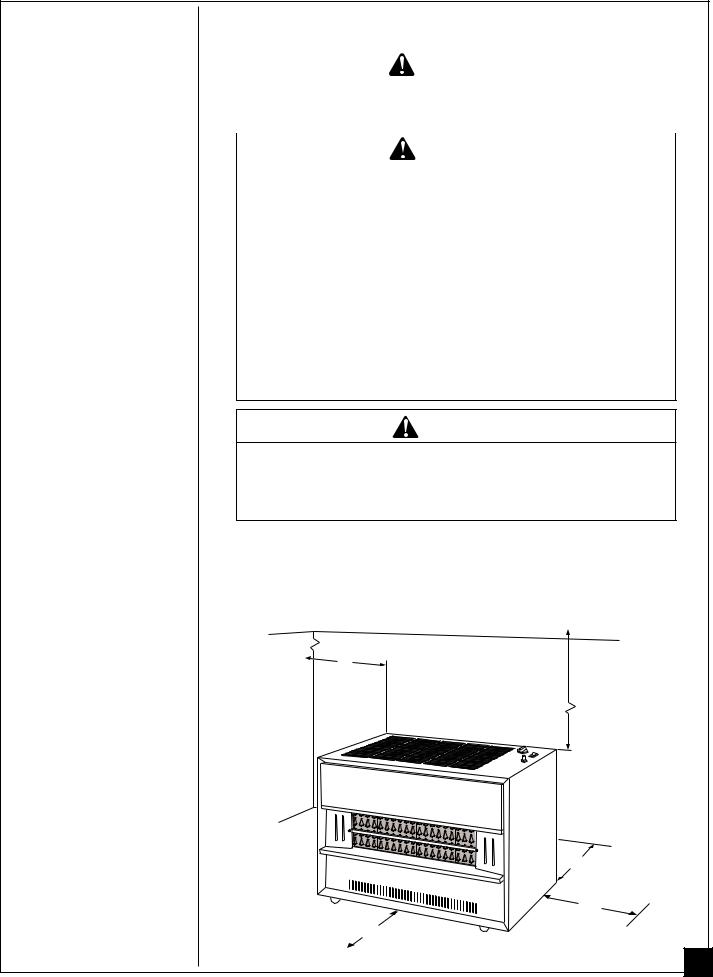
Maintain the minimum clearances shown in Figure 3, |
|
|
|
below. If you can, provide greater clearances. |
|
|
|
|
|
|
|
|
|
|
|
WARNING ICON G 001 |
WARNING |
|
|
Never install the heater |
|
•in a mobile home or a recreational vehicle.
•where curtains, furniture, clothing, or other flammable objects are less than 48 inches from the front, 53 inches from the top, 12 inches from the right side and 6 inches from the left side and back of heater.
•directly on carpeting, tile, or other combustible materials other than wood flooring. Place heater on metal or wood panel extending the full width and depth of heater.
•as a fireplace insert.
•in high traffic areas.
•in windy or drafty areas.
CAUTION
WARNING ICON |
G 001 |
If you install the heater in a home garage
•heater pilot and burner must be at least 18 inches above floor
•locate heater where moving vehicle will not hit it.
For convenience and efficiency, install heater
•where there is easy access for operation, inspection, and service.
•in coldest part of room.
•near an electrical outlet if heater has blower or if you are planning to add blower to heater. See Accessories, page 37 for blower.
|
CEILING |
6" |
|
Minimum |
53" |
|
Minimum |
Left |
Right |
|
|
Side |
|
|
|
Side |
|
|
|
|
|
|
|
|
|
6" Minimum |
|
|
|
from Back |
|
|
|
12" |
|
|
48" Minimum from |
Minimum |
|
|
|
|
|
|
Front of Heater |
Continued |
|
|
Figure 3 - Heater Clearances |
7 |
|
|
|
100791
INSTALLING |
VENTING HEATER |
|
HEATER |
Note: Venting/chimney materials are not supplied with heater. |
|
|
|
|
Continued |
|
|
|
WARNING ICON G 001 WARNING |
|
|
|
|
A qualified service person must install the venting system for this heater. If venting system is not properly installed and maintained, the vent safety shut-off system will prevent the heater from running. Follow all local codes.
WARNING
WARNING ICON |
G 001 |
This heater has a vent safety shut-off system. This system shuts off the heater gas supply if you do not vent heater properly or the venting system is blocked. Do not operate heater if not properly vented. Do not tamper with the vent safety shut-off system. Carbon monoxide poisoning and death may result.
WARNING
WARNING ICON |
G 001 |
When venting this heater, follow the safety information listed below.
•Never vent heater to another room or inside a building. Only vent heater to the outdoors.
•Do not vent heater exhaust to a chimney or flue serving another solid-fuel-burning or gas appliance.
•We recommend you use flues classified as prefabricated or masonry all-fuel chimney or type-B vent. See
Vent Types, page 10.
•If using old vent, check vent for soot, creosote, and loose particles. If vent is damaged, repair or replace it before using heater.
•Extend the vertical section of vent pipe at least three feet above roof penetration.
•Extend the vertical section of vent pipe at least two feet above the highest point of any roof within ten feet.
•The horizontal run of vent pipe should rise at least 1/4 inch for each foot of run.
•Support the vent pipe at least every five feet along its length. Do not use combustible materials to support vent pipe.
•Never extend vent pipe horizontally through outside wall and terminate. You must connect a vertical run of vent pipe to the horizontal run. The vertical run must be at least 25% longer than the horizontal run.
•Install vent or chimney cap that is approved for use with vented gas room heaters.
•Do not use vent pipe smaller in diameter than that of the heater draft hood outlet.
•Do not use dampers in the vent pipes.
•Vertical height of vent must be greater than five feet above vent connection at draft hood.
8
100791
INSTALLING HEATER
Continued
VENTING HEATER (continued)
 WARNING
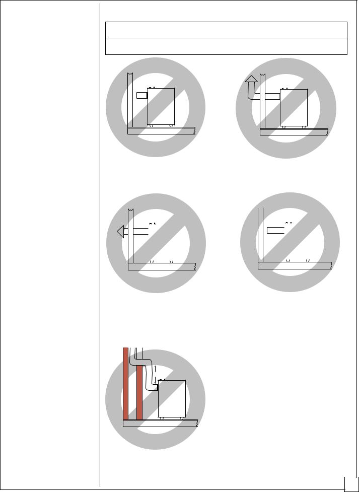
Do not vent heater in any of the following ways (see Figure 4)
Heater must be vented to the out- |
The vertical section of vent pipe must |
|||||||||||
doors. Never vent heater to another |
extend at least two feet above the |
|||||||||||
room or inside a building. |
highest point of any roof within ten |
|||||||||||
|
|
|
|
|
feet. |
|||||||
|
|
|
|
|
|
|
|
|
|
|
|
|
|
|
|
|
|
|
|
|
|
|
|
|
|
|
|
|
|
|
|
|
|
|
|
|
|
|
|
|
|
|
|
|
|
|
|
|
|
|
|
|
|
|
|
|
|
|
|
|
|
|
|
|
|
|
|
|
|
|
|
|
|
|
|
|
|
|
|
|
|
|
|
|
|
|
|
|
|
|
|
|
|
|
|
|
|
|
|
|
|
|
|
Never extend vent pipe horizontally |
Never extend vent pipe horizontally |
|||||
through a chimney or flue. You must |
||||||
through outside wall and terminate. |
||||||
connect a vertical run of vent pipe to |
||||||
You must connect a vertical run of |
||||||
the horizontal run. The vertical run |
||||||
vent pipe to the horizontal run. The |
||||||
must be at least 25% longer or five |
||||||
vertical run must be at least 25% |
||||||
feet minimum than the horizontal run. |
||||||
longer than the horizontal run. |
||||||
|
||||||
|
|
|
|
|
|
|
|
|
|
|
|
|
|
|
|
|
|
|
|
|
Less than 5' between elbows
Vertical run of pipe must be at least five feet from elbow to elbow.
Figure 4 - Improper Venting Systems |
|
|
|
|
Continued |
9 |
|||
|
||||
|
|
|
||
|
|
|
|
|
100791
INSTALLING |
VENTING HEATER (continued) |
HEATER |
Proper Size Vent |
|
To safely vent heater, the vent connector pipe must be the same diameter as the draft Continued hood outlet on the rear of the heater. Pipe that is too small can cause flue gas to spill
from the heater. Fasten vent connector to the draft hood outlet with a sheet metal screw.
Vent Types
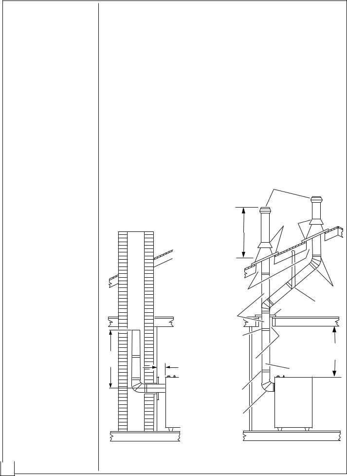
Prefabricated or Masonry All-Fuel Chimney - This is a masonry chimney or a residential-type prefabricated chimney. Only use prefabricated chimneys listed by Underwriters Laboratories (UL), Inc.
Type-B Vent - These vents are made of noncombustible, corrosion resistant material. They are certified by a nationally recognized testing agency. Type-B vents are double-walled pipe. Clearances to combustible construction must be in accordance with the listing of the particular type-B vent. Type-B vents are currently listed as B-1, B-1 1/2, and B-2.
The illustrations below show both vent types. The illustration shows typical construction of each type of venting system. Minimum clearances and lengths are added to the illustrations.
Vent Cap |
Seal Around |
Collar and |
|
Must Be At |
Flashing |
Least 2 Feet |
|
Above |
|
Highest Point |
|
Within 10 |
|
Feet. |
|
|
Maintain Listed |
|
Lock |
|
Clearance of Vent |
|
|
|
|
Joints |
|
|
|
|
|
|
|
Position |
Support |
|
|
Firestop |
|
|
Support If |
Laterals |
|
|
|
||
|
|
|
|
|
Necessary |
|
|
|
Lock Joints |
Maintain Listed |
|
|
|
Clearance of |
53" |
|
6" |
Vent |
|
5' |
|
Min. |
|
Min. |
Min. |
|
|
|
Vertical Vent |
||
|
|
||
|
Lock Joints |
|
|
|
Heater |
Heater |
|
|
Vent |
|
|
|
|
|
|
|
Connector |
|
|
|
Prefabricated or Masonry |
Type-B Vent |
|
|
All-Fuel Chimney |
|
|
|
Figure 5 - Typical Construction of Venting Systems |
||
10 |
|||
|
|
|
|
100791
INSTALLING |
CONNECTING TO GAS SUPPLY |
|||
HEATER |
|
|
|
|
|
WARNING ICON G 001 WARNING |
|
||
Continued |
|
|
|
|
|
A qualified service person must connect heater to gas |
|
||
|
|
|
||
|
|
supply. Follow all local codes. |
|
|
|
|
|
|
|
|
|
|
|
|
|
|
WARNING ICON G 001 CAUTION |
|
|
|
|
Never connect heater directly to the propane supply. |
|
|
|
|
This heater requires an external regulator (not sup- |
|
|
|
|
plied). Install the external regulator between the heater |
|
|
|
|
and propane supply. |
|
|
|
|
|
|
|
|
The installer must supply an external regulator. The external regulator will reduce |
|||
|
incoming gas pressure. You must reduce incoming gas pressure to between 11 and |
|||
|
14 inches of water. If you do not reduce incoming gas pressure, heater regulator |
|||
|
damage could occur. Install external regulator with the vent pointing down as |
|||
|
shown in Figure 6. Pointing the vent down protects it from freezing rain or sleet. |
|||
External Regulator
BULK PROPANE
TANK
Vent Pointing Down
Figure 6 - External Regulator with Vent Pointing Down
CAUTION
WARNING ICON |
G 001 |
Use only new, black iron or steel pipe. Internally-tinned copper tubing may be used in certain areas. Check your local codes. Use pipe that is 1/2" in diameter or greater to allow proper gas volume to heater. If pipe is too small, undue loss of pressure will occur.
The gas supply line to your heater must be 1/2 inch in diameter or larger. If the supply line branches to serve two or more heaters, the line from the branch back to the external regulator must be doubled or tripled, etc., in size (depending upon the number of heaters). Example for 1/2 inch diameter supply line: If the supply line branches to serve two heaters, the line diameter from the branch back to the external regulator must be at least 1 inch. If three heaters are served, the line diameter from the branch back to the external regulator must be at least 1 1/2 inches.
Note: If gas supply line total length exceeds forty feet, use a larger diameter pipe. Use pipe that is the next size larger than the heater control valve fitting.
Continued 11
100791
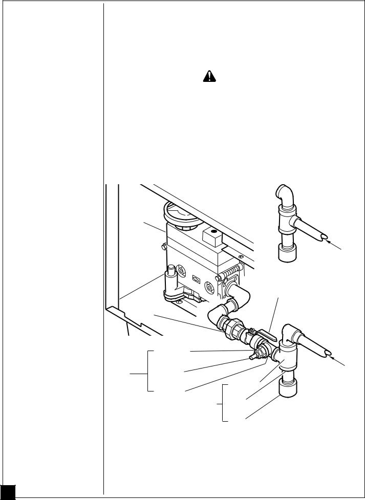
INSTALLING |
Installation must include a manual shutoff valve, ground joint union, plugged 1/8" |
|||||||||
|
||||||||||
HEATER |
NPT tap and a sediment trap. Locate NPT tap within reach for test gauge hook up. |
|||||||||
NPT tap must be upstream from heater (see Figure 7). |
||||||||||
Continued |
Apply pipe joint sealant lightly to male threads. This will prevent excess sealant |
|||||||||
|
from going into pipe. Excess sealant in pipe could result in clogged heater valves. |
|||||||||
|
|
|
|
|
|
|
|
|
|
|
|
|
|
|
|
|
|
WARNING ICON G 001 |
CAUTION |
|
|
|
|
Use pipe joint sealant that is resistant to liquid petro- |
|
|
||||||
|
|
leum (LP) gas. |
|
|
|
|||||
|
|
|
|
|
||||||
|
Install sediment trap in supply line as shown in Figure 7. Locate sediment trap |
|||||||||
|
where it is within reach for cleaning. Locate sediment trap where trapped matter is |
|||||||||
|
not likely to freeze. A sediment trap traps moisture and contaminants. This keeps |
|||||||||
|
them from going into heater controls. If sediment trap is not installed or is installed |
|||||||||
|
wrong, heater may not run properly. |
|
|
|
||||||
|
IMPORTANT: Use two pipe wrenches when connecting gas piping to gas control |
|||||||||
|
valve of heater. This will prevent turning or damaging control valve. |
|||||||||
|
|
|
|
|
|
|
|
Acceptable |
||
|
|
|
|
|
|
|
|
construction |
||
|
|
Control |
|
|
|
|
|
of inlet gas |
||
|
|
|
|
|
|
|
||||
|
|
|
|
|
|
|
line |
|||
|
|
Valve |
|
|
|
|
|
|
|
|
|
|
|
|
|
|
|||||
|
|
|
|
From External |
|
|
|
|
Regulator (11" |
|
|
|
Manual |
W.C. Min** to |
|
|
|
14" W.C. Max) |
|
|
|
|
Shutoff |
|
|
Ground |
Valve * |
|
|
|
|
|
||
|
Joint |
|
|
|
|
Union |
|
|
Preferred |
|
|
|
|
construction |
|
|
|
|
of inlet gas |
|
|
Reducer |
|
line |
|
|
|
|
|
|
|
Bushing to |
|
|
|
Test |
1/8" NPT |
|
|
|
1/8" NPT |
|
From |
|
|
Gauge |
|
||
|
|
External |
||
|
Connection* |
Plug Tap |
Tee Joint |
|
|
Regulator |
|||
|
|
Tee Joint |
||
|
|
Pipe |
(11" W.C. |
|
|
|
|
||
|
|
Sediment |
Min** to |
|
|
|
Nipple |
||
|
|
Trap |
14" W.C. |
|
|
|
|
||
|
|
|
Cap |
Max) |
|
|
|
|
|
|
|
Figure 7 - Gas Connection |
|
|
|
* An A.G.A. design-certified manual shutoff valve with 1/8" NPT tap is an |
|||
|
acceptable alternative to test gauge connection. Purchase the optional A.G.A. |
|||
|
design-certified manual shutoff valve from your dealer. See Accessories, page 37. |
|||
12 |
** For purposes of input adjustment. |
|
|
|
|
|
|
|
|
|
|
|
|
100791 |
INSTALLING CHECKING GAS CONNECTIONS |
||||||
HEATER |
|
WARNING ICON G 001 WARNING |
|
|||
Continued |
|
Test all gas piping and connections for leaks after install- |
|
|
|
|
|
|
ing or servicing. Correct all leaks at once. |
|
|||
|
|
|
|
|
|
|
|
|
|
|
|
||
|
|
WARNING ICON G 001 WARNING |
|
|
||
|
|
Never use an open flame to check for a leak. Apply a |
|
|
|
|
|
|
mixture of liquid soap and water to all joints. Bubbles |
|
|||
|
|
forming show a leak. Correct all leaks at once. |
|
|||
|
|
|
|
|
||
|
|
|
||||
|
|
WARNING ICON G 001 CAUTION |
|
|
||
|
|
Make sure external regulator has been installed be- |
|
|
|
|
|
|
tween propane supply and heater. See guidelines under |
|
|||
|
|
Connecting to Gas Supply, page 11. |
|
|||
|
|
|
||||
Pressure Testing Gas Supply Piping System |
||||||
Test Pressures In Excess of 1/2 PSIG |
||||||
1. |
Disconnect heater and its individual manual shutoff valve from gas supply |
|||||
|
pipe. Pressures in excess of 1/2 PSIG will damage heater regulator. |
|||||
2. |
Cap off open end of gas pipe where manual shutoff valve was connected. |
|||||
3. |
Pressurize supply piping system by either using compressed air or opening |
|||||
|
propane supply tank valve. |
|||||
4. |
Check all joints of gas supply piping system. Apply mixture of liquid soap and |
|||||
|
water to gas joints. Bubbles forming show a leak. |
|||||
5. |
Correct all leaks at once. |
|||||
6. |
Re-connect heater and manual shutoff valve to gas supply. Check re-connected |
|||||
|
fittings for leaks. |
|||||
Test Pressures Equal To or Less Than 1/2 PSIG
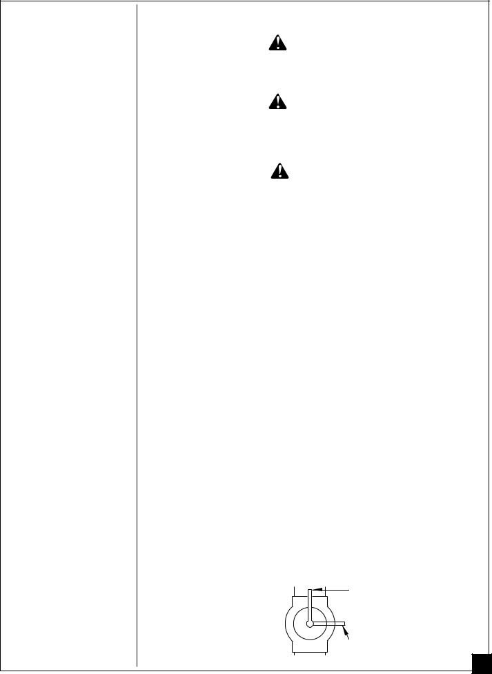
1.Close manual shutoff valve (see Figure 8).
2.Pressurize supply piping system by either using compressed air or opening propane supply tank valve.
3.Check all joints from propane supply tank to manual shutoff valve. Apply mixture of liquid soap and water to gas joints. Bubbles forming show a leak.
4.Correct all leaks at once.
Pressure Testing Heater Gas Connections
1.Open manual shutoff valve (see Figure 8).
2.Open propane supply tank valve.
3.Make sure control knob of heater is in the OFF position.
4.Check all joints from manual shutoff valve to control valve on heater. Apply mixture of liquid soap and water to gas joints. Bubbles forming show a leak.
5.Correct all leaks at once.
6.Light heater (see Operating Heater, pages 21 through 23). Check the rest of the internal joints for leaks.
7.Turn off heater (see To Turn Off Gas to Appliance, page 23).
PO On Position
Off Position |
Continued |
Figure 8 - Manual Shutoff Valve |
13 |
100791
INSTALLING |
INSTALLING RADIANTS |
HEATER |
WARNING ICON G 001 WARNING |
Continued |
Carefully handle the glass panel. Glass edges are |
|
rounded and buffed to prevent cuts, however, chipped |
|
or broken sections of glass can present sharp edges. |
|
These sharp edges can cut skin. |
|
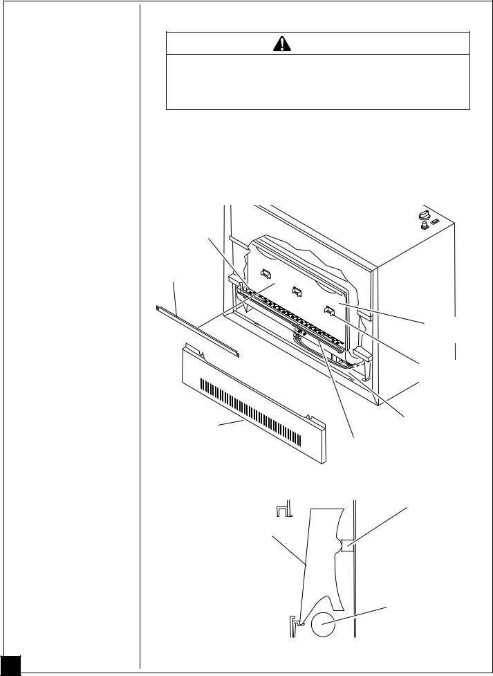
1. Remove glass guard from across opening at front of heater (see Figure 9). |
|
2. Place radiants into combustion chamber through opening at front of heater. |
|
Front of radiant sits on front radiant support (see Figure 10). Back of radiant |
|
rests on back radiant support (see Figures 9 and 10). |
|
Note: Radiants should never come in contact with burner flame. Contact with |
|
flame may cause carbon or soot deposits on radiants. |
|
Burner |
|
Glass |
|
Guard |
|
Combustion |
|
|
Chamber |
|
|
Back Radiant |
|
|
Support |
|
Lower |
Lower Front |
|
Access Area |
||
|
||
Front Access |
||
Panel |
Glass Retaining |
|
Channel |
||
|
||
|
Figure 9 - Location of Radiants |
|
|
Back Radiant Support |
|
|
Radiant |
|
Burner
Front Radiant Support 
Figure 10 - Position of Radiant
14
100791
 Loading...