


 Loading...
Desa E36L, E36LB, E36LH, E36LBH, E32LB User Manual
...
ELECTRIC FIREPLACE
OWNER’S OPERATION AND INSTALLATION MANUAL
MODELS E32L, E32LB, E32LH, E32LBH,
E36L, E36LB, E36LH AND E36LBH
PLEASE READ THIS MANUAL BEFORE INSTALLING AND USING APPLIANCE.
 WARNING: If the information in this manual is not followedexactly,anelectricalshockorfiremayresultcausing property damage, personal injury or loss of life.
FOR YOUR SAFETY
—Do not store or use gasoline or other flammable vapors and liquids in the vicinity of this or any other appliance.
—Installation and service must be performed by a qualified service agency.
INSTALLER: Leave this manual with the appliance.
CONSUMER: Retain this manual for future reference.
For more information, visit www.desatech.com
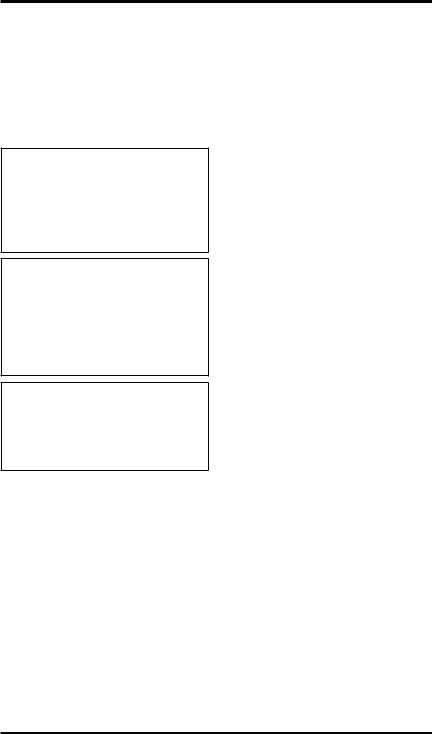
Table of Contents
Safety................................................................... |
2 |
Maintenance....................................................... |
16 |
Product Specification............................................ |
3 |
Technical Service............................................... |
23 |
Installation............................................................ |
3 |
Replacement Parts............................................. |
23 |
Features and Operation....................................... |
7 |
Parts................................................................... |
24 |
Accessory Installation........................................... |
8 |
Accessories........................................................ |
27 |
Troubleshooting.................................................. |
14 |
Warranty............................................... |
Back Cover |
Wiring Diagram................................................... |
15 |
|
|
Safety
 WARNING: Electrical wiring must comply with local building codes and other applicable regulations to reduce the risk of fire, electrical shock and injury to persons.
 WARNING: Do not use this fireplace if any part of it has been under water. Immediately call a qualified service techniciantoinspectthefireplaceand replace any part of the electrical system.
 CAUTION: Extreme caution is necessary when any heater is usedbyornearchildrenorinvalids and whenever the heater is left operating and unattended.
1.Read all instructions before using this fireplace.
2.This fireplace is hot when in use. To avoid burns, do not let bare skin touch hot surfaces. If provided, use handles when accessing fireplace controls. Keep combustible materials, such as furniture, pillows, bedding, papers, clothes, and curtains at least 3 feet from front of fireplace.
3.Extreme caution is necessary when any heater is used by or near children or invalids and whenever heater is left operating and unattended.
4.Always place main power switch in OFF position when not in use.
5.Do not operate fireplace if any part has been damaged or is malfunctioning.
6.Any repairs to this fireplace should be done by a qualified service person.
7.Do not use outdoors.
8.This fireplace is approved for installation in bedrooms.
9.Under no circumstances should this fireplace be modified. Parts having to be removed for servicing must be replaced prior to operating this fireplace.
10.This fireplace is not intended for use in bathrooms, laundry areas and similar locations where it would be subject to excessive moisture.
11.This fireplace may not be installed outdoors or in an unenclosed space where exposed to the elements.
12.To disconnect this fireplace, turn off at circuit breaker or fuse panel.
13.This appliance, must be electrically grounded in accordance with local codes and the National Electric Code, ANSI/ NFPA No. 70 or in Canada with CSA C22.1 Canadian Electrical code.
14.Do not insert or allow foreign objects to enter any ventilation or exhaust openings. This may cause an electrical shock, fire or damage to fireplace.
15.To prevent a possible fire do not block air intakes or exhaust.
16.This fireplace has hot and arcing or sparking parts inside. Do not use in areas where gasoline, paint or flammable liquids are used or stored. This fireplace should not be used to dry clothing or for hanging decorations.
17.Use this fireplace only as described. Any other use not recommended by the manufacturer may cause fire, electric shock or injury to persons.
18.SAVE THESE INSTRUCTIONS.
|
www.desatech.com |
111076-01F |
Product Specification
E32 = 221/4"
 E36 = 241/4"
E32 = 155/8" |
TOP |
|
|
|
|
||
E36 = 17" |
|
|
|
|
5/8" |
|
|
|
E32 = 61/2" |
|
|
|
E36 = 51/4" |
|
|
|
|
E32 = 7" |
|
/8" |
/8" |
E36 = 8" |
|
E32 = 321 |
E36 = 361 " " |
= 333/8" = 37" |
= 183/8" = 21" |
|
283/8 313/4 |
E32 E36 |
E32 E36 |
|
E32 = E36 = |
|
|
|
ELECTRICAL SPECIFICATIONS |
|
|||
|
Voltage: |
|
|
120 VAC, 60 Hz |
|
E32 = 161/4" |
Total Amps: |
|
|
12.5 Amps |
|
E36 = 175/8" |
Total Watts: |
|
|
1500 Watts |
|
17/8" |
Heater Rating: |
|
1100 Watts |
|
|
Max. Bulb Rating: |
100 Watts |
|
|||
|
Use only on 15 amp circuit |
|
|||
|
E32 = 363/8" |
|
|
|
|
E32 = 293/8"E36 = 43" |
|
|
E32 = 8" |
|
|
E36 = 35" |
|
|
|
E36 = 51/4" |
|
|
/8" |
/4" |
NailTo Location |
|
|
|
= 325 |
= 361 |
" " |
||
|
E32 E36 |
" " |
283/8 313/4 |
||
|
|
|
7/8 |
1/2 |
= = |
|
|
|
= 32 |
= 36 |
E32 E36 |
|
|
|
E32 E36 |
|
|
LEFT SIDE |
E32 = 345/8" |
RIGHT SIDE |
|
E36 = 411/4" |
|
E32 |
= 353/8" To Nail |
|
E36 |
= 42" Location |
|
FRONT
Figure 1 - Unit Dimensions
Installation
LOCATING FIREPLACE
Plan where to locate and frame fireplace. Before installation consider the following:
1.Fireplace location must allow for wall and ceiling clearances (see Installation Clearances, page 4).
2.Fireplace screen should not be exposed to direct sunlight from windows or doors.
3.A 15 amp, 120 Volt, 60 Hz circuit with proper ground must be available. A dedicated circuit should be provided to avoid circuit breaker trips or blown fuses.
Flush Installations are recommended where living space is limited or at a premium. Since space required to enclose fireplace would be located beyond an outside wall, this installation would require additional planning and construction. Check local codes for any restrictions.
Projected Installations can extend any distance into room.Aprojection may be ideal for a new addition on an existing, finished wall.
Corner Installations make use of space that may not normally be used and provides a wider and more efficient viewing angle and heat distribution.
Internal Wall Installations provide a discrete option for room separation and can also be an ideal addition to an existing wall.
Internal Wall |
Corner |
Installation |
Installation |
Flush
Full Projection Installation
Installation
Figure 2 - Possible Installation Locations
111076-01F |
www.desatech.com |
INSTALLATION
Continued
INSTALLATION CLEARANCES
Minimum clearances to combustible construction are:
• Top, Back and Sides of Recessed |
|
|
|
|
|
||||
|
Cabinet. . . . . . . . . . |
. |
0" Min. |
• |
Floor . . . . . . . . . |
. . |
. |
0" Min. |
|
• Drywall to Sides of Front Face . |
. |
0" Min. |
• |
Front. . . . . . . . . . . .36" Min. |
|||||
• |
Framing at Nailing Flanges. . . |
|
.0" Min. |
• |
Perpendicular Side Wall . . |
. |
. |
10" Min. |
|
• |
Ceiling to Opening. . . . . . |
.36" Min. |
|
|
|
|
|
||
Mantel Clearances |
|
|
|
|
|
|
|
|
|
For mantel clearances see Figures 3 and 4. |
|
|
|
|
|
||||
|
|
|
|
|
|
Facing Material May |
|
|
|
|
|
|
|
|
|
Be Noncombustible |
|
|
|
|
|
|
|
|
|
Wall Treatments or |
|
|
|
|
|
|
|
12" Ref. |
|
Combustible Wood |
|
|
|
|
|
|
|
10 1/2" |
|
Combustible Wood |
|
|
|
|
|
|
|
|
|
|
|
|
|
|
|
|
4 1/2" |
|
Mantels and Trims |
|
|
|
|
|
|
|
|
1 1/2" |
May Extend Above |
|
|
|
|
|
30° |
|
|
|
|
Profile Shown when |
|
|
|
|
|
|
|
|
|
Maintained within |
|
|
|
|
|
|
|
|
|
30° Parameter |
|
|
|
|
|
|
|
|
|
Shown |
|
|
|
|
16 5/8" |
1 3/4" |
|
|
|
Framed |
|
|
|
|
|
|
|
|
Material |
|
|
|
|
|
Ref. |
|
|
|
|
|
|
|
|
|
|
|
|
|
|
|
|
|
|
|
|
13 3/4" |
|
|
|
|
|
|
|
|
|
10 1/2" Min. |
9 5/8" Ref. |
Top of Cabinet |
|
|
|
||
|
|
|
|
|
|
||||
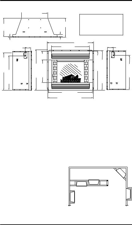
Note: All Mantel Clearances  are Measured from Top of Fireplace Opening
Figure 3 - Mantel Clearances
Top View of Fireplace

 3"
3"

Edge of Firebox
Opening
|
Safe Zone |
Combustible |
|
30° |
5" |
||
1 3/4" Max. |
MaterialMust |
||
|
|||
|
|
Not Overlap |
|
|
Minimum 10" from |
Front Face |
|
|
|
||
|
Perpendicular Side Wall |
|
Figure 4 - Mantel Side Clearances
www.desatech.com |
111076-01F |
INSTALLATION
Continued
BUILT-IN INSTALLATION
Built-in installations require a framed enclosure constructed of 2" x 4" or heavier lumber and sized in accordance with Figure 5. This allows unit to slide into opening and be nailed to stud at sides and top nailing flanges. These flanges accept 5/8" drywall or plywood board to finish unit flush to face. Optional trim accessories are available that will extend 1/2" over rough edge of wall opening (see Accessories, page 25).
IMPORTANT: If installing a perimeter trim kit, you must install shoulder screws before inserting fireplace into opening. See instructions included with trim kit. If installing a mantel, you must follow clearance instructions (see
Installation Clearances, page 4).
A hearth extension is suggested for a more pleasing appearance. The fireplace may be raised on a wood or non-combustible platform supporting its entire width and depth and extending in front of the fireplace as long as louvers are not obstructed.
Note: When installing fireplace in cold climates against a non-insulated exterior wall, wall must be fully insulated in accordance with local building code.
Platform/Subflooring
VE32 = 32 5/8"
VE36 = 36 1/4"
VE32 = 15 7/8"
VE36 = 17 1/4"
VE32 = 34 5/8"
VE36 = 41 1/4"
Figure 5 - Framing Dimensions
|
|
|
|
|
These Dimensions |
||||
|
|
|
|
|
Allow for 11 5/8" of |
||||
VE32 = 37 5/8" |
|
|
Clearance to Side |
||||||
VE36 = 42 3/8" |
|
|
Wall of Fireplace |
||||||
|
|
|
|
|
and 10' Clearance |
||||
|
|
|
|
|
|||||
VE32 = 26 5/8" |
|
|
to Perpendicular |
||||||
VE36 = 29 3/8" |
|
|
Side Walls |
||||||
|
|
|
VE32 = 52 3/4" |
|
11 5/8" |
|
|||
|
|
|
|
|
|||||
|
|
|
|
|
|||||
|
|
|
|
|
|
||||
|
|
|
|
|
|
|
|
|
|
|
|
|
VE36 = 58 1/4" |
|
|||||
Figure 6 - Corner Dimensions
ELECTRICAL INSTALLATION
 WARNING: Any electrical rewiring of this appliance must be done by a qualified electrician. This wiring must be done in accordancewithlocalcodesand/or in the U.S.A. with the current, NationalElectricalCodeANSI/NFPA No 70 and in Canada with CSA C22.1 Canadian Electric code.
This fireplace should be connected to a dedicated 15 Amp, circuit as other appliances may cause the circuit breaker to trip or fuse to blow when fireplace is in operation.
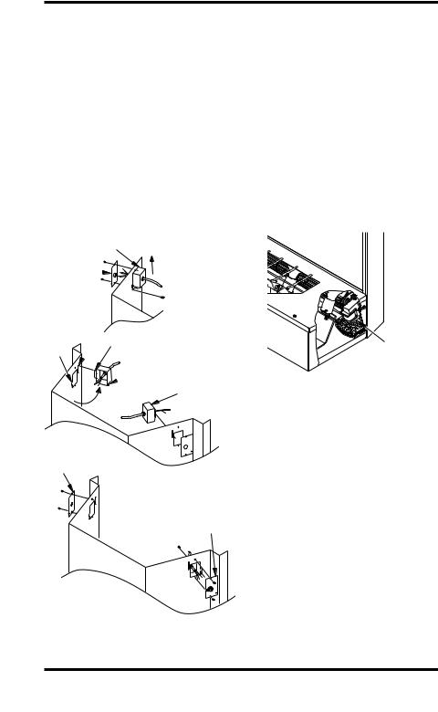
Ajunction box with universal strain adaptor is provided to hard wire unit to a 15 amp, 120 Volt 60 Hz grounded circuit. If necessary, junction box may be relocated to route supply to left side.
1.Remove 2 screws and outer cover on right side (see Figure 7, page 6).
2.Remove inner screw securing junction box.
3.Slide junction box up until mounting tab is lined up to notch in outer cabinet.
4.Swing box out and slip retaining flange out through slot in outer cabinet.
5.Remove 2 screws and outer cover on left side and reattach on right side of outer cabinet.
111076-01F |
www.desatech.com |
INSTALLATION
Continued
6.Swing junction box with harness to left side while pulling sufficient length of harness out through control panel cover to reach mounting location on left side.
7.Reinsert retaining flange through slot and swing screw mounting tab back through notch as before.
8.Slide junction box down until mounting holes line up and replace inner retaining cover.
9.Pull end of 3 wire Romex supply line through universal strain relief bushing in remaining cover.
10.Strip back outer Romex to about 4” and connect black, white and green wires accordingly using approved connectors.
Junction Box
Screws  and
and
Outer
Cover
Slot Retaining
Notch  Flange
Mounting
 Tab
Tab
Junction Box
11.Tuck tailing wires into junction box and replace cover using 2 remaining screws.
12.Tighten down strain adjustment on universal bushing until Romex sheathing is secured.
IMPORTANT: Inspect components and wiring for damage before connecting power to unit. If any components are found damaged, contact an authorized dealer for original DESA Heating Products replacement part(s) or call DESA Heating Products at 1-866-872-6040 for referral.
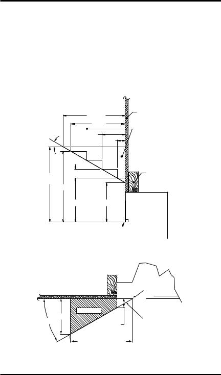
IMPORTANT: Prior to operation remove foam shipping brace located under motor mount (see Figure 8).
Motor
 Mount
Mount
Foam
Shipping
Brace
Figure 8 - Removing Shipping Brace
Screws and
Outer Cover from Other Side
Cover with
Universal
Strain Relief
Figure 7 - Relocating Junction Box to Left
www.desatech.com |
111076-01F |
INSTALLATION
Continued
Lamps and lava Rock
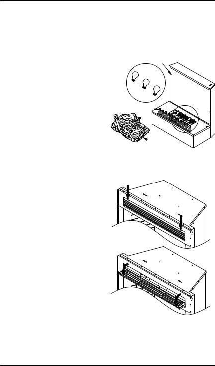
Before operating fireplace, lamp bulbs must be inspected and lava rock may be added if desired.
1.Lift log bed off hearth base to gain access to lamp fixtures (log bed is attached with contact magnets).
2.Turn on power to light circuit and check that all bulbs are operating. Bulb placement front left to right are red, yellow and orange (see Figure 9).
Note: If bulbs need replacing, see Replacing Light Bulbs, page 16. Be careful not to tear or damage reflective strips. If they have come loose, ends can be easily reattached or replaced at support brackets. See Replacing Reflective Ribbons, page 21.
3.Center log bed over opening between viewing panel screen and grate.
4.Cover remaining hearth area with 1/4" of lava rock (provided), if desired.
Viewing Panel
Screen
Red
Yellow
Orange
Grate 

 Log Bed
Figure 9 - Bulb Placement
Features and Operation
This electronic fireplace series features a random flame effect, and a realistic log bed with glistening embers that can be adjusted for flame speed and light intensity.
E36/32LH models have a circulating heater, rated at 1100 Watts. Models E36/32LB and E36/32LBH include a hand detailed, textured,
red-brick lining.
Access controls by pulling two handle tabs of upper louver until panel releases from magnetic catches and swings down to open position (see Figure 10).
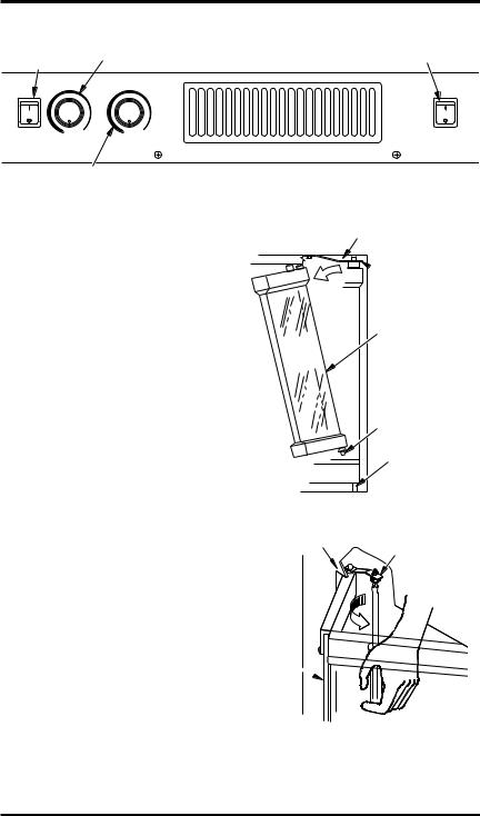
Figure 11, page 8, shows control layout for heater equipped models with main power
switch to flame controls and heater power switch (when equipped) to heating unit. This
allows independent and efficient operation of both features.
Once main power is turned on, flame speed and brightness may be turned on and adjusted independently.
Figure 10 - Accessing Controls
111076-01F |
www.desatech.com |
FEATURES AND OPERATION
Continued
ON/OFF |
Flame Speed |
Heater Switch |
|
Switch |
|||
|
|
MAIN |
HIOFF LOW |
- OFF LOW |
HEATER |
POWER |
|
||
|
FLAME SPEED |
FLAME BRIGHTNESS |
|
Flame Brightness
Figure 11 - Control Panel
Accessory Installation
OPTIONAL GLASS DOORS
Models E36Land E32Lwill accept bifold glass doors that are fully operable or a fixed panel door that limits access to fireplace, (see Accessories, page 25).
Installing Bifold Glass Doors
Follow these steps to install left and right operable panels:
1.With handle down, completely fold panel on its hinges.
2.With handle facing center of firebox opening insert lower pivot pin on door panel into hole in bottom outer edge of firebox opening (see Figure 12).
3.Keep folded door tilted and slide upper two pins into guide track below upper facial edge of firebox opening.
4.Tilt glass assembly fully vertical until outer pivot pin snaps into mounting hole in upper spring clip.
5.Once top and bottom pins are secured, unfold door into closed position.
6.Repeat steps 1 through 5 for opposite door assembly.
7.To adjust doors, slide partially open. Using a Phillips screwdriver, loosen holddown screws on spring clips (see Figure 13).
8.Close both doors until evenly joined at middle and note gap as measured to outer edges of front face.
9.Reopen each door one at a time and retighten the hold-down screw while preserving noted gap at each edge.
10.Repeat process until both doors are evenly joined, spaced and working freely.
Spring Clip
Depress Spring
 Clip to Release
Pivot Pin
Fold Bifold Door
After Releasing
Spring Clip to
Slide Door Out of
Upper Track
Remove Pivot Pin
From Bottom Face
While Sliding Door
Out of Upper Track
Pivot Pin
Figure 12 - Installing/Removing Glass
Doors
Side Front |
|
Face |
Spring Clip |
Partially
Opened
Door 
Figure 13 - Adjust Glass Door
www.desatech.com |
111076-01F |
Accessory Installation
Continued
Removing Bifold Glass Doors
Bifold doors may be removed for replacing or cleaning.
1.Partially open each door and press up on upper spring clip with a screw driver until outer top pivot pin is free of the clip.
2.Fully fold frame assembly and slide upper edge towards center of firebox opening until the guide pins are free of the frame rail (see Figure 12, page 8).
Installing Series Fixed Glass Doors
1.Hold glass door firmly at both handles and insert top pins into clips located below upper facial edge of firebox opening. Make sure top pins snap securely into holes on spring clips (see Figure 14).
2.Push up on glass against tension of spring clips.Swinglowerdoorintofaceuntillower pins clear bottom rail and set into locating holes on each end (see Figure 14).
Note: If pins do not align into spring clips, slightly loosen retaining screws on each clip (see Figure 13, page 8). Reinsert panel into each spring clip and align panel into lower locating holes. Remove panel, finish tighten screws and reinsert panel.
Spring Clip
OPTIONAL BRICK LINERS
Installing or Removing Brick Liner Kits
Brick liner kits are available for Models E36/32(L)(H) (see Accessories, page 25). These brick panels may be installed anytime after fireplace installation is complete.
Follow these steps to install left and right brick panels:
1.Remove glass doors (if equipped). Follow instructions under Optional Glass Doors, page 8.
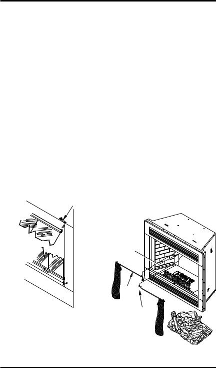
2.Remove each retaining screw holding screen rods and pull entire screen and rod assembly out of locating hole on inside top edge of firebox (see Figure 15).
3.Remove log bed from hearth pan and place in a safe area. Log bed is attached with contact magnets only.
4.Remove two screws holding each refractory bracket to firebox. Pull up and lift out of positioning slot at bottom of hearth pan (see Figure 16, page 10).
Note: E36L and E36LH models require removal of additional hearth brackets and face panels which are held in place by 2 screwsonhearthpanandonescrewattop retainer bracket (see Figure 16, page 10).
Mounting
Holes 
Locating
 Hole
Hole
Screen
Rod
|
Retaining |
Figure 14 - Installing Fixed Glass Doors |
Screw |
Figure 15 - Removing Screen/Rod
Assembly
111076-01F |
www.desatech.com |
|
Loading...