


CVDR30
Desa CVDR30, CVDR24, CPVSR18, CVSR18, CVDR18 User Manual
...
NATURAL GAS LOG
WARNING: If the information in this manual is not
followed exactly, a fire or explosion may result
causing property damage, personal injury, or
loss of life.
— Do not store or use gasoline or other flammable
vapors and liquids in the vicinity of this or any
other appliance.
— WHAT TO DO IF YOU SMELL GAS
• Do not try to light any appliance.
• Do not touch any electrical switch; do not use
any phone in your building.
• Immediately call your gas supplier from a
neighbor’s phone. Follow the gas supplier’s
instructions.
• If you cannot reach your gas supplier, call
the fire department.
— Installation and service must be performed by
a qualified installer, service agency, or the
gas supplier.
WARNING: Improper installa-
tion, adjustment, alteration, ser-
vice, or maintenance can cause
injury or property damage. Re-
fer to this manual for correct
installation and operational
procedures. For assistance or
additional information consult
a qualified installer, service
agency, or the gas supplier.
WARNING: This appliance is
for installation only in a solid-
fuel burning masonry or UL127
factory-built fireplace, con-
structed of noncombustible
material, and connected to a
working flue. (See page 7 for
minimum flue opening.)
WARNING: This is a gas-fired appliance. It uses air (oxygen) from the room in which
it is installed. Provisions for adequate combustion and ventilation air must be
provided. Refer to
Air for Combustion and Ventilation
section on page 4 of this manual.
This appliance may be installed in an aftermarket* manufactured (mobile) home, where not prohibited by
state or local codes.
* Aftermarket: Completion of sale, not for purpose of resale, from the manufacturer
VENTED DECORATIVE APPLIANCES
OWNER’S OPERATION AND INSTALLATION MANUAL
Save this manual for future reference.
RADCO Burner
Models CVSR18,
CVSR24, CPVSR18,
CPVSR24, CVDR18,
CVDR24, and CVDR30
RGA 2-72
APPROVED
TESTED AND
LISTED BY
2
901048
FOR VENTED NATURAL GAS LOGS
RADCO BURNERS
1. This appliance, as supplied, is only for
use with the type of gas indicated on
the rating plate. This appliance is con-
vertible for use with propane/LP, using
the GA9000 or GA9100 pilot kit.
SAFETY
INFORMATION
Carbon Monoxide Poisoning: Early
signs of carbon monoxide poisoning re-
semble the flu, with headaches, dizziness,
or nausea. If you have these signs, the log set
may not be working properly. Get fresh air
at once! Have log set serviced. Some people
are more affected by carbon monoxide than
others. These include pregnant women,
people with heart or lung disease or anemia,
those under the influence of alcohol, and
those at high altitudes.
Natural Gas: Natural gas is odorless. An
odor-making agent is added to the gas. The
odor helps you detect a gas leak. However,
the odor added to the gas can fade. Gas may
be present even though no odor exists.
Make certain you read and understand all
Warnings. Keep this manual for reference.
It is your guide to safe and proper operation
of this log set.
WARNING ICON G 001
WARNINGS
IMPORTANT: Read this owner’s
manual carefully and completely
before trying to assemble, oper-
ate, or service this log set. Im-
proper use of this log set can cause
serious injury or death from burns,
fire, explosion, electrical shock,
and carbon monoxide poisoning.
DANGER: Carbon monoxide
poisoning may lead to death!
WARNING: Any change to this
log set or its controls can be
dangerous.
2. If you smell gas
• shut off gas supply
• do not try to light any appliance
• do not touch any electrical switch; do
not use any phone in your building
• immediately call your gas supplier
from a neighbor’s phone. F ollow the
gas supplier’s instructions
• if you cannot reach your gas supplier ,
call the fire department
3. Never install the log set
• in a recreational vehicle
• where curtains, furniture, clothing, or
other flammable objects are less than
42 inches from the front, top, or sides
of the log set
• in high traffic areas
• in windy or drafty areas
4. Before installing in a solid fuel burn-
ing fireplace, the chimney flue and fire-
box must be cleaned of soot, creosote,
ashes and loose paint by a qualified
chimney cleaner. Creosote will ignite
if highly heated. Inspect chimney flue
for damage.
5. Y ou must operate this log set with a fire-
place screen in place. Make sure fireplace
screen is closed before running log set.
6. This log set is designed to be smoke-
less. If logs ever appear to smoke, turn
off appliance and call a qualified ser-
vice person.
Note:
During initial op-
eration, slight smoking could occur due
to log curing and the burning of manu-
facturing residues. You may wish to add
more ventalation by opening a window .
7. To reduce the creation of soot, follow
the instructions in Cleaning and Main-
tenance, page 20.
8. Do not allow fans to blow directly into
the fireplace. Avoid any drafts that al-
ter burner flame patterns. Ceiling fans
can create drafts that alter burner flame
patterns. Altered burner patterns can
increase sooting.
9. Do not use a blower insert, heat ex-
changer insert or other accessory not
approved for use with this log set.
10. This log set needs fresh, outside air ven-
tilation to run properly. See Air for
Combustion and Ventilation, pages 4
through 6.
11. Do not run log set
• where flammable liquids or vapors
are used or stored
• under dusty conditions
12. Do not burn solid fuel in the fireplace
after installing the log set. Do not use
this log set to cook food or burn paper
or other objects.
13. Log set becomes v ery hot when in use.
Keep children and adults away from hot
surface to avoid burns or clothing igni-
tion. Log set will remain hot for a time
after shut-down. Allow surface to cool
before touching.
14. Carefully supervise young children
when they are in the room with log set.
15. Do not use appliance if any part has been
exposed to or under water . Immediately
call a qualified service technician to in-
spect the room appliance and to replace
any part of the control system (if using
GA9000 or GA9100) and any gas con-
trol which has been under water.
16. To help prevent breakage, new logs
must be broken-in (see Curing logs
page 12).
17. Turn log set off and let cool before ser-
vicing, installing, or repairing. Only a
qualified service person should install,
service, or repair log set.
WARNING: Keep flue open
when operating unit.
3
901048
OWNER’S MANUAL
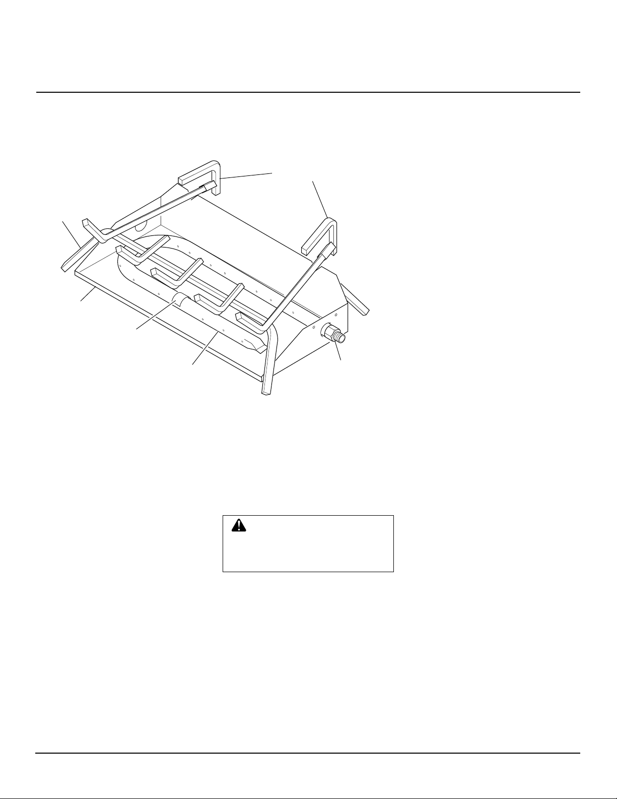
PRODUCT
IDENTIFICATION
Figure 1 - Product Identification (VVDR24 Shown)
OPTIONAL
PRODUCT
FEATURES
ON/OFF SAFETY VALVE/
PILOT KIT AND PROPANE/LP
CONVERSION
An optional valve/safety pilot kit with a
piezo ignitor is available for this appliance.
This system requires no matches, batteries,
or other sources to light. You must use this
optional system for LP conversion. See Ac-
cessories, page 20.
REMOTE CONTROL READY
(MILLIVOLT) SAFETY VALVE/
PILOT KIT
An optional millivolt valve/safety pilot kit
with a piezo ignitor is available for this
appliance. This system requires no matches,
batteries, or other sources to light. This
system may be connected to a wall switch or
hand-held wireless remote control. See Ac-
cessories, page 20.
REMOTE CONTROL
ACCESSORIES
There is an optional hand-held ON/OFF
remote control that can be purchased sepa-
rately for this log set. You must use the
millivolt valve/safety pilot kit to use remote
accessories with this appliance. See Acces-
sories, page 20.
UNPACKING
CAUTION: Do not remove the
metal data plates from the burner
pan. The d ata plates contain im-
portant product information.
1. Remove logs, hearth kit, pan materials,
and hardware from carton.
2. Remove all protective packaging ap-
plied to logs and base for shipment.
3. Check all items for any shipping dam-
age. If damaged, promptly inform
dealer where you bought the product.
LOCAL CODES
Install and use log set with care. Follow all
local codes. In the absence of local codes, use
the latest edition of The National Fuel Gas
Code ANS Z223.1, also known as NFPA 54*.
*Available from:
American National Standards Institute, Inc.
1430 Broadway
New York, NY 10018
National Fire Protection Association, Inc.
Batterymarch Park
Quincy, MA 02269
Grate
Burner
Pan
Burner
Manifold
Burner Inlet
Fitting
Burner
Clamp
Grate Steps
Serial Number ________________________________________
Log Set Model ________________________________________

4
901048
FOR VENTED NATURAL GAS LOGS
RADCO BURNERS
PROVIDING ADEQUATE
VENTILATION
The following are excerpts from National
Fuel Gas Code. NFPA 54/ANS Z223.1, Sec-
tion 5.3, Air for Combustion and Ventila-
tion.
All spaces in homes fall into one of the three
following ventilation classifications:
1. Unusually Tight Construction
2. Unconfined Space
3. Confined Space
The information on pages 4 through 6 will
help you classify your space and provide
adequate ventilation.
Unusually Tight Construction
The air that leaks around doors and win-
dows may provide enough fresh air for
combustion and ventilation. However, in
buildings of unusually tight construction,
you must provide additional fresh air.
Unusually tight construction is de-
fined as construction where:
a. walls and ceilings exposed to the
outside atmosphere have a con-
tinuous water vapor retarder with
a rating of one perm (6x10
-11
kg
per pa-sec-m
2
) or less with open-
ings gasketed or sealed
and
b. weather stripping has been
added on openable windows and
doors
and
c. caulking or sealants are applied
to areas such as joints around
window and door frames, be-
tween sole plates and floors, be-
tween wall-ceiling joints, be-
tween wall panels, at penetra-
tions for plumbing, electrical, and
gas lines, and at other openings.
If your home meets all of the three
criteria above, you must provide ad-
ditional fresh air. See
Ventilation Air
From Outdoors
, page 6.
If your home does not meet all of the
three criteria above, proceed to
De-
termining Fresh-Air Flow For Log Set
Location
, page 5.
Today’s homes are built more energy effi-
cient than ever. New materials, increased
insulation, and new construction methods
help reduce heat loss in homes. Home owners
weather strip and caulk around windows and
doors to keep the cold air out and the warm air
in. During heating months, home owners
want their homes as airtight as possible.
While it is good to make your home energy
efficient, your home needs to breathe. Fresh
air must enter your home. All fuel-burning
appliances need fresh air for proper com-
bustion and ventilation.
Exhaust fans, fireplaces, clothes dryers, and
fuel burning appliances draw air from the
house to operate. You must provide ad-
equate fresh air for these appliances. This
will insure proper venting of vented fuel-
burning appliances.
AIR FOR
COMBUSTION AND
VENTILATION
WARNING: This appliance
shall not be installed in a con-
fined space or unusually tight
construction unless provisions
are provided for adequate com-
bustion and ventilation air. Read
the following instructions to in-
sure proper fresh air for this and
other fuel-burning appliances in
your home.
Confined and Unconfined Space
The National Fuel Gas Code (ANS Z223.1,
1992 Section 5.3) defines a confined space
as a space whose volume is less than 50
cubic feet per 1,000 Btu per hour (4.8 m
3
per
kw) of the aggregate input rating of all
appliances installed in that space and an
unconfined space as a space whose volume
is not less than 50 cubic feet per 1,000 Btu
per hour (4.8 m
3
per kw) of the aggregate
input rating of all appliances installed in that
space. Rooms communicating directly with
the space in which the appliances are in-
stalled*, through openings not furnished
with doors, are considered a part of the
unconfined space.
This log set shall not be installed in a con-
fined space or unusually tight construction
unless provisions are provided for adequate
combustion and ventilation air.
* Adjoining rooms are communicating only
if there are doorless passageways or ventila-
tion grills between them.

5
901048
OWNER’S MANUAL
DETERMINING FRESH-AIR FLOW FOR APPLIANCE LOCATION
Determining if You Have a Confined or Unconfined Space
Use this work sheet to determine if you have a confined or unconfined space.
Space: Includes the room in which you will install appliance plus any adjoining rooms with doorless passageways or ventilation grills
between the rooms.
1. Determine the volume of the space (length x width x height).
Length x Width x Height = _________________cu. ft. (volume of space)
Example:
Space size 20 ft. (length) x 16 ft. (width) x 8 ft. (ceiling height) = 2560 cu. ft. (volume of space)
If additional ventilation to adjoining room is supplied with grills or openings, add the volume of these rooms to the total volume of
the space.
2. Divide the space volume by 50 cubic feet to determine the maximum Btu/Hr the space can support.
_____________ (volume of space) ÷ 50 cu. ft. = (maximum Btu/Hr the space can support)
Example:
2560 cu. ft. (volume of space) ÷ 50 cu. ft. = 51.2 or 51,200 (maximum Btu/Hr the space can support)
3. Add the Btu/Hr of all fuel burning appliances in the space.
Gas fireplace logs _____________ Btu/Hr
Gas water heater* _____________ Btu/Hr
Gas furnace _____________ Btu/Hr
Vented gas heater _____________ Btu/Hr
Vent-free heater _____________ Btu/Hr
Other gas appliances* + _____________ Btu/Hr
Total = _____________ Btu/Hr
* Do not include direct-vent gas appliances. Direct-vent draws combustion air from the outdoors and vents to the outdoors.
4. Compare the maximum Btu/Hr the space can support with the actual amount of Btu/Hr used.
_____________ Btu/Hr (maximum the space can support)
_____________ Btu/Hr (actual amount of Btu/Hr used)
Example:
51,200 Btu/Hr (maximum the space can support)
95,000 Btu/Hr (actual amount of Btu/Hr used)
The space in the above example is a confined space because the actual Btu/Hr used is more than the maximum Btu/Hr the space can support.
You must provide additional fresh air. Your options are as follows:
A. Rework worksheet, adding the space of an adjoining room. If the extra space provides an unconfined space, remove door to adjoin-
ing room or add ventilation grills between rooms. See Ventilation Air From Inside Building, page 6.
B. Vent room directly to the outdoors. See Ventilation Air From Outdoors, page 6.
C. Install a lower Btu/Hr heater, if lower Btu/Hr size makes room unconfined.
If the actual Btu/Hr used is less than the maximum Btu/Hr the space can support, the space is an unconfined space. You will need no
additional fresh air ventilation.
AIR FOR
COMBUSTION AND
VENTILATION
Continued
Example:
Gas water heater 40,000 Btu/Hr
Gas fireplace logs + 55,000 Btu/Hr
Total = 95,000 Btu/Hr
Continued
WARNING: If the area in which the appliance may be operated is smaller than that defined as an unconfined
space or if the building is of unusually tight construction, provide adequate combustion and ventilation air by one
of the methods described in the
National Fuel Gas Code, ANS Z223.1, 1992, Section 5.3
or applicable local codes.
6
901048
FOR VENTED NATURAL GAS LOGS
RADCO BURNERS
AIR FOR
COMBUSTION AND
VENTILATION
Continued
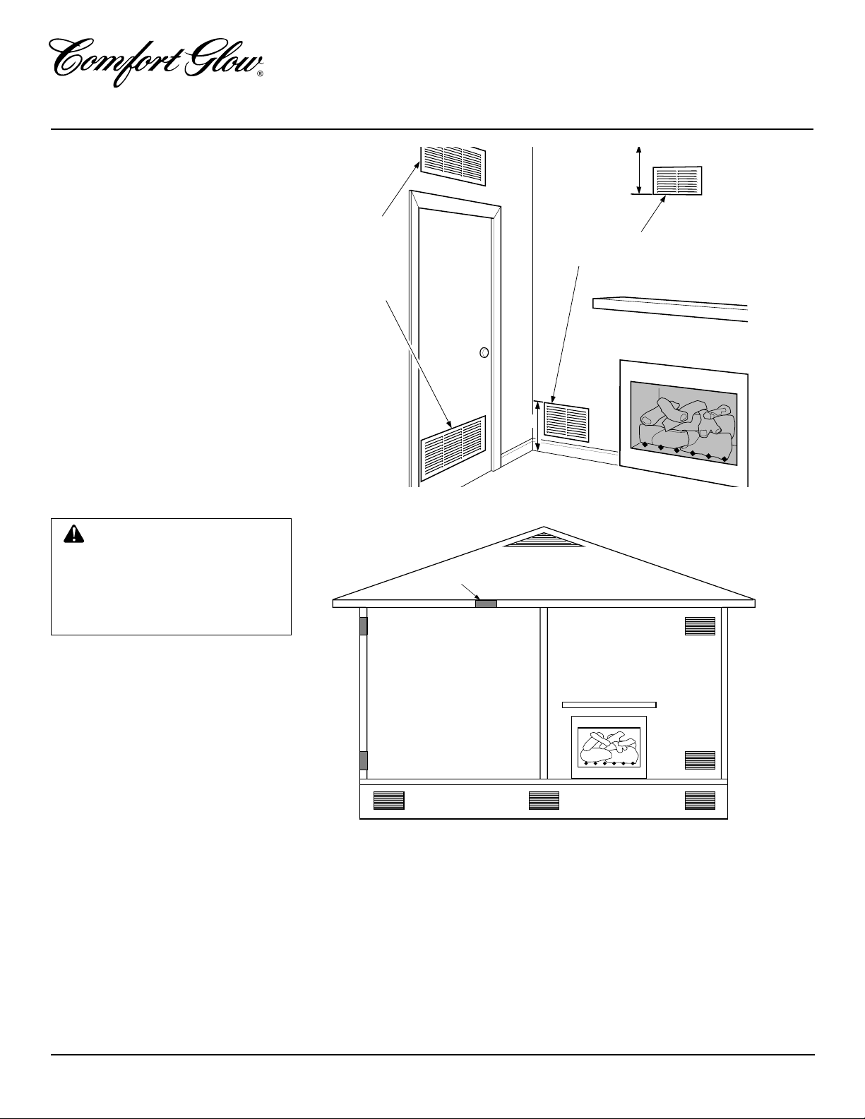
Figure 3 - Ventilation Air from Outdoors
Figure 2 - Ventilation Air from Inside Building
Outlet
Air
Ventilated
Attic
Outlet
Air
Inlet
Air
Inlet Air
Ventilated
Crawl Space
To
Crawl
Space
To Attic
Or
Remove
Door into
Adjoining
Room,
Option
3
Ventilation Grills
Into Adjoining Room,
Option 2
Ventilation
Grills
Into Adjoining
Room,
Option 1
12"
12"
VENTILATION AIR
Ventilation Air From Inside
Building
This fresh air would come from an adjoining
unconfined space. When ventilating to an
adjoining unconfined space, you must pro-
vide two permanent openings: one within
12" of the ceiling and one within 12" of the
floor on the wall connecting the two spaces
(see options 1 and 2, Figure 2). You can also
remove door into adjoining room (see op-
tion 3, Figure 2). Follow the National Fuel
Gas Code NFPA 54/ANS Z223.1, Section
5.3, Air for Combustion and Ventilation for
required size of ventilation grills or ducts.
WARNING: Rework work-
sheet, adding the space of the
adjoining unconfined space. The
combined spaces must have
enough fresh air to supply all
appliances in both spaces.
Ventilation Air From Outdoors
Provide extra fresh air by using ventilation
grills or ducts. You must provide two per-
manent openings: one within 12" of the
ceiling and one within 12" of the floor.
Connect these items directly to the outdoors
or spaces open to the outdoors. These spaces
include attics and crawl spaces.
IMPORTANT:
Do not provide openings for
inlet or outlet air into attic if attic has a
thermostat-controlled power vent. Heated air
entering the attic will activate the power vent.
7
901048
OWNER’S MANUAL
INSTALLATION
WARNING: Before installing
in a solid fuel burning fireplace,
the chimney flue and firebox must
be cleaned of soot, creosote,
ashes and loose paint by a quali-
fied chimney cleaner. Creosote
will ignite if highly heated. A dirty
chimney flue may create and dis-
tribute soot within the house. In-
spect chimney flue for damage.
NOTICE: Installation, service, and
repair of this appliance must be
performed by a qualified installer,
service agency, company or gas
supplier experienced with this
type of gas appliance. Only fac-
tory authorized components listed
in these instructions may be used
in accordance with the
manufacturer’s instructions and
all codes and requirements of the
authority having jurisdiction. Any
modifications to this kit, or use of
unauthorized components or ac-
cessory items will void the
manufacturer’s warranty, and may
result in a hazardous condition.
CHECK GAS TYPE
Use only natural gas. If your gas supply is not
natural gas, you must install ON/OFF Safety
Valve/Pilot Kit (see Accessories, page 20).
Call dealer where you bought log set.
If the fireplace does not have a gas supply
shut-off valve, one must be installed.
CAUTION: Do not remove
the metal data plates attached
to the burner pan. The data plates
contain important warranty in-
formation.
FLUE OPENING
SPECIFICATIONS
Note:
This vented appliance must be in-
stalled only in a solid-fuel burning fireplace
with a working flue and constructed of non-
combustible material.
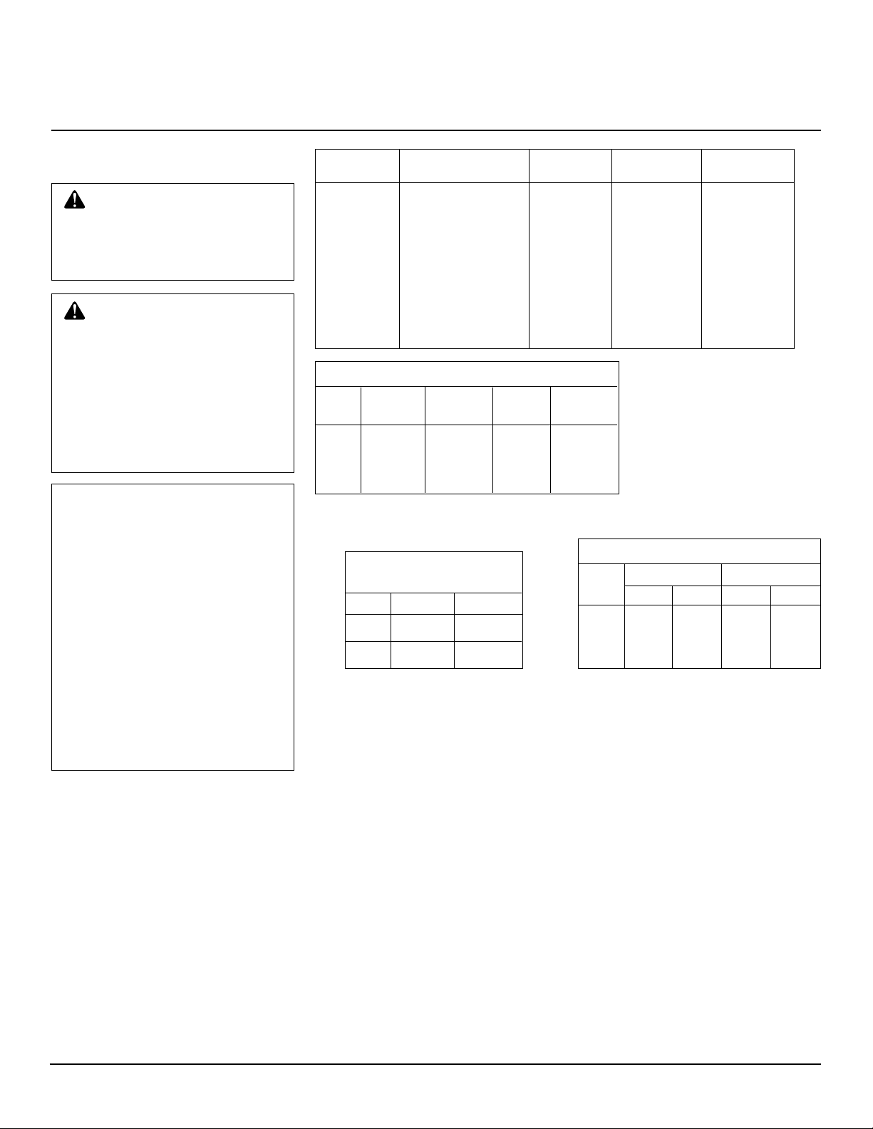
The charts in Figure 4 indicate technical
information regarding the installation of
your gas log set. Please make sure that all of
the specifications shown are applicable be-
fore installation is attempted.
The fireplace must include a working flue
and venting system with the minimum open-
ings shown in the Figure 4.
Continued
MODEL DESCRIPTION
CVSR18 18" Single Burner 50,000 40,000 8" dia.
CPVSR18 18" Single Burner 50,000 40,000 8" dia.
CVSR24 24" Single Burner 60,000 50,000 8" dia.
CPVSR24 24" Single Burner 60,000 50,000 8" dia.
CVDR18 18" Dual Burner 55,000 45,000 8" dia.
CVDR24 24" Dual Burner 65,000 55,000 8" dia.
CVDR30 30" Dual Burner 70,000 60,000 8" dia.
Btu Input
Natural Gas
Btu Input
Propane Gas
Minimum
Vent Opening
MINIMUM FIREBOX SIZES
LOG FRONT BACK
SIZE WIDTH* WIDTH** DEPTH HEIGHT
18" 28" 16" 14" 18"
24" 29
3
/4" 17" 15
1
/2" 18"
30" 36" 27" 18" 18"
*Add 6" if safety valve/pilot is used
**At depth indicated
FUEL INLET PRESSURE
SPECIFICATIONS ("W.C.)
Min. Max.
NG 5.5 10.5
LP 11 13
Figure 4 - Technical Information Charts
VENTING SPECIFICATIONS
FOR INSTALLATION
The fireplace chimney flue and vent must be
drafting properly. To check the vent for
proper drafting: Light a tightly rolled news-
paper on one end and place it at the inside
front edge of the fireplace. Observe the
smoke and be sure the vent is properly
drawing it up the chimney. If the smoke
spills out into the room, extinguish the flame
and remove any obstruction until proper
venting is achieved.
The chimney flue must remain open a mini-
mum of 3" at all times during the operation
of this log set.
BURNER ORIFICE
LOG NATURAL PROPANE/LP
SIZE IN. NUM. IN. NUM.
18" .1285 30 .076 48
24" .144 27 .086 44
30" .154 23 .089 43
8
901048
FOR VENTED NATURAL GAS LOGS
RADCO BURNERS
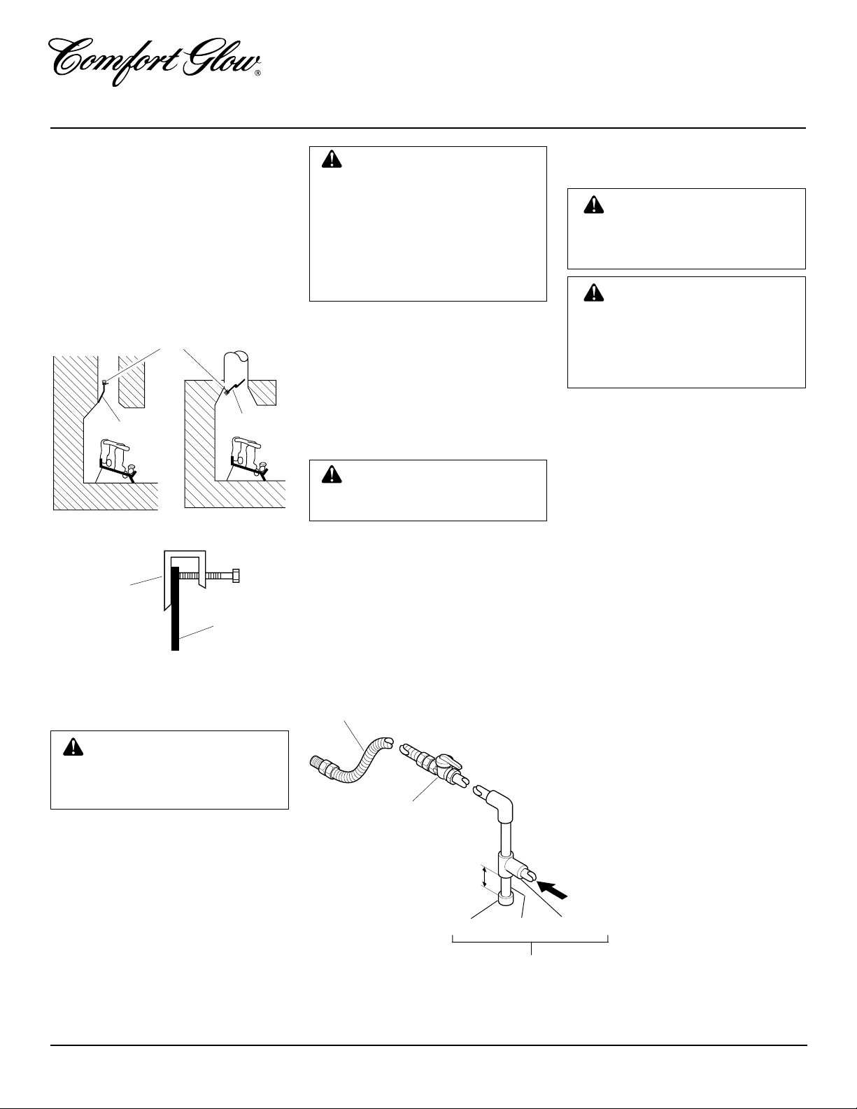
INSTALLING DAMPER
CLAMP
Secure the damper stop clamp provided to
the leading edge of the damper as shown in
Figure 5. If for any reason this clamp doesn't
work on your fireplace, another suitable
clamp or permanent stop must be installed,
or the damper blade must be cut or removed.
Damper Clamp
Damper
Clamp
Damper
Manufactured
Fireplace
Masonry Fireplace
Figure 5 - Attaching Damper Clamp
INSTALLATION
Continued
Damper
Damper
WARNING: Test all gas pip-
ing and connections for leaks
after installing or servicing. Cor-
rect all leaks at once.
WARNING: Never use an
open flame to check for a leak.
Apply a mixture of liquid soap
and water to all joints. Bubbles
forming show a leak. Correct all
leaks at once.
CHECKING GAS
CONNECTIONS
Pressure Testing Gas Supply
Piping System
Test Pressures In Excess Of 1/2 PSIG
1. Disconnect log set and its individual
manual shutoff valve from gas supply
piping system.
2. Cap off open end of gas pipe where
manual shutoff valve was connected.
3. Pressurize supply piping system by either
using compressed air or opening main gas
valve located on or near gas meter.
4. Check all joints of gas supply piping
system. Apply mixture of liquid soap
and water to gas joints. Bubbles form-
ing show a leak.
5. Correct all leaks at once.
6. Reconnect log set and manual shutoff
valve to gas supply . Check reconnected
fittings for leaks.
CONNECTING TO GAS
SUPPLY
WARNING: A qualified ser-
vice person must connect log set
to gas supply. Follow all local
codes.
Installation Items Needed
Before installing log set, make sure you
have the items listed below.
• piping (check local codes)
• sealant (resistant to LP gas)
• manual shutoff valve
• test gauge connection
• adjustable (crescent) wrench or pliers
• sediment trap
• tee joint
• pipe wrench
CAUTION: Use only new,
black iron or steel pipe. Inter-
nally-tinned copper tubing may
be used in certain areas. Check
your local codes. Use pipe of 1/2"
diameter or greater to allow
proper gas volume to log set. If
pipe is too small, undue loss of
pressure will occur.
Install sediment trap in supply line as shown
in Figure 6. Locate sediment trap where it is
within reach for cleaning. Locate sediment
trap where trapped matter is not likely to
freeze. A sediment trap traps moisture and
contaminants. This keeps them from going
into log set controls. If sediment trap is not
installed or is installed wrong, log set may
not run properly.
Installation must include a manual shutoff
valve, union, and plugged 1/8" NPT tap.
Locate NPT tap within reach for test gauge
hook up. NPT tap must be upstream from
log set (see Figure 6).
Apply pipe joint sealant lightly to male
threads. This will prevent excess sealant
from going into pipe. Excess sealant in pipe
could result in a clogged burner injector.
CAUTION: Use pipe joint seal-
ant that is resistant to liquid pe-
troleum (LP) gas.
Figure 9 - Gas Connection
* Purchase the optional A.G.A. design-certified manual shutoff valve from your dealer. See
Accessories, page 20.
** Minimum inlet pressure for purpose of input adjustment.
3" Minimum
Sediment Trap
From Gas Meter (5" W.C.**
to 10.5" W.C. Pressure)
A.G.A. Design-Certified
Manual Shutoff Valve
With 1/8" NPT Tap*
Approved Flexible Gas Hose
(if allowed by local codes)
Tee Joint
Pipe Nipple
Cap
 Loading...