


®
DIRECT-VENT FIREPLACE
OWNER’S OPERATION AND INSTALLATION MANUAL
BHDV37NC, BHDV37PC,
BHDV41NC, AND BHDV41PC
WARNING: If the information in this manual is not followed exactly, a fire or explosion may result causing property damage, personal injury, or loss of life.
FOR YOUR SAFETY
Do not store or use gasoline or other flammable vapors and liquids in the vicinity of this or any other appliance.
FOR YOUR SAFETY
WHAT TO DO IF YOU SMELL GAS
•Do not try to light any appliance.
•Do not touch any electrical switch
•Do not use any phone in your building.
•Immediately call your gas supplier from a neighbor’s phone. Follow the gas supplier’s instructions.
•If you cannot reach your gas supplier, call the fire department.
WARNING: Improper installation, adjustment, alteration, service, or maintenance can cause injury or property damage. Refer to this manual for correct installation and operational procedures. For assistance or additional information consult a qualified installer, service agency, or the gas supplier.
— Installation and service must be performed by a qualified installer, service agency, or the gas supplier.
— This appliance is only for use with the type of gas indicated on the rating plate. This appliance is not convertible for use with other gases, unless a certified kit is used.
This appliance may be installed in an aftermarket* manufactured (mobile) home, where not prohibited by local codes.
* Aftermarket: Completion of sale, not for purpose of resale, from the manufacturer.
Save this manual for future reference.
®
DIRECT-VENT FIREPLACE (NATURAL/PROPANE/LP)
SAFETY INFORMATION
 WARNINGS
IMPORTANT: Read this owner’s manual carefully and completely before trying to assemble, operate, or service this fireplace. Improper use of this fireplace can cause serious injury or death from burns, fire, explosions, electrical shock, and carbon monoxide poisoning.
 DANGER: Carbon monoxide poisoning may lead to death!
This fireplace is a vented product. This fireplace will not produce any gas leakage into your home if properly installed. This fireplace must be properly installed by a qualified service person. The glass door must be properly seated and sealed. If this unit is not properly installed by a qualified service person with glass door properly seated and sealed, gas leakage can occur.
Carbon Monoxide Poisoning: Early signs of carbon monoxide poisoning resemble the flu, with headaches, dizziness, or nausea. If you have these signs, the fireplace may not have been installed properly. Get fresh air at once! Have fireplace inspected and serviced by a qualified service person. Some people are more affected by carbon monoxide than others. These include pregnant women, people with heart or lung disease or anemia, those under the influence of alcohol, and those at high altitudes.
Propane/LP gas and natural gas are both odorless. An odor-making agent is added to each of these gases. The odor helps you detect a gas leak. However, the odor added to these gases can fade. Gas may be present even though no odor exists.
Make certain you read and understand all warnings. Keep this manual for reference. It is your guide to safe and proper operation of this fireplace.
 WARNING: Any change to this fireplace or its controls can be dangerous.
1.This appliance is only for use with the type of gas indicated on the rating plate. This appliance is not convertible for use with other gases unless a certified kit is used.
2.For propane/LP fireplace, do not place propane/LP supply tank(s) inside any structure. Locate propane/LP supply tank(s) outdoors. To prevent performance problems, do not use propane/LP fuel tank of less than 100 lbs. capacity.
3.If you smell gas
•shut off gas supply
•do not try to light any appliance
•do not touch any electrical switch; do not use any phone in your building
•immediately call your gas supplier from a neighbor’s phone. Follow the gas supplier’s instructions
•if you cannot reach you gas supplier, call the fire department.
4.Never install the fireplace
•in a recreational vehicle
•where curtains, furniture, clothing, or other flammable objects are less than 42" from the front, top, or sides of the fireplace
•in high traffic areas
•in windy or drafty areas
5.This fireplace reaches high temperatures. Keep children and adults away from hot surfaces to avoid burns or clothing ignition. Fireplace will remain hot for a time after shut-down. Allow surfaces to cool before touching.
6.Carefully supervise young children when they are in the room with fireplace.
7.Do not modify this fireplace under any circumstances. Any parts removed for servicing must be replaced prior to operating fireplace.
8.Turn fireplace off and let cool before servicing, installing, or repairing. Only a qualified service person should install, service, or repair this fireplace. Have fireplace inspected annually by a qualified service person.
9.You must keep control compartments, burners, and circulating air passages clean. More frequent cleaning may be needed due to excessive lint and dust from carpeting, bedding material, pet hair, etc. Turn off the gas valve and pilot light before cleaning fireplace.
10.Have venting system inspected annually by a qualified service person. If needed, have venting system cleaned or repaired. See Cleaning and Maintenance, page 28.
11.Keep the area around your fireplace clear of combustible materials, gasoline, and other flammable vapor and liquids. Do not run fireplace where these are used or stored. Do not place items such as clothing or decorations on or around fireplace.
12.Do not use this fireplace to cook food or burn paper or other objects.
13.Do not use any solid fuels (wood, coal, paper, cardboard, etc.) in this fireplace. Use only the gas type indicated on fireplace nameplate.
14.This appliance, when installed, must be electrically grounded in accordance with local codes or, in the absence of local codes, with the National Electrical Code, ANS/NFPA 70, or the Canadian Electrical Code, CSA C22.1.
15.Do not obstruct the flow of combustion and ventilation air in any way. Provide adequate clearances around air openings into the combustion chamber along with adequate accessibility clearance for servicing and proper operation.
16.Do not install fireplace directly on carpeting, vinyl tile, or any combustible material other than wood. The fireplace must set on a metal or wood panel extending the full width and depth of the fireplace.
17.Do not use fireplace if any part has been exposed to or under water. Immediately call a qualified service person to arrange for replacement of the unit.
18.Do not operate fireplace if any log is broken.
19.Do not use a blower insert, heat exchanger insert, or other accessory not approved for use with this fireplace.
20.Do not operate fireplace with glass door removed, cracked, or broken.
2 |
106517 |
OWNER’S MANUAL
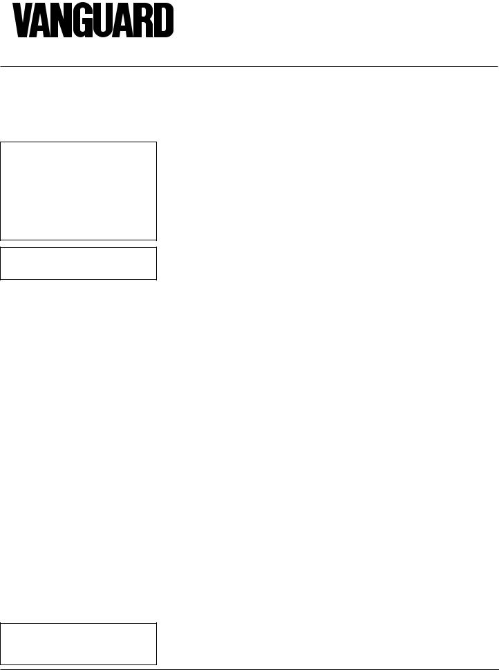
PRODUCT
IDENTIFICATION
Top Louver |
Vent Opening |
|
Panel |
||
|
||
Nailing |
Stand-off |
|
Flange |
|
Glass Door
Assembly
Blower Adjustment
(Optional Installation)
Log Set
Pilot Assembly
Burner
Piezo Ignitor
Valve |
Grate Assembly |
|
|
||
Glowing Embers |
|
|
Lower Louver |
Lava Rock |
|
Panel |
||
|
Figure 1 - Vanguard Direct-Vent Fireplace BHDV Series
GLOSSARY OF
TERMS
Chase - A box-like enclosure to protect venting from the elements when the venting run is on the outside of a structure.
Mastic - A pliable sealent for use around the vent terminal.
Snorkel Termination - A box that raises the horizontal termination above ground level clearances.
Vent Terminal - Mounted on an outside wall or roof to separate the inlet and outlet of the vent system and protect it from weather.
Vinyl Siding Standoff - A metal box that separates the vent cap from vinyl siding.
Wall Thimble/Firestop - A metal plate used to secure the vent pipe when it passes through a wall or ceiling.
LOCAL CODES
Install and use fireplace with care. Follow all local codes. In the absence to local codes, use the current National Fuel Gas Code ANS Z223.1, also known as NFPA 54* (USA) or the current CAN/CGA-B149[.1 or
.2] Installation Codes (Canada).
*Available from:
American National Standards Institute, Inc.
1430 Broadway
New York, NY 10018
National Fire Protection Association, Inc.
Batterymarch Park
Quincy, MA 02269
PRODUCT
FEATURES
OPERATION
This direct-vent fireplace is clean burning and vents easily through outside walls or vertically using outside air for combustion. Heat is generated by both realistic flames and glowing embers. When used without the blower accessory, the fireplace requires no electricity making it ideal for emergency backup heat.
PIEZO IGNITOR
This fireplace has a piezo ignitor. This system requires no matches, batteries, or other sources to light fireplace.
106517 |
3 |
®
DIRECT-VENT FIREPLACE (NATURAL/PROPANE/LP)
PRE-INSTALLATION PREPARATION
CLEARANCES
Minimum clearances to combustibles for the fireplace are as follows:
Must maintain a minimum 1" clearance to combustibles
LOCATION AND SPACE REQUIREMENTS
Determine the safest and most efficient location for your Vanguard direct-vent fireplace. Make sure that rafters and wall studs are not in the way of the venting system. Choose a location where the heat output is not affected by drafts, air conditioning ducts, windows or doors. Figure 2 shows some common locations. Read all venting information in this manual. Be aware of all restrictions and precautions before deciding the exact location for your fireplace.
When deciding the location of your fireplace, follow these rules:
1.Do not connect this fireplace to a chimney flue serving a separate solid-fuel burning fireplace or appliance.
2.Due to high temperatures, do not locate this fireplace in high traffic areas or near furniture or draperies.
3.Proper clearances must be maintained.
4.If your fireplace is to be installed directly on carpeting, vinyl tile, or any combustible material other than wood, it must be installed on a metal or wood panel extending the full width and depth of the fireplace. See Figure 3.
Flush with a wall
Through exterior wall enclosed in a chase
Corner installation
Figure 2 - Common Fireplace Locations
RW
D
FW
Fireplace size |
D x FW x RW |
||
37" |
18 1/2" |
37" |
14" |
41" |
18 1/2" |
41" |
18" |
Figure 3 - Fireplace Bottom Dimensions
Back, and sides |
0"/mm |
Perpendicular walls |
6" (152mm) |
Floor |
0"/mm |
Ceiling to louver opening |
42" (1067mm) |
Front |
36" (914mm) |
Top of Standoffs |
0"/mm |
See General Venting on page 5 for specific venting clearances.
FRAMING AND FINISHING
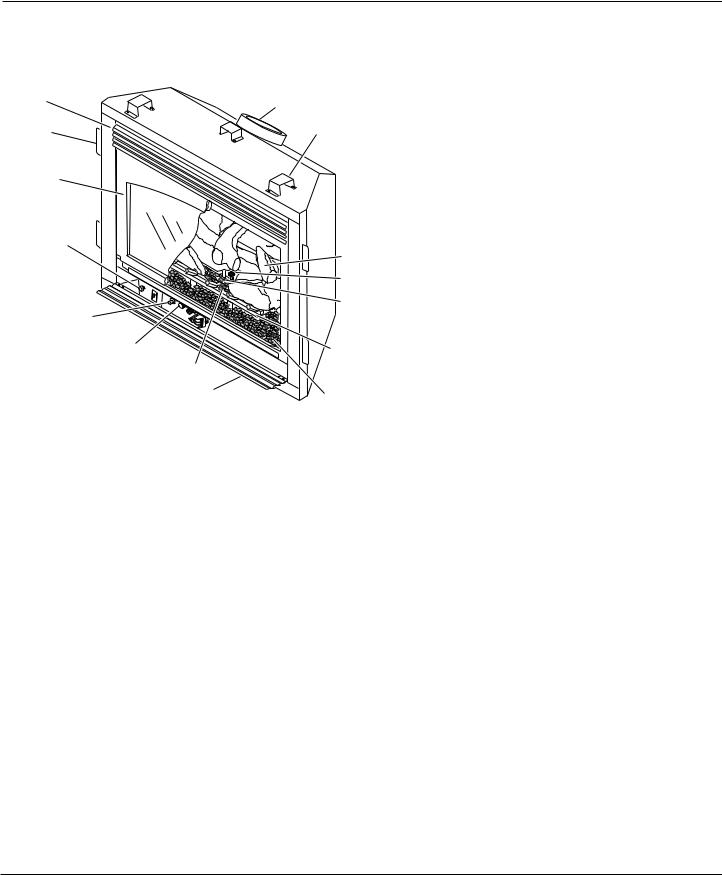
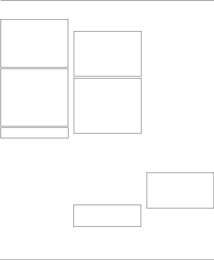
Figures 4 and 5 show typical framing of this fireplace. Figure 6 on page 5 shows framing for corner installation. All minimum clearances must be met. Do not install fireplace directly on carpeting, vinyl tile, or any combustible material other than wood. The fireplace must set on a metal or wood panel extending the full width and depth of the fireplace.
See Accessories on pages 38 and 39 for mantel kits available for this fireplace. If you are using a separate combustible mantel piece, refer to Figure 7 on page 5 for proper installation height. You can install noncombustible mantels at any height above the fireplace.
34 3/4"
36 3/4"
37 1/2"
41 1/2"
(37) 34 3/4"
(41) 36 3/4"
20"
5/8" for drywall facing
Figure 5 - Framing Clearances for Typical Fireplace Installation
20" Vertical Termination
19" Horizontal Termination
Note: Where two numbers are given the top number is exclusive to the
37" Fireplace and the bottom number is exclusive to the 41" Fireplace
Figure 4 - Framing Clearances for Installation Against an Exterior Wall
4 |
106517 |
|
|
|
|
|
|
|
|
|
|
OWNER’S MANUAL |
||
PRE-INSTALLATION |
|
|
|
|
|
|
GENERAL VENTING |
|
||||
PREPARATION |
|
|
|
|
|
|
|
These models are approved for use with |
||||
|
|
|
|
|
|
|
Simpson Dura-Vent 6 5/8" direct-vent pipe |
|||||
Continued |
|
|
|
|
|
|
|
components and terminations as well as both |
||||
|
|
|
|
|
|
|
|
|
|
|
||
|
|
|
|
|
|
|
|
|
|
|
flex and rigid Vanguard vent components. |
|
|
|
|
|
|
|
|
|
|
|
|
Your fireplace is approved to be vented either |
|
13" |
|
|
9 1/4" |
41" |
|
|
|
through the side wall, or vertically using the |
||||
|
|
|
|
|
following guidelines: |
|||||||
|
|
|
|
|
|
|
|
|
|
|
||
29" |
|
|
|
|
|
|
|
|
|
|
• Only use Vanguard or Simpson Dura- |
|
|
|
|
|
|
|
|
|
|
|
|
||
|
|
|
|
|
|
|
|
|
|
|
Vent GS venting components or kits spe- |
|
|
|
|
|
|
|
|
|
|
|
|
cifically approved for this fireplace. |
|
|
|
|
|
|
|
|
|
|
|
|
• Minimum clearance between vent pipes |
|
|
|
|
|
|
|
|
|
|
|
|
and combustible materials is 1" (25 mm), |
|
|
|
|
|
|
|
|
|
|
|
|
||
|
10 1/4" |
|
|
|
|
|
|
|
|
|
except where stated otherwise. |
|
|
|
|
|
|
|
|
|
|
|
|||
|
|
|
|
|
|
|
|
|
|
• Combustible material may be flush with |
||
|
8 3/4" |
|
|
37" |
|
|
|
|
|
|
||
|
|
|
|
|
|
|
|
|
the top front of fireplace with a maxi- |
|||
|
|
|
|
41" |
|
|
|
|
|
|
||
|
|
|
|
|
|
|
|
|
|
mum thichness of 3/4". |
||
|
|
|
|
37 1/2" |
|
|
|
|
|
Nailing Tabs |
||
|
|
|
|
|
|
|
|
|
• Do not recess venting terminals into a |
|||
|
|
|
|
41 1/2" |
|
|
|
|
|
|
||
|
|
|
|
|
|
|
|
|
|
|||
|
|
|
|
|
|
|
|
|
|
wall or siding. |
||
|
|
|
|
|
|
|
|
|
|
|
||
|
|
|
|
58" |
|
|
|
|
|
|
• You must install a vinyl siding standoff if |
|
|
|
|
|
|
|
|
|
|
|
|||
Note: Where two numbers are given the top number |
|
|
|
|
|
|
vinyl siding is covering the exterior wall. |
|||||
|
|
|
|
|
|
• Install horizontal venting with a 1/4" rise |
||||||
is exclusive to the 37" Fireplace and the bottom |
|
|
|
|
|
|
||||||
number is exclusive to the 41" Fireplace |
|
|
|
|
|
|
for every 12" of run toward the termi- |
|||||
Figure 6 - Framing Clearances for Corner Installation |
|
|
|
|
|
|
nation. |
|||||
|
|
|
|
|
|
|
|
|||||
|
|
|
|
|
|
|
|
|
|
1 |
|
|
|
|
|
|
|
|
|
|
|
|
2 |
|
|
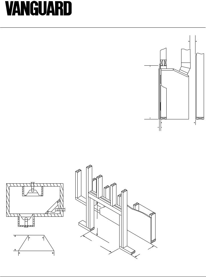
Note: There must be a |
|
|
|
|
|
|
3 |
|
|
|||
A |
|
|
|
|
|
|||||||
minimum clearance of |
|
|
|
|
Wall |
|||||||
|
|
|
|
|
|
4 |
|
|||||
18" above top of louver |
|
|
|
|
|
|
|
|
||||
|
|
|
|
|
|
|
|
|
||||
opening when install- |
|
B |
|
|
5 |
|
|
|||||
ing a television or |
|
|
|
|
|
|||||||
|
|
|
|
|
|
|
|
|
||||
entertainment center |
|
|
|
|
C |
6 |
|
|
||||
above the fireplace. |
|
|
|
|
|
|
|
|
||||
|
|
|
|
|
D |
|
|
|
||||
|
|
|
|
|
|
|
|
|
E |
7 |
|
|
|
|
|
|
|
|
|
|
|
|
|||
|
|
|
|
|
|
|
|
|
|
|
|
|
|
|
|
|
|
|
|
|
|
F |
G |
|
|
|
|
|
|
|
|
|
|
|
|
|
|
|
|
|
|
|
|
|
|
|
|
Top of Louver Opening |
|||
|
|
|
|
|
|
|
|
|
|
|||
|
Ref. |
Mantel Depth |
|
Ref. |
|
Mantel from Top |
|
|
|
|||
|
|
|
|
|
|
|
|
of Louver Opening |
|
|
|
|
|
|
|
|
|
|
|
|
|
|
|||
|
1 |
14" (356mm) |
|
A |
|
16" (406mm) |
|
|
|
|||
|
|
|
|
|
|
|
|
|
|
|||
|
2 |
12" (305mm) |
|
B |
|
14" (356mm) |
|
|
|
|||
|
3 |
10" (254mm) |
|
C |
|
12" (305mm) |
|
|
|
|||
|
|
|
|
|
|
|
|
|
|
|||
|
4 |
8" (203mm) |
|
D |
|
10" (254mm) |
|
|
|
|||
|
|
|
|
|
|
|
|
|
|
|||
|
5 |
6" (152mm) |
|
E |
|
8" (203mm) |
|
|
|
|||
|
|
|
|
|
|
|
|
|
|
|||
|
6 |
4" (101mm) |
|
F |
|
6" (152mm) |
|
|
|
|||
|
|
|
|
|
|
|
|
|
|
|||
|
7 |
2" (51mm) |
|
G |
|
4" (101mm) |
|
|
|
|||
|
|
|
|
|
|
|
|
|
|
|
|
|
•You may paint the vent terminal with 450ºF (232ºC) heat-resistant paint to coordinate with the exterior finish.
•There must not be any obstruction such
as bushes, garden sheds, fences, decks, or utility buildings within 24" from the front of the termination cap.
• Do not locate termination cap where excessive snow or ice build up may occur. Be sure to clear vent termination area after snow falls to prevent accidental blockage of venting system. When using snow blowers, do not direct snow towards vent termination area.
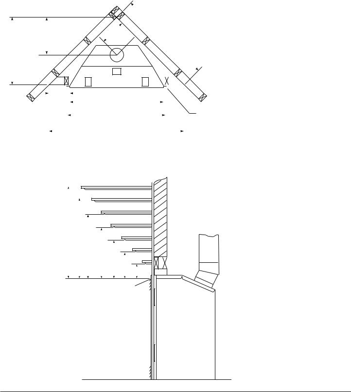
LOCATION OF VENT
TERMINATION
When locating vent termination, it is important to observe the minimum clearances shown in Figure 8, page 6. You will avoid extra framing by positioning your fireplace against an already existing framing member. The sides of the fireplace may be positioned directly against combustible walls.
*Check with local codes or with the current
CAN/CGA B149[.1 or .2] Installation Codes for Canada or the USA Installations follow the current National Fuel Gas Code, ANS Z223.1, also known as NFPA 54.
Figure 7 - Clearances for Combustible Mantels |
Continued |
106517 |
5 |

®
DIRECT-VENT FIREPLACE (NATURAL/PROPANE/LP)
GENERAL VENTING Continued
D |
H |
V |
E |
|
|
|
B |
L |
C |
|
|
Fixed |
V |
|
B |
V |
|
Closed |
Openable |
Fixed |
|
|
|
Openable |
|
|
Closed |
|
F |
|
|
|
B |
|
V |
|
|
|
|
B |
V J |
X |
G |
|
|
|
|
|
B |
|
A |
|
|
|
|
|
|
|
V TERMINATION CAP |
X AIR SUPPLY INLET |
G GAS METER |
||
 N
N 
N
I
|
G |
|
V |
M |
G |
V K X |
V |
|
A |
RESTRICTED AREA  (TERMINATION PROHIBITED)
A= clearance above grade, veranda, porch, deck, or balcony [*12 inches (305mm) minimum]
B= clearance to window or door that may be opened
[12 inches (305mm) minimum]
C = clearance to permanently closed window [minimum 12 inches (305mm) recommended to prevent condensation on window]
D = vertical clearance to ventilated soffit located above the terminal within a horizontal distance of 24 inches (610mm) from the center-line of the terminal [18 inches (457mm) minimum]
E= clearance to unventilated soffit [12 inches (305mm) minimum]
F= clearance to outside corner (see below)
G= clearance to inside corner (see below)
H= *not to be installed above a meter/regulator assembly within
36 inches (914mm) horizontally from the center-line of the regulator
I= clearance to service regulator vent outlet [*72 inches (1829mm) minimum]
J= clearance to non-mechanical air supply inlet to building or the combustion air inlet to any other fireplace [*12 inches (305mm) minimum]
K= clearance to a mechanical air supply inlet [*72 inches (1829mm) minimum]
L= † clearance above paved side-walk or a paved driveway located on public property [*84 inches (2133mm) minimum]
M= clearance under veranda, porch, deck [*12 inches (305mm) minimum ‡]
N= clearance above a roof shall extend a minimum of 24 inches (610mm) above the highest point when it passes through the roof surface and any other obstruction within a horizontal distance of 18 inches (457mm)
† vent shall not terminate directly above a side-walk or paved driveway which is located between two single family dwellings and serves both dwellings*
‡ only permitted if veranda, porch, deck or balconey is fully open on a minimum of 2 sides beneath the floor*
* as specified in CAN/SGA B149 (.1 or .2) Installation Codes (1991) for Canada or for U.S.A. installation follow the current National Fuel Gas Code, ANS Z223.1
Note: Local codes or regulations may require different clearances
Termination Clearances for Buildings with Combustible and Noncombustible Exteriors
Inside Corner |
Outside Corner |
Recessed Location |
|
|
|
D |
|
|
|
C |
C |
A |
A = 6" (152mm) |
|
E |
|
|
|
|
V |
V |
V |
|
|
B |
B = 6" (152mm) |
|
Balcony with No Side Wall
G |
V |
G = Combustible 24" (610mm)
Noncombustible 18" (457mm)
Balcony with Perpendicular Side Wall
H
V

 J
J 
Combustible &
Noncombustible
H = 24" (610mm)
J = 20" (508mm)
C = Maximum depth of 48" (1219mm) for recessed location
D = Minimum width for back wall of recessed location - Combustible - 38" (965mm) Noncombustible - 24" (610mm)
E = Clearance from corner in recessed locationCombustible - 6" (152mm) Noncombustible - 2" (51mm)
Figure 8 - Minimum Clearances for Vent Terminations
6 |
106517 |
OWNER’S MANUAL
VENTING INSTALLATION
 WARNING: Read all instructions completely and thoroughly before attempting installation. Failure to do so could result in serious injury, property damage or loss of life. Operation of improperly installed and maintained venting system could result in serious injury, property damage or loss of life.
 WARNING: Seal all vent connections. Seal only the outer pipe connectionswithhightemperature silicone(600°F/316°C).Beforejoining elbows and pipes, apply a bead of high temperature silicone sealant(GERTV106/LoctiteRTV81585) to the male end of the elbow or pipe. High temperature silicone must also be used to re-seal any connections after maintenance to venting system.
NOTICE: Failure to follow these instructions will void the warranty.
INSTALLATION
PRECAUTIONS
Consult local building codes before beginning the installation. The installer must make sure to select the proper vent system for installation. Before installing vent kit, the installer must read this fireplace manual and vent kit instructions.
Only a qualified service person should install venting system. The installer must follow these safety rules:
•Wear gloves and safety glasses for protection
•Use extreme caution when using ladders or when on roof tops
•Be aware of electrical wiring locations in walls and ceilings
The following actions will void the warranty on your venting system:
•Installation of any damaged venting component
•Unauthorized modification of the venting system
•Installation of any component part not manufactured or approved by DESA International
•Installation other than as instructed by these instructions
 WARNING: This gas fireplace and vent assembly must be vented directly to the outside. The venting system must NEVER be attached to a chimney serving a separate solid fuel burning appliance. Each gas appliance must use a separate vent system. Do not use common vent systems.
 WARNING: Horizontal sections of this vent system require a minimum clearance of 2" from the top of the pipe and 1" minimum to the sides and bottom. 1 1/2" clearance is required where the termination penetrates a combustible wall. Vertical sections of this system require a minimum of 1" clearance to combustible materials on all sides of the pipe.
INSTALLATION PLANNING
There are two basic types of direct-vent installation:
•Horizontal Termination
•Vertical Termination
It is important to select the proper length of vent pipe for the type of termination you choose. It is also important to note the wall thickness.
For Horizontal Termination: Select the amount of vertical rise desired. The horizontal run of venting must have 1/4" rise for every 12" of run towards the termination.
 WARNING: Never run the vent downward as this may cause excessive temperatures which could cause a fire.
You may use one or two 90° elbows in this vent configuration. See Horizontal Termination Configurations on pages 10 and 11.
For Vertical Termination: Measure the distance from the fireplace flue outlet to the ceiling. Add the ceiling thickness, the verti-
cal rise in an attic or second story, and allow for sufficient vent height above the roofline. You may use one or two 90° elbows in this vent configuration. See Vertical Termination Configurations on pages 13 and 14.
Note: You may use two 45° elbows in place of a 90° elbow. You must follow rise to run ratios when using 45° elbows.
For two-story applications, firestops are required at each floor level. If an offset is needed in the attic, additional pipe and elbows will be required.
You may use a chase with a vent termination with exposed pipe on the exterior of the house. See Installing Vent System in a Chase, below.
Your Vanguard direct-vent fireplace has been tested for a minimum 3' rise with a maximum 10" wall thickness. The maximum horizontal run is 20' with 8' vertical rise (see Installation for Horizontal Termination, page 8). The maximum vertical run is 30' (seeInstallation for Vertical Termination, page 12).
It is very important that the venting system maintain its balance between the combustion air intake and the flue gas exhaust. Certain limitations apply to vent configurations and must be strictly followed.
Installing Vent System in a Chase
A chase is a vertical box-like structure built to enclose venting that runs along the outside of a building. A chase is not required for such venting.
NOTICE: Treatment of firestops and construction of the chase may vary from building type to building type. These instructions are not substitutes for the requirements of local building codes. You must follow all local building codes.
Note: When installing in a chase, you should insulate the chase as you would the outside walls of your home. This is especially important in cold climates. Minimum clearance between vent pipes and combustible materials such as insulation is 1".
After framing the chase (see Framing and Finishing on page 4) install the vent system by following the installation instructions.
Continued
106517 |
7 |
®
DIRECT-VENT FIREPLACE (NATURAL/PROPANE/LP)
VENTING INSTALLATION
Continued
INSTALLATION FOR HORIZONTAL TERMINATION
1.Determine the route your horizontal venting will take. Note: The location of the horizontal vent termination on the exterior wall must meet all local and national building codes and must not be easily blocked or obstructed.
 WARNING: Do not recess vent terminal into a wall or siding.
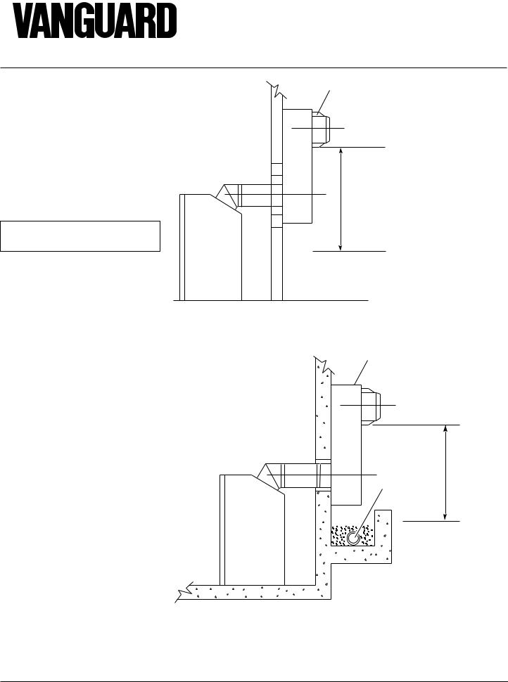
Snorkel terminations are available for terminations requiring a vertical rise on the exterior of the building (see Figures 9 and 10). Snorkel kit SVK is also available (see page 15). Follow the same installation procedures used for standard horizontal terminations. If installing the snorkel termination below grade (basement applications), you must provide proper drainage to prevent water from entering the snorkel termination (see Figure 10). Do not back fill around the snorkel termination.
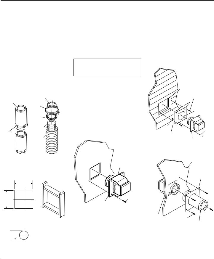
2.Rigid vent pipes and fittings have special twist-lock connections. Assemble the desired combination of pipe and elbows to the appliance adaptor with pipe seams oriented towards the wall or floor.
Twist-lock Procedure: The female ends of the pipes and fittings have four locking lugs (indentations). These lugs will slide straight into matching slots on the male ends of adjacent pipes and fittings. (All connections must be sealed with high temperature silicone sealant as specified in the second warning statement on page 7.) Push the pipe sections together and twist one section clockwise approximately one-quarter turn until the sections are fully locked. See Figure 11, page 9. Note: Horizontal runs of vent must be supported every three feet. Use wall straps for this purpose.
Flexible vent pipe must be installed with spacer springs every 12". See Figure 11, page 9.All connections must be clamped tightly and sealed with high temperature silicone sealant as specified in the second warning statement on page 7.
Snorkel |
12" Minimum |
Figure 9 - Snorkel Termination
Snorkel
12" Minimum
Adequate drainage
Figure 10 - Snorkel Termination with Drainage Pipe
8 |
106517 |
OWNER’S MANUAL
VENTING INSTALLATION
Continued
3.Attach vent pipe assembly to the fireplace. Set fireplace in front of it’s permanent location to insure minimum clearances. Mark the wall for a 10" square hole (for noncombustible material such as masonry block or concrete, a 7 1/2" diameter hole is acceptable). See Figure 12. The center of the hole should line up with the centerline of the horizontal rigid vent pipe. Cut a 10"x10" (254mm x 254mm) square hole through combustible exterior wall (7 1/2" [190mm] diameter hole if noncombustible). Frame as necessary (see Figure 12).
|
4" Clamp |
|
Female |
7" Clamp |
|
Locking |
||
|
||
Lugs |
|
|
|
Spacer |
|
|
Spring |
|
Male |
4" Flex |
|
Pipe |
||
Slots |
||
|
||
|
7" Flex |
|
|
Pipe |
|
Rigid Vent Pipe Flexible Vent Pipe |
||
Figure 11 - Vent Pipe Connections
Vent Opening
Combustible Wall
10"
(254mm)
10"
(254mm)
(Framing
Detail)
Vent Opening
Noncombustible Wall
7 1/2"  (190mm)
Figure 12 - Vent Opening Requirements
4.Apply a bead of non-hardening mastic around the outside edge of the vent cap. Position the vent cap in the center of the 7 1/2" or 10" hole on the exterior wall with the arrow on the vent cap pointing up. Insure proper clearance of 1" to combustibles is maintained. Attach the vent cap with four wood screws supplied (see Figure 13). Note: Replace the wood screws with appropriate fasteners for stucco, brick, concrete, or other types of siding.
 WARNING: Do not recess vent termination in to any wall. This will cause a fire hazard.
For vinyl siding use vinyl siding standoffs between vent cap and exterior wall. The vinyl siding standoff prevents excessive heat from melting the vinyl siding material. Bolt the vent cap to the standoff. Apply non-hardening mastic around outside edge of the standoff instead of the vent cap assembly. Use wood screws provided to attach the standoff. See Figure 14.
5.Slide the wall thimble over the vent pipe before connecting the horizontal run to the vent cap (see Figure 15).
Apply Mastic to All Four Sides
UP
Wood
Screw
Vent Cap
Figure 13 - Installing Horizontal Vent Cap
6.Carefully move the fireplace with vent assembly attached toward the wall and insert the vent pipe into the horizontal termination. The pipe overlap should be a minimum of 1 1/4". Apply silicone to the outer pipe connection. Fasten all vent connections with screws provided. Refer to Fireplace Installation on page 16 for instructions on securing unit to framing or floor.
7.Slide the wall thimble against the interior wall surface and attach with screws provided (see Figure 15).
Cut Vinyl Siding
Away to Fit
Standoff
Wood Screw
Standoff
UP
Nut

 Bolt Apply Mastic
to All Four Sides Vent Cap
Figure 14 - Installing Vinyl Siding Standoff
Interior Wall
Surface
Wall
Thimble
Vent Cap
(Horizontal |
Screw |
|
|
Termination) |
Horizontal |
|
Vent Pipe |
Figure 15 - Connecting Vent Cap with Horizontal Vent Pipe
Continued
106517 |
9 |
®
DIRECT-VENT FIREPLACE (NATURAL/PROPANE/LP)
VENTING INSTALLATION
Continued
Horizontal Termination
Configurations
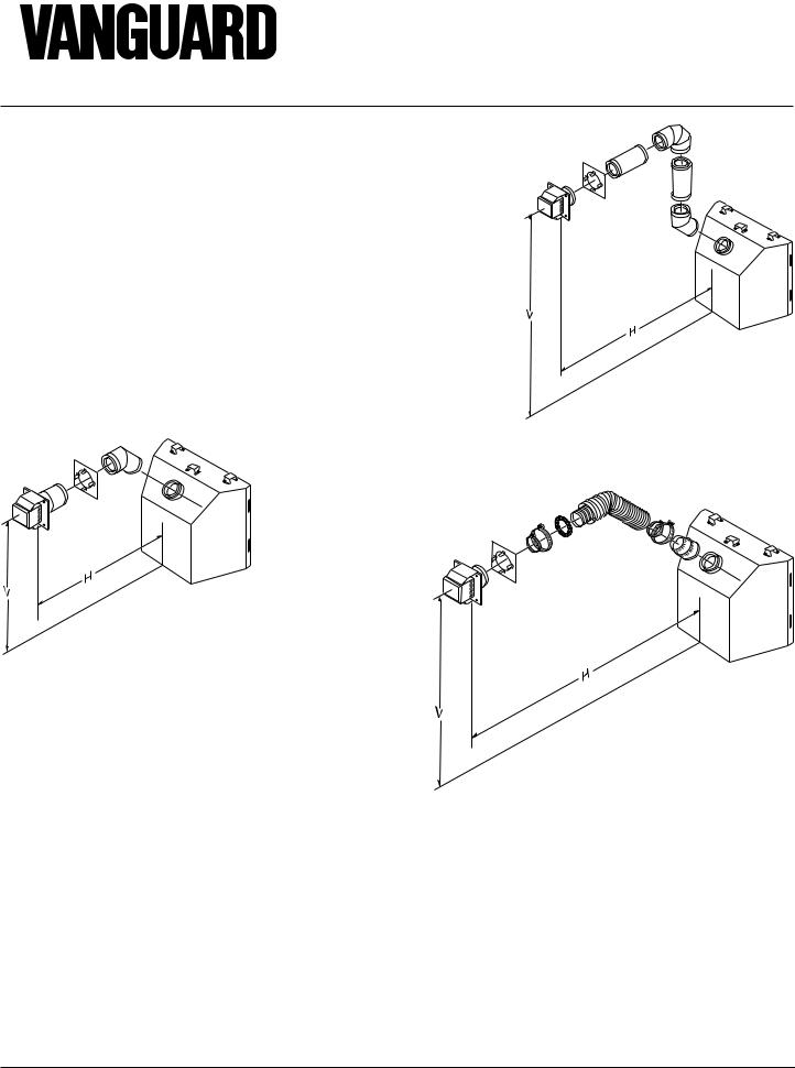
Figures 16 through 20 show different configurations for venting with horizontal termination. Each figure includes a chart with vertical minimum/maximum and horizontal maximum dimensions which must be met. Seal all connections with high temperature silicone sealant (outer pipe only) as specified in the second warning statement on page 7. All horizontal terminations require 1/4" rise per 12" of horizontal run.
UP
BGFVK Vent Kit Shown (recommended for use with cabinet mantels)
Horizontal Venting
Vertical (V) |
Horizontal (H) |
37" min. |
10" max. |
Figure 16 - Horizontal Termination Configuration for Rigid Venting
Horizontal Venting
|
UP |
Vertical (V) |
Horizontal (H) |
44" min. |
29" max. |
(30° and 90° only, no vertical pipe) |
|
55" min. |
41" max. |
(30° elbow, 1' vertical pipe, 90° elbow) |
|
67" min. |
60" max. |
79" min. |
84" max. |
96" min. |
20' max. |
Note: This configuration for use with |
|
corner installation. |
BVK Vent Kit Shown |
Figure 17 - Horizontal Termination Configuration for Rigid Venting Using One 90° Elbow
Horizontal Venting
See information in
Figure 18 for
Vertical(V) and
Horizontal(H) |
UP |
|
|
maximums and |
|
minimums. The |
|
same amounts |
|
apply for flexible |
|
venting. |
|
Note: Figure 17 |
BFGFVK and FGFVK |
applies to rigid |
Vent Kits Shown |
|
|
venting only. |
|
Figure 18 - Horizontal Termination Using Flexible Venting
10 |
106517 |
OWNER’S MANUAL
VENTING
INSTALLATION
Continued
Venting with Two 90° Elbows
Vertical (V) |
Horizontal (H1) |
Horizontal (H1) + |
|
|
Horizontal (H2) |
5' min. |
2' max. |
6' max. |
6' min. |
4' max. |
12' max. |
7' min. |
6' max. |
18' max. |
8' min. |
8' min. |
20' max. |
20' max. |
8' max. |
20' max. |
UP
Figure 19 - Horizontal Termination Configuration for Rigid Venting Using Two 90° Elbows
Venting with Two 90° Elbows
Vertical (V) |
Horizontal (H1) + |
|
Horizontal (H2) |
5' min. |
6' max. |
6' min. |
12' max. |
7' min. |
18' max. |
8' min. |
20' max. |
20' max. |
20' max. |
Figure 20 - Horizontal Termination Configuration for Rigid Venting Using Two 90° Elbows with Termination at 90° with Fireplace
Continued
106517 |
11 |
®
DIRECT-VENT FIREPLACE (NATURAL/PROPANE/LP)
VENTING INSTALLATION
Continued
INSTALLATION FOR VERTICAL TERMINATION
NOTICE: Use rigid pipe only. Flex venting is not to be used with a vertical termination.
1.Determine the route your vertical venting will take. If ceiling joists, roof rafters, or other framing will obstruct the venting system, consider an offset (see Figure 21) to avoid cutting loadbearing members. Note: Pay special attention to these installation instructions for required clearances (air space) to combustibles when passing through ceilings, walls, roofs, enclosures, attic rafters, etc. Do not pack air spaces with insulation. Also note maximum vertical rise of the venting system and any maximum horizontal offset limitations. Offsets must fall within the parameters shown in Figure 8 on page 6.
2.Set the fireplace in desired location. Drop a plumb line down from the ceiling to the position of the fireplace exit flue. Mark the center point where the vent will penetrate the ceiling. Drill a small locating hole at this point.
Drop a plumb line from the inside of the roof to the locating hole in the ceiling. Mark the center point where the vent will penetrate the roof. Drill a small locating hole at this point.
Roof
Flashing
Wall Strap
45° Elbow
Ceiling Firestop
Figure 21 - Offset with Wall Strap and 45°
Elbows
Flat Ceiling Installation
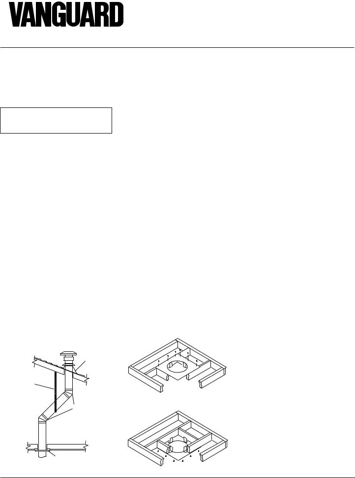
1.Cut a 10" square hole in the ceiling using the locating hole as a center point. The opening should be framed to 10"x10" (254mm x 254mm) inside dimensions, as shown in Figure 12 on page 9 using framing lumber the same size as the ceiling joists. If the area above the ceiling is an insulated ceiling or a room, nail firestop from the top side. This prevents loose insulation from falling into the required clearance space. Otherwise, install firestop below the framed hole. The firestop should be installed with no less than three nails per side (see Figure 22).
2.Assemble the desired lengths of pipe and elbows necessary to reach from the fireplace flue up through the firestop. All connections must be sealed with high temperature silicone sealant as specified in the second warning statement on page 7. Be sure all pipe and elbow connections are fully twistlocked (see Figure 11, page 9).
3.Cut a hole in the roof using the locating hole as a center point. (Cover any exposed open vent pipes before cutting hole in roof.) The 10"x10" hole must be measured on the horizontal; actual length may be larger depending on the pitch of the roof. There must be a 1" clearance from the vent pipe to combustible materials. Frame the opening as shown in Figure 12 on page 9.
If area above is a room, install firestop above framed hole.
If area above is not a room, install firestop below framed hole.
Figure 22 - Installing Firestop
4.Connect a section of pipe and extend up through the hole.
Note: If an offset is needed to avoid obstructions, you must support the vent pipe every 3 feet. Use wall straps for
this purpose (see Figure 21). Whenever possible, use 45° elbows instead of 90° elbows. The 45° elbow offers less restriction to the flow of the flue gases and intake air.
5.Place the flashing over the pipe section(s) extending through the roof. Secure the base of the flashing to the roof and framing with roofing nails. Be sure roofing material overlaps the top edge of the flashing as shown in Figure 21. There must be a 1" clearance from the vent pipe to combustible materials.
6.Continue to add pipe sections until the height of the vent cap meets the minimum building code requirements described in Figure 8 on page 6. Note: You must increase vent height for steep roof pitches. Nearby trees, adjoining rooflines, steep pitched roofs, and other similar factors may cause poor draft or down-draft- ing in high winds. Increasing the vent height may solve this problem.
7.Twist-lock the vent cap onto the last section of vent pipe and seal outer pipe connection with high temperature silicone sealant as specified in the second warning statement on page 7.
Note: If the vent pipe passes through any occupied areas above the first floor, including storage spaces and closets, you must enclose pipe. You may frame and sheetrock the enclosurewithstandardconstructionmaterial.Make sure and meet the minimum allowable clearances to combustibles. Do not fill any of the required air spaces with insulation.
Cathedral Ceiling Installation
1.Remove shingles or other roof covering as necessary to cut the rectangular hole for the support box. Mark the outline of the cathedral ceiling support box on the roof sheathing using the locating hole as a center point.
2.Cut the hole 1/8" larger than the support box outline (see Figure 23, page 13).
12 |
106517 |
 Loading...