


160-IF
Table of contents
 Loading...
Save this manual for future reference.
For more information, visit www.desatech.com
IMPORTANT: Read and understand this manual before
assembling, starting or servicing heater.
Improper use of heater can cause serious injury. Keep
this manual for future reference.
VENTED PORTABLE FORCED AIR HEATER
OWNER’S MANUAL
MODELS: 160-IF, 280-IF
TABLE OF CONTENTS
Safety Information ............................................... 2
Unpacking .......................................................... 3
Product identification ........................................... 3
Fuels .................................................................... 4
To Start Heater ....................................................
4
To
Stop Heater .................................................... 4
Thermostat Operation ......................................... 4
Moving and Transporting Heater ......................... 4
Preventative Maintenance ................................... 5
Troubleshooting ................................................... 5
Diagrams ............................................................. 7
Illustrated Parts Breakdown and Parts List ....... 10
Specifications ....................................................
15
Technical Service ..............................................
15
Accessories ....................................................... 15
Warranty and Repair Service ............................ 16
www.desatech.com
114909-01A
2
SAFETY INFORMATION
WARNING: This product con-
tains and/or generates chemicals
known to the State of California
to cause cancer or birth defects
or other reproductive harm.
IMPORTANT: Read this owner’s
manual carefully and completely
before trying to assemble,
operate or service this heater.
Improper use of this heater can
cause serious injury or death
from burns, fire, explosion,
electrical shock and carbon
monoxide poisoning.
DANGER: Carbon monoxide
poisoning may lead to death!
Carbon Monoxide Poisoning: Early signs of carbon
monoxide poisoning resemble the flue, with head
-
aches, dizziness and/or nausea. If you have these
signs, the heater may not be working properly. Get
fresh air at once! Have heater serviced. Some people
are more affected by carbon monoxide than others.
These include pregnant women, persons with heart
or lung disease or anemia, those under the influence
of alcohol and those at high altitudes.
Make certain you read and understand all warn-
ings. Keep this manual for reference. It is your
guide to safe and proper operation of this heater.
1. Use only kerosene, #1#2 diesel/fuel oil, JET A
or JP-8 fuels to avoid risk of fire or explosion.
Never use gasoline, naphtha, paint thinners,
alcohol or other highly flammable fuels.
2. Fueling
a) Personnel involved with fueling shall be
qualified and thoroughly familiar with the
manufacturerʼs instructions and applicable
regulations regarding the safe fueling of
heating units.
b) Only the type of fuel specified on the
heaterʼs data plate shall be used.
c) All flame, including the pilot light, if any,
shall be extinguished and the heater al
-
lowed to cool, prior to fueling.
d) During fueling, all fuel lines and fuel-line
connections shall be inspected for leaks.
Any leaks shall be repaired prior to return
-
ing the heater to service.
e) At no time shall more than one dayʼs supply
of heater fuel be stored inside a building in
the vicinity of the heater. Bulk fuel storage
shall be outside the structure.
f) All fuel storage shall be located a minimum
of 25 feet (762cm) from heaters, torches,
welding equipment and similar sources
of ignition (exception: the fuel reservoir
integral with the heater unit).
g) Whenever possible, fuel storage shall be
confined to areas where floor penetrations
do not permit fuel to drip onto or be ignited
by a fire at lower elevation.
h) Fuel storage shall be in accordance with
the authority having jurisdiction.
3. Use only the electrical voltage and frequency
specified on model plate.
4. Heater must be grounded. Use only a properly
grounded three-wire extension cord. Plug into
grounded outlet only.
5. Use only in areas free of flammable vapors or
high dust content.
6. Minimum clearance from any combustible
materials: 8 feet (244 cm) from hot air outlet;
4 feet (122 cm) from top; and 4 feet (122 cm)
from sides and inlet.
7. Locate heater on a stable and level surface
while hot or operating or a fire may occur.
8. Use only in well-vented areas. Before using
heater, provide at least a three-square-foot
(2800 square cm) opening of fresh, outside air
for each 100,000 Btu/Hr (30 kw) of rating.
9. Keep children and animals away from heater
at all times.
10. Never start heater when combustion chamber
is hot or if fuel has accumulated in combustion
chamber.
11. When used with thermostat, heater may start
at anytime.
12. When heater is moved or stored, it must be in
a level position or fuel spillage may occur.
13. Use heater only in accordance with local
ordinances and codes.
14. Never use gasoline, crankcase drainings,
naphtha, paint thinners, alcohol or other highly
flammable fuels.
15.
Never use heater where gasoline, paint thinner
or other highly flammable vapors are present.
16. Never use heater in living or sleeping areas.
17. Never leave a heater plugged in without adult
supervision if children or animals are likely to
be present.
www.desatech.com
3114909-01A
18. Never move, handle, refuel or service a hot,
operating or plugged-in heater.
19. Never attach heater to external fuel tank.
20. Heaters used in the vicinity of tarpaulins,
canvas or similar enclosure materials shall be
located a safe distance from such materials.
The recommended minimum safe distance is
10 feet (304.8cm). It is further recommended
that these enclosure materials be of a fire
retardant nature. These enclosure materials
shall be securely fastened to prevent them
from igniting or from upsetting the heater due
to wind action.
21. Unplug heater when not in use.
22. Never block air inlet (rear) or air outlet (front)
of heater.
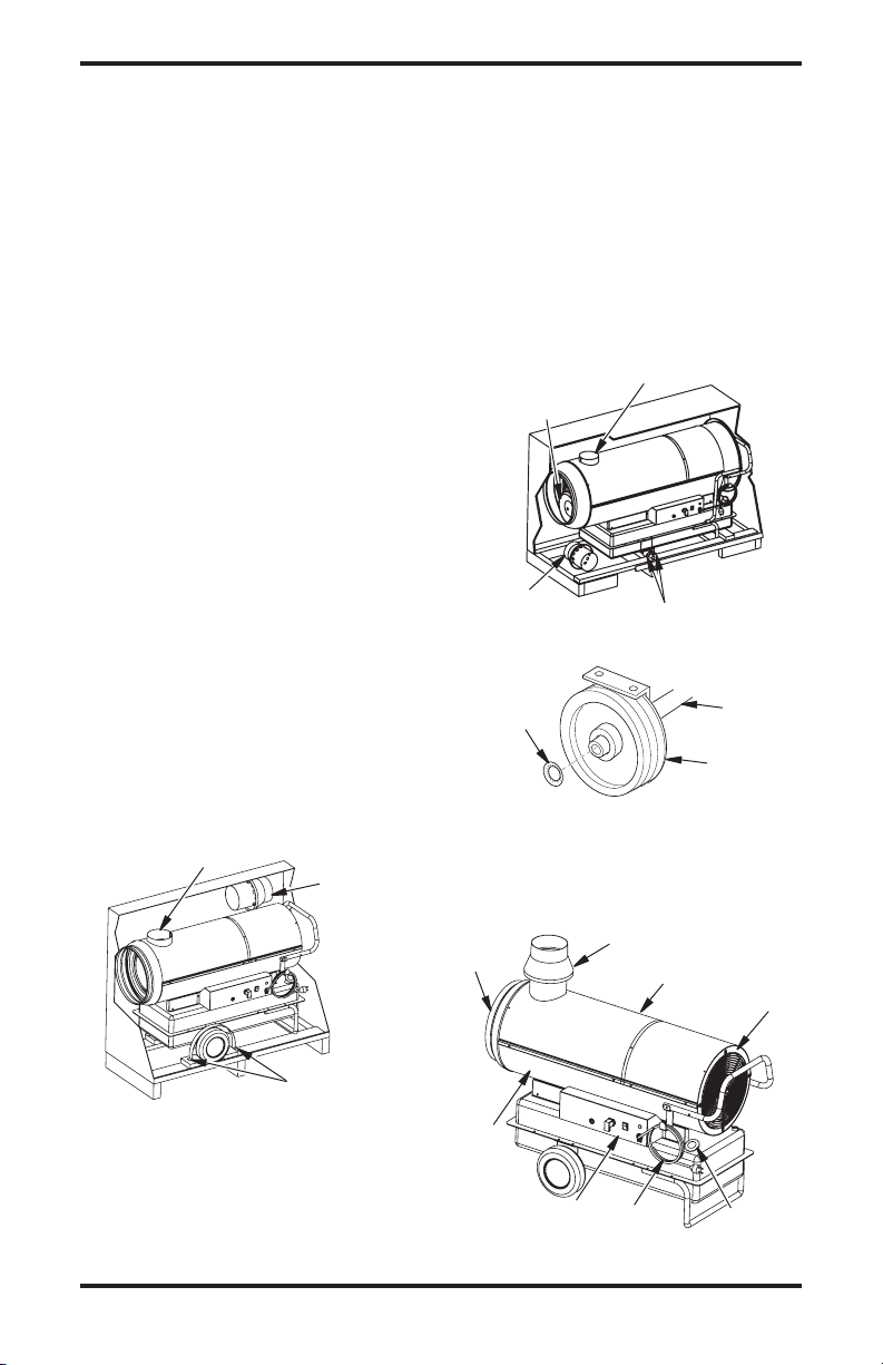
UNPACKING
MODEL 160-IF
1. Remove all the materials used to package the
heater for shipment.
2. Open the carton from the top.
3. Remove the flue connection from carton (see
Figure 1).
4. Lift up and remove cardboard packaging.
5. Unscrew the locking screws on wheel-lock
straps (see Figure 1).
6. Insert the flue connection onto the flue outlet
tube (see Figure 4).
7. Carefully lower the heater from pallet.
SAFETY INFORMATION
Continued
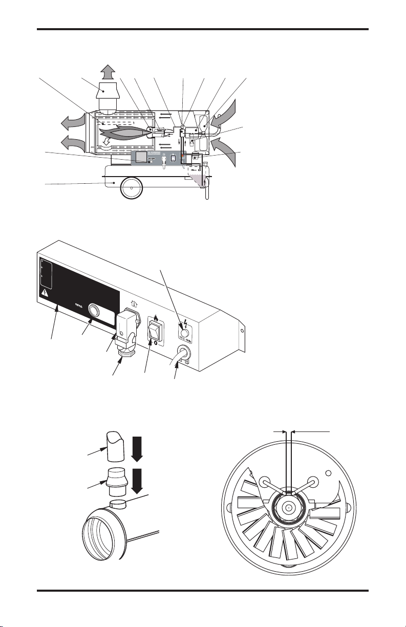
Hot Air
Output
Flue Connection
Upper
Shell
Fuel Tank
Cap
Power
Cable
Control
Panel
Lower
Shell
Fan
Guard
Figure 4 - Vented Portable Forced Air Heater
Figure 1 - Removing 160-IF from Carton
Figure 2 - Removing 280-IF from Carton
Flue
Connection
Locking Screws
Locking Screws
Flue
Connection
Wheels Stored
for Shipping
Flue Outlet Tube
Flue Outlet
Tube
Figure 3 - Wheel/Axle Assembly for
280-IF
Lock
Washer
Axle
Wheel
MODEL 280-IF
1. Remove all the materials used to package the
heater for shipment.
2. Open the carton from the top.
3. Lift up and remove cardboard packaging.
4. Unscrew the locking screws on hub locking
bar (see Figure 2).
5. Remove the wheels from the hot air outlet
(stored for shipping).
6.
Lift the heater from the air outlet end.
7. Insert the wheels onto the axle.
8. Insert the locking washer (which is in the
documentation envelope) with the convex side
towards the exterior of the machine; using a
hammer and an appropriate-sized spanner, tap
it gently to fix it into position (see Figure 3).
9. Carefully lower the heater from pallet.
PRODUCT
IDENTIFICATION
www.desatech.com
114909-01A
4
4.
Flip switch (3 on Electric Control Panel,
page 7) to the position with the symbol:
- the fan should start and after several
seconds the heater should ignite.
The first time the heater is used or after the fuel
circuit has been completely drained, the flow of
fuel oil to the nozzle may be insufficient and may
activate the flame control, which will turn off the
heater; if this happens, wait for about a minute and
then press the reset button (1
on Electric Control
Panel, page 7
) to start the heater again.
TO STOP HEATER
1.
Move switch (3 on Electric Control Panel, page
7) to the “0” position or adjust the control mech
-
anism, for example turning the thermostat to a
lower position. The flame will go out and the fan
will continue to function until the combustion
chamber has cooled down completely.
2. Wait until fan stops before unplugging heater.
Unplug heater when not in use.
THERMOSTAT
OPERATION
The heater can only work automatically when a
thermostat is connected to it by attaching the cable
to terminals 2 and 3 of plug (4
on Electric Control
Panel, page 7
).
MOVING AND
TRANSPORTING HEATER
WARNING: Before moving
the heater you must turn the
heater off (see To Stop Heater),
disconnect the plug from the
power supply and wait for the
heater to cool.
Before lifting or moving the heater, make sure that
the fuel tank cap is firmly in place.
The heater may be supplied in a portable version,
with wheels or a suspended version, mounted on a
support structure and fixed in place with wires or
chains. In the former case, to move the heater, sim
-
ply grasp the support handle and move the heater.
In the latter case, the heater must be lifted with a
fork-lift truck or a similar piece of equipment.
FUELS
WARNING: Use only kero-
sene, #1/#2 diesel/fuel oil, JET A
or JP-8 fuels to avoid risk of fire or
explosion. Never use gasoline, oil
drained from crankcases, naph-
tha, paint thinners, alcohol or
other highly flammable fuels.
Use only kerosene, #1/#2 diesel/fuel oil, JET A
or JP-8 fuels. Heavier fuels such as No. 2 fuel
oil or No. 2 diesel fuel may also be used but will
result in:
• noticeable odor
• additional fuel filter maintenance
• the need for nontoxic, anti-icer additives in very
cold weather
Do not use fuels heavier than No. 2 grade or
heavy oils such as oil drained from crankcases.
These heavy oils will not ignite properly and will
contaminate the heater.
IMPORTANT: Use a KEROSENE ONLY (blue)
or DIESEL ONLY (yellow) storage container. Be
sure storage container is clean. Foreign matter
such as rust, dirt or water will cause the ignition
control assembly to shut down heater. Foreign
matter may also require heaterʼs fuel system to
be frequently cleaned.
TO START HEATER
IMPORTANT: Review and under-
stand the warnings in the
Safety
Information section, page 2. They
are needed to safely operate
this heater. Follow all local or-
dinances and codes when using
this heater.
1. Fill tank with fuel (see Fuels).
2.
Plug heater power cord into approved, grounded,
120V/60Hz, 3 prong outlet or extension cord.
Extension Cord Size Requirements
6 to 10 feet (1.8 to 3 meters) long, use 18 AWG
(0.75 mm
2
) rated cord
11 to 100 feet (3.3 to 30.5 meters) long, use
16 AWG (1.0 mm
2
) rated cord
101 to 200 feet (30.8 to 61 meters) long, use
14 AWG (1.5 mm
2
) rated cord
3. If a thermostat is connected, adjust it to the
maximum temperature.
www.desatech.com
5114909-01A
POSSIBLE CAUSE
1. No electric current
2. Incorrect setting on the thermo
-
stat (if fitted)
3. Faulty thermostat
4. Motor winding burnt out or
broken
5. Bearings of motor have seized
up
6. Motor capacitor has burned
out
7.
Thermostat plug not connected
TROUBLESHOOTING
OBSERVED FAULT
The fan does not come on and
the flame does not light
SOLUTION
1
A) Check the characteristics
of the electrical system (120 V
- 60 Hz)
B) Check that the sw itch
works and is in the correct
position
C) Check that the fuse has not
blown
2. Check that the thermostat
setting is correct (e.g. the
temperature setting on the
thermostat must be higher than
the ambient temperature)
3.
Replace the thermostat
4. Replace the motor
5. Replace the bearings
6. Replace the capacitor
7. Connect thermostat plug
PREVENTATIVE
MAINTENANCE
To ensure that the heater continues to work
properly, it is necessary to periodically clean the
combustion chamber, the burner and the fan.
WARNING The following
steps must be carried out before
servicing the heater: turn the
heater off, following the instruc
-
tions in the previous section;
disconnect the plug from the
power supply and wait for the
heater to cool.
Every 50 hours of use it is necessary to:
• Dismantle the filter cartridge, remove it and
clean it with clean fuel oil.
• Remove the exterior cylindrical casing and
clean the inside and the blades of the fan.
• Check the condition of the cables and the high
voltage connections on the electrodes.
• Dismantle the burner, clean the parts, then clean
the electrodes and adjust them, if necessary, to
the distance indicated in Electrode Spacing on
page 7.

www.desatech.com
114909-01A
6
POSSIBLE CAUSE
1. Ignitor is not functioning
2.
Faulty flame control
3.
Non-functioning photoelectric
cell
4. Fuel is not reaching the burner
or a sufficient amount is not
arriving
5.
Solenoid valve is not working
1.
Insufficient air for combustion
2. Too much air for combustion
3. Fuel is dirty or contains water
4. Air has filtered into the fuel
circuit
5. Inadequate quantity of fuel in
burner
6. Too much fuel in burner
1. Faulty fan thermostat
SOLUTION
1. A) Check the connections
of the ignition cables to the
electrodes and transformer
B) Check the position of the
electrodes and the distance
between them, in accordance
with the diagram on page 7
C) Check that the electrodes
are clean
D) Replac e the ignit ion
transformer
2. Replace the flame control
3. Clean or replace the photo-
electric cell
4. A) Check that the connection
between the pump and the
motor is intact
B) Check that air has not fil-
tered into the fuel circuit, check
the tubes and the filter seal
C) Clean or, if necessary,
replace the nozzle
5. A) Check the electrical con
-
nection
B) Check the LI thermostat
C) Clean or, if necessary,
replace the solenoid valve
1. A) Remove anything block
-
ing or obstructing the aspira-
tion and/or airflow ducts
B) Check the position of the
air regulation ring
C) Clean the burner disc
2. Check the position of the air
regulation ring
3. A) Replace the fuel with
clean fuel
B) Clean the fuel filter
4. Check the condition of the
tubes and the seal of the fuel
filter
5. A) Check the pump pressure
B) Clean or replace the nozzle
6.
A) Check the pump pressure
B) Replace the nozzle
1. Replace the solenoid valve
1. Replace the FA thermostat
OBSERVED FAULT
The fan comes on but the
flame does not light or does
not remain lit
The fan comes on and the flame
lights, but produces smoke
The heater does not turn off
The fan does not switch off
TROUBLESHOOTING
Continued
www.desatech.com
7114909-01A
HEATER FUNCTIONING DIAGRAM
ELECTRIC CONTROL PANEL
ELECTRODE SPACING
FLUE CONNECTIONS DIAGRAM
DIAGRAMS
1. Combustion chamber
2. Anti-wind flue connection
3. Burner
4. Nozzle
5. Fuel circuit
6. Fuel pump
7. Electric fuel valve
8. Motor
9. Fan
10. Cable winding bracket
11. Fuel filter
12. Fuel tank
13. Control panel
1 2 3 6 8 9
12
13
11
4
5 7
10
0.08" - 0.12"
(2-3 mm)
!
C
A
UT
IO
N
:
H
o
t
w
h
i
le
i
n
o
pe
rati
o
n
.
D
o
n
o
t
to
u
c
h.
Ke
e
p
c
h
il
d
ren,
a
n
im
a
ls
,
c
lo
th
in
g
a
n
d
c
o
m
b
us
t
i
bl
e
s
aw
a
y.
!
P
R
E
CA
UC
I
Ó
N:
C
al
ie
n
te
cu
a
nd
o
e
s
t
á
en
o
p
e
r
ac
ió
n
.
No
t
ocar
.
M
a
n
te
n
g
a
a lo
s
n
iñ
o
s
,
a
ni
m
a
l
e
s
,
v
e
s
t
im
e
nt
a
y
c
om
b
u
s
ti
b
l
es
a
le
-
j
ad
o
s.
!
AT
T
E
N
T
IO
N
:
L’
ap
pa
re
i
l
de
c
hauffage
e
s
t
b
rû
la
n
t
p
en
d
a
n
t
l
e
fo
n
c
t
i
o
n
ne
m
e
nt.
N
e
le
to
u
c
he
z
p
a
s
.
T
e
n
e
z
l
es
e
n
fa
n
ts
, les
a
nim
a
u
x
e
t
l
es
vê
t
e
m
e
n
t
s
à
l’
é
c
ar
t
d
e
c
e
t
ap
p
a
re
il
.
O
P
E
R
A
T
IN
G
I
N
S
T
R
U
C
T
IO
N
S
ST
A
RT
1
.
Fill
t
a
nk
-
U
se
o
nl
y
ke
ro
se
n
e
,
#
1
&
#
2
d
ie
se
l
a
n
d
f
u
el
o
il
,
JE
T
A
o
r
JP
-
8
f
ue
l
s.
2
.
P
lu
g
p
ow
e
r
cord
i
n
to
12
0V
/6
0
Hz
outl
et
.
Po
w
e
r
in
d
icator
lig
h
t
sh
o
ul
d
be
on
.
3
.
If
e
q
u
ip
pe
d
, ad
j
us
t th
e
r
m
o
s
ta
t
k
no
b
to
t
he wa
rm
es
t
sett
i
ng
.
4
.
P
u
s
h
ON
/
OF
F
sw
itch
t
o
O
N
( )
.
F
a
n
m
o
to
r
sh
ou
ld
s
t
ar
t
i
mm
e
d
ia
t
e
ly
.
He
a
te
r
wi
l
l
i
gn
i
te
wi
th
i
n
1
0
s
econds
.
5
.
If
eq
ui
p
pe
d,
ad
j
u
s
t
th
e
rm
osta
t to desired
s
etti
n
g
.
ST
OP
Pu
s
h
O
N
/
O
F
F
sw
it
c
h
to
OF
F
(
O).
F
a
n
m
o
to
r
wi
l
l
cont
i
n
u
e
to
r
u
n.
Do
n
o
t
un
plug he
a
te
r
u
n
t
i
l
c
o
o
l
in
g
c
y
cl
e
i
s
c
o
mp
l
e
te.
S
e
e
m
o
d
e
l
d
e
c
a
l
o
r
o
w
n
er
’s
m
a
n
u
a
l
f
or
a
d
d
i
t
io
n
a
l
o
p
e
r
a
t
i
n
g
i
n
s
t
r
u
c
-
t
io
n
s
,
s
a
fe
t
y
r
e
q
u
i
r
e
m
e
n
t
s
,
a
n
d
s
p
e
c
i
fi
c
a
t
i
o
n
s
.
O
PE
R
A
T
I
N
G
I
N
S
T
R
U
C
T
I
O
N
S
ST
A
R
T
1
.
Fill
t
a
n
k
-
U
se
o
nl
y
ker
os
e
n
e
,
#
1
&
#
2
d
ie
s
el
a
n
d
f
u
e
l
o
i
l
,
JE
T
A
o
r
JP
-
8
f
u
e
l
s.
2
.
P
lu
g
p
o
we
r
co
r
d
in
t
o
1
2
0V
/
6
0
H
z
o
u
t
le
t.
P
ow
er
i
n
d
icator
ligh
t
should
be
on
.
3
.
If
e
q
u
ip
pe
d
, adju
s
t
t
he
r
m
os
ta
t kn
o
b
to
t
he
warmes
t
se
t
t
i
n
g
.
4
.
P
u
sh
ON
/OFF
sw
it
ch
t
o
ON
(
)
. Fa
n
mo
t
or
s
h
o
u
ld
st
a
r
t
i
mm
e
di
-
a
tely
. He
a
te
r
wi
l
l
i
gn
i
te
wi
th
i
n
1
0
se
co
n
ds
.
5
.
If
eq
ui
p
pe
d, ad
j
us
t
ther
m
o
st
at
to desir
e
d sett
i
ng
.
ST
OP
Pu
s
h
O
N
/
O
F
F
s
w
i
t
c
h
to OF
F
(
O
)
.
F
an
mo
t
or
wi
l
l
co
n
ti
n
u
e
to
r
u
n.
Do
n
o
t
u
n
plug
h
e
a
te
r
u
nt
i
l co
o
l
in
g
c
y
cl
e
i
s
c
om
p
l
e
te
.
Se
e
mo
d
el
d
e
c
a
l
or
o
w
n
er
’
s
m
a
n
u
a
l
f
or
a
d
d
it
i
o
n
a
l
o
p
er
at
i
n
g
in
st
r
u
c
-
t
io
n
s
,
s
a
fe
t
y
r
e
q
u
i
r
e
m
e
n
t
s
,
an
d
s
p
e
c
i
fi
c
a
t
i
o
n
s
.
O
PE
R
A
T
I
N
G
IN
S
TR
U
C
T
IO
NS
ST
A
RT
1.
Fi
l
l
t
a
n
k
-
Us
e
o
nl
y
ke
r
ose
ne
,
#
1
&
#
2
d
iese
l
a
n
d
f
u
el
o
il
,
JET
A
o
r
JP-8
f
u
e
ls
.
2.
P
lu
g
p
ow
e
r
co
rd
in
t
o
1
2
0
V
/
6
0
Hz
o
u
t
le
t
.
Po
w
e
r
i
n
d
i
ca
to
r
li
gh
t
s
h
ou
l
d
be
o
n.
3.
If
eq
ui
p
pe
d
,
a
d
ju
s
t
the
rm
os
t
at
k
n
ob
to the
wa
r
m
es
t
sett
i
ng
.
4
.
P
us
h
ON
/
OF
F
sw
it
ch
t
o
ON ( )
.
F
an
mo
t
or
should
st
a
r
t
i
mm
e
d
i
-
ate
l
y
. He
at
e
r
wi
l
l
i
g
n
i
te
wi
t
hi
n
1
0
s
econ
d
s
.
5
.
I
f
e
q
u
i
p
pe
d,
ad
j
us
t
t
he
r
m
os
tat
t
o
d
esired
s
e
tt
i
n
g
.
S
T
OP
Pu
s
h
ON/O
F
F
swit
c
h
to
OFF
(
O
).
F
a
n
moto
r
wi
l
l
c
o
n
t
in
u
e
t
o
r
u
n.
Do
no
t
u
np
l
u
g
he
at
e
r
un
ti
l
c
o
ol
i
n
g
cy
c
le
is
c
o
mp
l
e
t
e
.
S
e
e
m
o
d
e
l
d
e
c
a
l
or
o
w
ne
r
’
s
m
a
n
u
a
l
f
or
a
d
d
it
io
n
a
l
o
pe
r
a
t
i
ng
i
n
s
t
r
u
c
-
t
i
o
n
s
,
s
a
fe
ty
r
e
qu
i
r
e
m
e
n
t
s,
a
n
d
s
pe
c
i
fic
a
t
i
o
n
s
.
2
7
0
0
1
I
n
d
us
t
ri
a
l
D
ri
v
e
P.
O
.
B
o
x
9
00
4
Bo
wl
i
n
g
G
r
e
en
,
K
y
4
2
1
0
2
w
ww
.
d
e
s
at
e
c
h
.
co
m
1
13
3
44
-0
8
U
N
PL
U
G
HE
A
T
E
R
B
E
F
O
R
E
R
E
M
O
V
I
NG
CO
VE
R
U
N
P
LU
G
HE
A
T
E
R
B
E
F
O
RE
R
E
M
O
V
I
N
G
CO
V
ER
U
N
P
L
U
G
HE
A
T
E
R
B
E
F
O
R
E
RE
M
OV
I
N
G
C
OV
E
R
Ma
de
i
n
I
t
a
l
y
FLA
M
E
C
O
N
TRO
L
R
E
S
E
T
F
LA
M
E
CO
N
TR
O
L
R
E
S
E
T
FLA
M
E
C
O
N
T
RO
L
R
E
S
E
T
M
a
n
uf
ac
t
u
re
d
f
o
r
:
1. Reset button
2. Operation label
3. Main switch
4. Socket for ambient ther
-
mostat
5. Power cable
6. Power indicator
7. Thermostat plug (must be
secure if no control device
is used)
2
1
3
4
7
5
6
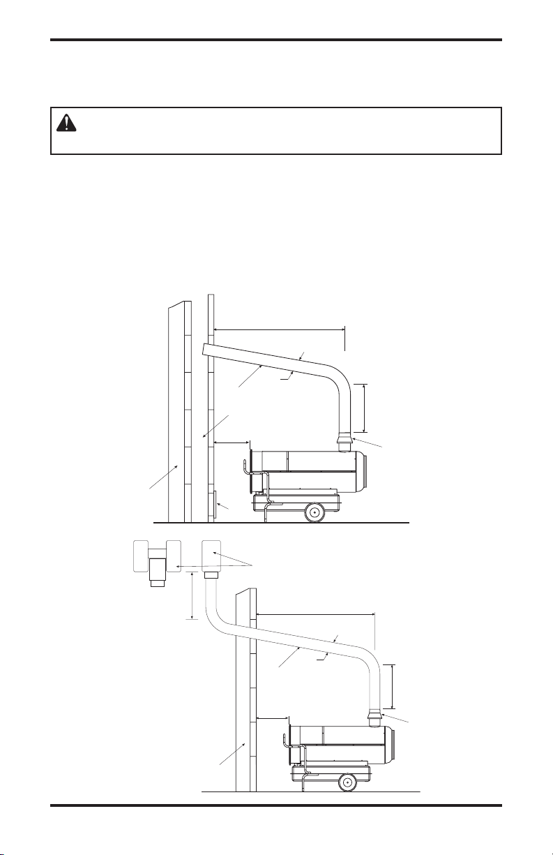
Pipe -
6" Diameter
Flue
Connector
www.desatech.com
114909-01A
8
EXHAUST PIPE POSITIONING DIAGRAM
DIAGRAMS
Continued
5
4
A
3
2
D
C
1
B
A
6
2
D
C
1
B
5
E
WARNING: The diagrams are typical; the installation of the flue
must meet current legal norms.
1. Anti-wind device fitted with the heater
2. Horizontal crosspiece with a minimum
upwards angle of at least 5°, minimum 1"
up for every 12" of horizontal travel
3. Flue with minimum internal dimensions
of 8" x 8"
4. Anti-explosion/flue inspection shutter
5. External buffer wall
6. H-shape draw activator
A. Minimum 3 ft.
B. Minimum 3 ft.
C. As short as possible
D. Equal to or greater than the diameter of
the burner’s flue output
E. Minimum 3 ft.
www.desatech.com
9114909-01A
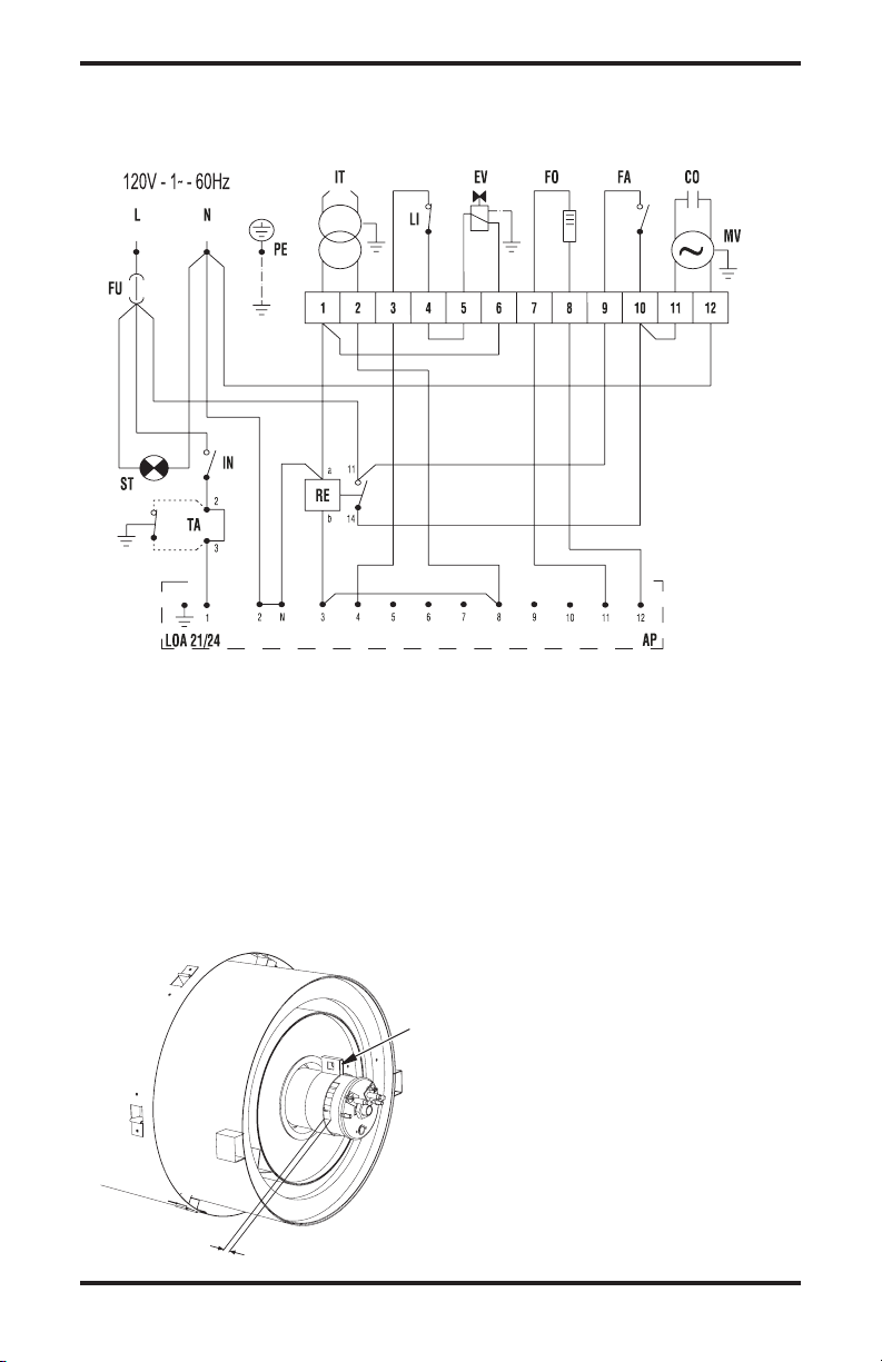
ELECTRIC WIRING DIAGRAM
DIAGRAMS
Continued
REGULATION OF COMBUSTION AIR SHUTTER ADJUSTMENT
A
160-IF A=19/32" (15mm)
280-IF A=5/16" (8mm)
FU Fuse
6A 160-IF
10A 280-IF
IT High voltage transformer
LI Safety thermostat
EV Solenoid valve
FO Photocell
FA Fan thermostat
CO Capacitor
MV Fan motor
ST Power light
IN Switch
TA Ambient thermostat socket
RE Relay
AP Control box
Air Shutter
www.desatech.com
114909-01A
10
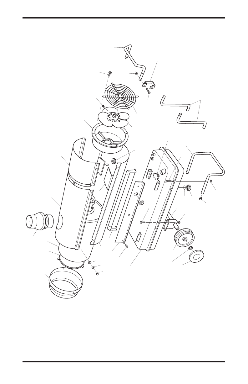
ILLUSTRATED PARTS BREAKDOWN
MODELS: 160-IF, 280-IF
1
2
33
3
4
8
11
12
13
14
15
16
17
18
19
20
21
22
23
24
25
35
30
34
26
27
28
29
30
31
36
7
6
28
10
9
28
5
32
www.desatech.com
11
114909-01A
KEY PART NUMBER
NO. 160-IF 280-IF DESCRIPTION QTY.
1 115130-01 115130-02 Rear Handle 1
2 115131-01 115131-02 Frame Support 1
3 115132-01 115132-02 Outlet Cone 1
4 115133-01 115133-01 Cap Plug 2
5 115134-01 115134-02 Axel 1
6 115135-01 115135-02 Wheel 2
7 115136-01 115136-02 Wheel Lock Washer 2
8 115137-01 115138-01 Fuel Tank 1
9 115139-01 115139-01 Drain Plug 1
10 115140-01 115140-01 Drain Plug O-Ring 1
11 115141-01 115141-01 Fuel Cap 1
12 115142-01 115142-02 Fan Guard 1
13 115143-01 115144-01 Fan 1
14 115145-01 115145-01 Fan Set Screw 1
15 115146-01 115147-01 Motor Support 1
16 115148-01 115148-02 Air Deflector 3
17 115149-01 115150-01 Combustion Chamber 1
18 115151-01 115152-01 Flame Guard Shield 1
19 115153-01 115154-01 Shell Support, Right 1
20 115155-01 115156-01 Shell Support, Left 1
21 115157-01 115158-01 Lower Shell 1
22 115159-01 115160-01 Upper Shell 1
23 115161-01 115162-01 Upper Shell, Rear Cover 1
24 115163-01 115163-01 Flue Connector 1
25 115164-01 115164-01 Cable Bushing 1
26 115165-01 115165-01 Screw, M5 x 16 4
27 115166-01 115166-01 Screw, 10 x 1/2" 6
28 115248-01 115248-01 Nut, M6 10
29 115249-01 115249-01 Sleeve Screw 6
30 115250-01 115250-01 Screw, M6 x 16 4
31 115251-01 115251-01 Screw, 14 x 1/2" 4
32 115167-01 115167-01 Clip Nut 6
33 115168-01 115168-01 Screw, M6 x 30 4
34 115169-01 115169-01 Power Cord Hook 2
35 ----- 115170-01 Handle Support Bar 2
36 115171-01 115171-02 Yellow Wheel Plug 2
PARTS LIST
This list contains replaceable parts used in your heater. When ordering parts, be sure to provide the correct
model and serial numbers (from the model plate), then the part number and description of the desired part.
www.desatech.com
114909-01A
12
1
2
3
4
5
6
7
8
9
10
11
12
13
14-1
14-2
14-3
14-4
15
16
17
18
19
20
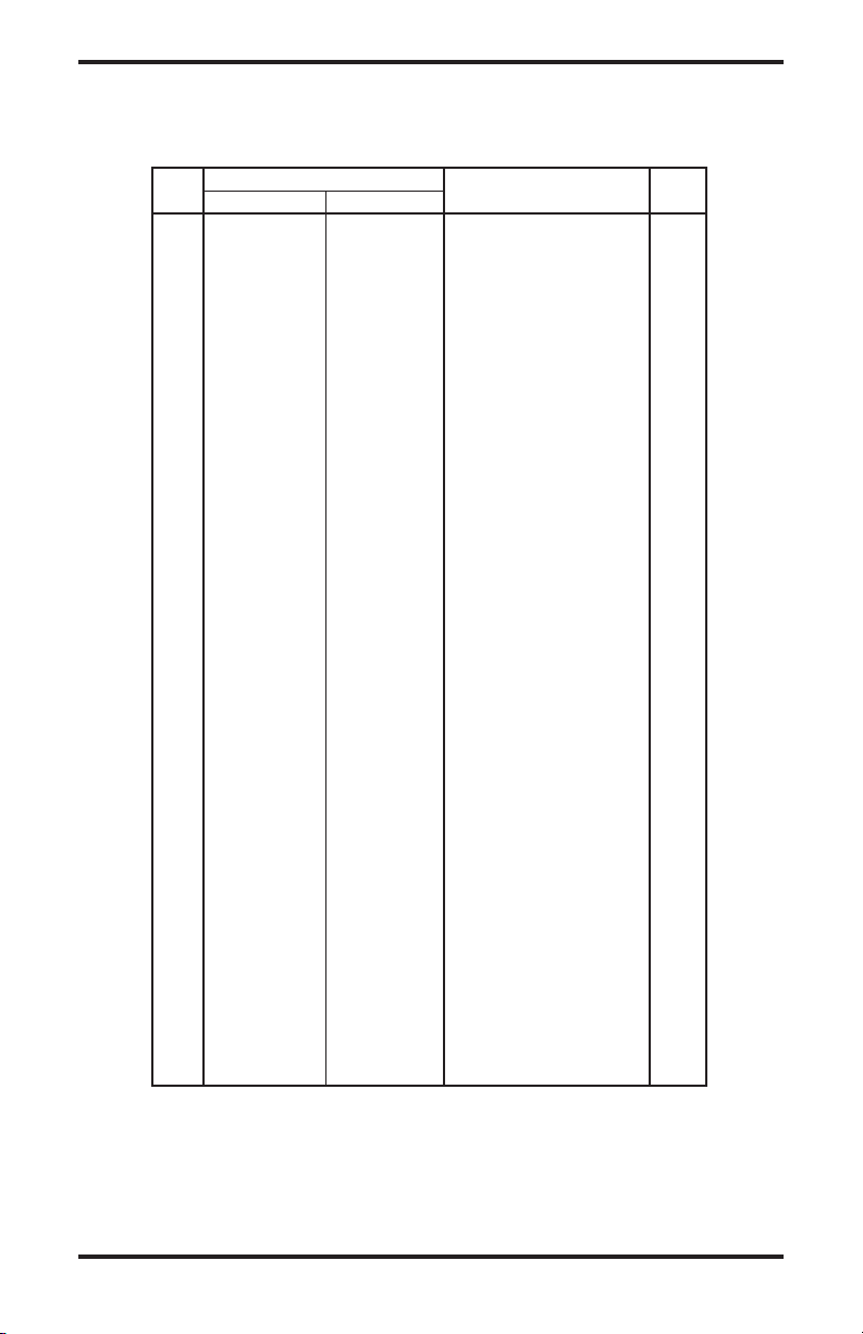
ILLUSTRATED PARTS BREAKDOWN AND PARTS LIST
CONTROL BOX FOR 160-IF, 280-IF
KEY PART NUMBER
NO. 160-IF 280-IF DESCRIPTION QTY.
1 115172-01 115172-01 Control Box Support 1
2 Control Box Base 1
3 115173-01 115173-01 Control Box 1
4 115174-01 115174-01 Transformer 120V 1
5 115175-01 115175-02 High Tension Cable 2
6 115176-01 115176-01 Relay 1
7 115177-01 115177-01 Terminal Board 1
8 115178-01 115178-01 Electrical Component Cover 1
9 115179-01 115179-01 Power Light 1
10 115180-01 115180-01 Switch Cover 1
11 115181-01 115181-01 Switch 1
12 115182-01 115182-01 4-Pin Socket 1
13 115183-01 115183-01 Plug 1
14 115184-01 115184-01 Electric Wire with Plug and
Cable Fastener 1
14-1 115185-01 115185-01 Cable Fastener 1
14-2 115186-01 115186-02 Fuse 1
14-3 115187-01 115187-01 Electric Wire with Plug 1
14-4 115188-01 115188-01 Screw 8 x 3/8" 2
15 115189-01 115189-01 Screw 8 x 1
1
/
2
" 2
16 115190-01 115190-01 Screw 4 x 1/2" 2
17 115191-01 115191-01 Clamp Nut M6 2
18 115250-01 115250-01 Screw M6 x 16mm 2
19 115192-01 115192-01 Screw 4 x 3/8" 2
www.desatech.com
13114909-01A
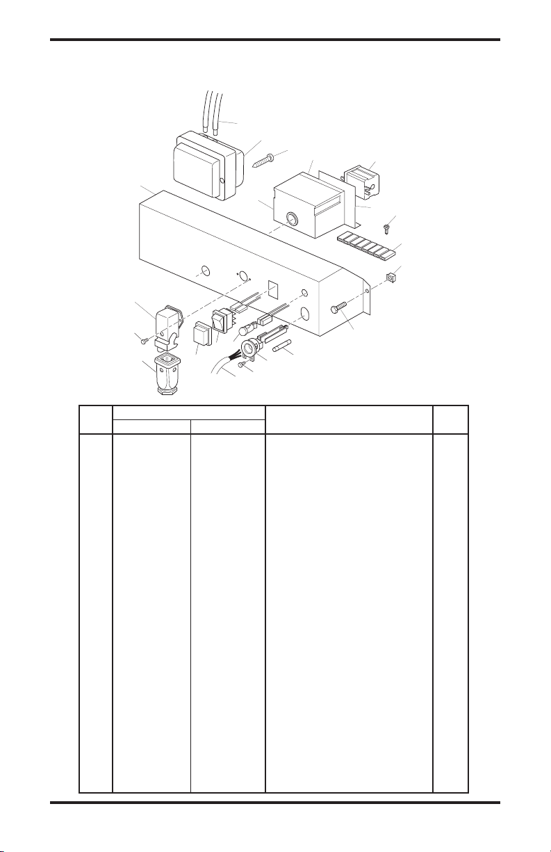
ILLUSTRATED PARTS BREAKDOWN AND PARTS LIST
FUEL FILTER ASSEMBLY FOR 160-IF, 280-IF
1
1
2
3
4
5
6
7
8
11
11
9
10-1
10-2
10-3
10-4
10-5
KEY PART NUMBER
NO. 160-IF 280-IF DESCRIPTION QTY.
1 115252-01 115252-01 Flex Fuel Tube 1
2 115253-01 115253-01 Cable Bushing 1
3 115193-01 115193-02 Fuel Pickup Tube 1
4 115194-01 115194-01 Straight Connection 1/4" 1
5 115195-01 115195-01 Nut 3/8" x 5 1
6 115196-01 115196-01 Filter Support Bracket 1
7 115197-01 115197-01 Double Male Connector 1
8 115198-01 115198-01 90˚ Elbow 1
9 115199-01 115199-01 Straight Connector 1
10 115200-01 115200-01 Filter Assembly 1
10-1 115201-01 115201-01 Filter O-Ring 1
10-2 115202-01 115202-01 Top Fuel Filter Seal 1
10-3 115203-01 115203-01 Filter Element 1
10-4 115204-01 115204-01 Filter Housing 1
10-5 115205-01 115205-01 Lower Oil Filter Seal 1
11 115206-01 115206-01 Straight Connector 1/8" 2
www.desatech.com
114909-01A
14
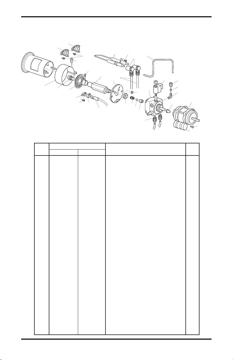
ILLUSTRATED PARTS BREAKDOWN AND PARTS LIST
MOTOR, FUEL PUMP AND BURNER COMPONENTS FOR 160-IF, 280-IF
KEY PART NUMBER
NO. 160-IF 280-IF DESCRIPTION QTY.
1 115207-01 115207-02 Electrode Wire 2
2 115208-01 115208-01 Cool Off Thermostat (Fan) 1
3 115209-01 115209-01 Overheat Thermostat (Blue Dot) 1
4 115210-01 115210-01 Ceramic Electrode 2
5 115211-01 115211-01 Cable Connector (90˚) 2
6 115212-01 115212-01 Fuel Line 1
7 115213-01 115213-01 High Pressure Pump 1
7-1 115214-01 115214-01 Solenoid Valve 1
7-2 115215-01 115215-01 Pump Body/Housing 1
8 115216-01 115216-01 Connector 1/4" 2
9 115217-01 115217-02 Coupling, Motor/Pump 1
10 115218-01 115218-01 Connector 90˚ 1/8" 1
11 115219-01 115219-01 Ferrule 4mm 2
12 115220-01 115220-01 Ferrule Nut 2
13 115221-01 115222-01 Motor 1
14 115223-01 115223-01 Fuel Line Fitting 1
15 115224-01 115224-01 Connector 1/8" 1
16 115225-01 115225-01 Nut, M14 1
17 115226-01 115226-01 Burner Flange 1
18 115227-01 115227-01 Nozzle Support 1
19 115228-01 115228-01 Diffuser 1
20 115229-01 115229-02 Nozzle, 80˚ 1
21 115230-01 115230-01 Air Regulation Strap 1
22 115231-01 115231-01 Photocell 1
23 115232-01 115232-01 Photocell Clamp 1
24 115233-01 115233-01 Photocell Flange 1
25 115234-01 115234-01 Screw 8 x 3/8" 3
26 115235-01 115235-01 Nut, M5 1
27 115236-01 115236-01 Screw, Allen 1
28 115237-01 115237-01 Screw 6 x 1/2" 1
29 115238-01 115238-01 Screw M4 x 8mm, Allen 1
30 115239-01 115239-01 Screw M6 x 25mm, Allen 1
2
1
3
4
5
6
7-1
7-2
14
9
8
12
11
1516
26
17
18
29
25
25
30
19
20
10
11
12
27
13
21
24
28
23
22
Blue Mark
www.desatech.com
15114909-01A
SPECIFICATIONS
Model Size 160-IF 280-IF
Maximum Output Rating (Btu/Hr) 158,000 278,000
Net Output Rating (Btu/Hr) 133,000 234,400
Fuel Use only kerosene, #1/#2 diesel/fuel oil, JET A or JP-8 fuels*
Fuel Tank Capacity (U.S. Gal./Liters) 17/65 28/105
Fuel Consumption
(Gal. Per Hr/Liters Per Hr) 1.27/4.81 2.22/8.40
Pump Pressure (psi) 145 174
Electric Requirements 120 V/60 HZ (Same Both Models)
Amperage (Normal Run) 4.8 8.5
Motor RPM 2850 3490
Hot Air Output (CFM) 1,060 1,940
Shipping Weight 190/86 320/145
(Approximate lbs./kg)
Heater Weight without Fuel 161/74 273/124
(Approximate lbs./kg)
* Use of #2 diesel & fuel oil will result in noticeable odor and could require additional fuel filter main
-
tenance. Use in extreme cold temperatures may require nontoxic anti-icer additives.
TECHNICAL SERVICE
You my have further questions about installation,
operation or troubleshooting. If so, contact DESA
Heating Productsʼ Technical Service Department
at 1-866-672-6040. When calling please have your
model and serial numbers of your heater ready. You
can also visit DESA Heating Productsʼ technical
services web site at www.desatech.com.
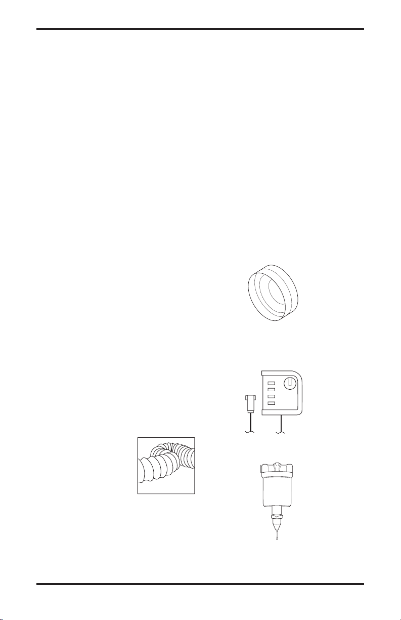
ACCESSORIES
Purchase accessories and parts from your nearest
dealer or service center. If they can not supply
these accessories or parts, either contact your
nearest parts dealer or DESA Heating Products
at 1-866-672-6040 for referral information. Parts
Centrals are listed in the Authorized Service Center
booklet supplied with heater.
FLEXIBLE VENT
HOSE
HA3220 for Model 160-IF
Model 160-IF can only con
-
nect one 20' section of vent
hose. Must be used wih hose
connector kit HA3230.
HA3221 for Model 280-IF
Model 280-IF can connect up to two 20' sections
of vent hose. Must be used wih hose connector
kit HA3231.
HOSE CONNECTOR KIT
HA3230 for Model 160-IF
HA3231 for Model 280-IF
EXTERNAL THERMOSTAT - HA3210
EXTREME COLD FUEL OIL PRE-HEATER
HA3211
Loading...