


 Loading...
For U.S.A.,Canada & Europe model
SERVICE MANUAL |
Ver. 1 |
|
MODEL SYS-76HT
SPEAKER SYSTEM PACK
●For purposes of improvement, specifications and design are subject to change without notice.
●Please use this service manual with referring to the operating instructions without fail.
●Some illustrations using in this service manual are slightly different from the actual set.
|
●8
●,
TOKYO JAPAN
Denon Brand Company, D&M Holdings Inc.
X0251 V.01 DE/CDM 0507
SYS-76HT
SAFETY PRECAUTIONS
The following check should be performed for the continued protection of the customer and service technician.
LEAKAGE CURRENT CHECK
Before returning the unit to the customer, make sure you make either (1) a leakage current check or (2) a line to chassis resistance check. If the leakage current exceeds 0.5 milliamps, or if the resistance from chassis to either side of the power cord is less than 460 kohms, the unit is defective.
|
|
|
|
|
|
|
|
|
500 |
|
|
|
|
|
1 Ω |
|
|

(1)
(2)

さい。特に配線図、部品表に
|
|
|
|
|
|
|
|
|
|
|
|
|
|
|
|
|
|
|
|
|
|
|
|
|
|
|
(1) … |
|
|
|
(2) … |
|
|
||
|
|
|
|
|
|
|
|
|
|
|
|
2
3
|
|
|
|
|
NORMAL |
|
|
|
|
|
|
|
|
|
U203 |
|
|
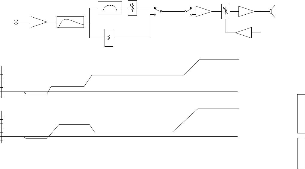
LINE INPUT |
|
CROSSOVER |
VOL |
SW202 |
REVERSE |
PHASE |
POWER AMP |
|
|
U201 |
CONTROL |
SPEAKER |
|||||
|
|
|||||||
|
|
DIRECT |
|
|
|
|||
|
|
|
|
|
|
|
|
|
|
|
HPF |
|
MODE SW |
|
|
|
|
|
|
|
|
|
|
U203 |
|
|
|
|
|
|
|
|
|
|
|
|
|
|
|
|
|
|
ALC |
|
|
|
DIRECT MODE |
|
|
|
|
|
|
|
|
ATT |
|
|
|
+50.5dB 20V/4ohrm THD 0.7% (ALCON) |
||
|
|
|
|
|
|
|||
(dB) |
|
|
|
|
|
|
at 55Hz |
|
40 |
|
+20dB |
|
|
|
|
|
|
|
|
|
|
|
|
|
|
|
20 |
|
+4.34dB |
|
|
|
|
|
|
75mV |
|
|
|
|
|
|
|
|
0 |
|
|
|
|
|
|
|
|
-10 |
-1dB |
|
|
|
|
|
|
|
(dB) |
|
|
|
|
|
+27.2dB 20V/4ohrm THD 0.7% (ALCON) |
||
|
|
|
|
|
|
|
|
|
|
|
|
|
|
|
|
at 55Hz |
|
40 |
|
+4.34dB |
|
|
|
|
|
|
|
|
|
|
|
|
|
|
|
20 |
|
|
+1.84dB |
|
|
|
|
|
|
|
|
|
|
|
|
|
|
830mV |
|
|
|
|
|
|
|
|
0 |
|
|
|
|
|
|
|
|
-10 |
-1dB |
|
|
|
|
|
|
|
DIAGRAM LEVEL / BLOCK 76-DSW
76HT-SYS Section 76-DSW
DSW-76 Section |
|
SYS-76HT |
|
|
|
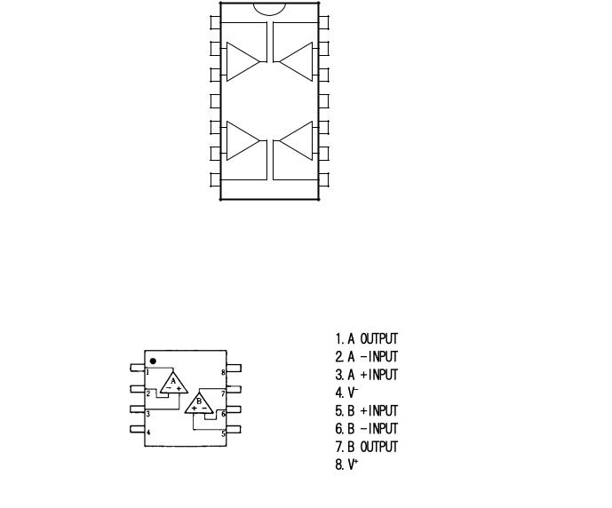
DSW-76 SEMICONDUCTORS
Only major IC's are shown,generai IC's etc. are omitted to list.
|
|
||||
IC's |
|
|
|
|
|
TL074CN (U201-203) PRE-AMP P.W.B. UNIT |
|
|
|
||
Output 1 1 |
|
|
14 |
Output 4 |
|
Inverting Input 1 |
2 |
- |
- |
13 |
Inverting Input 4 |
Non-inverting Input 1 |
3 |
+ |
+ |
12 |
Non-inverting Input 4 |
|
|
||||
VCC + |
4 |
|
|
11 |
VCC - |
Non-inverting Input 2 |
5 |
+ |
+ |
10 |
Non-inverting Input 3 |
Inverting Input 2 |
6 |
- |
- |
9 |
Inverting Input 3 |
|
|
||||
Output 2 |
7 |
|
|
8 |
Output 3 |
NJM4558D (U101) AMP P.W.B. UNIT
4

DSW-76 Section |
|
SYS-76HT |
|
|
|
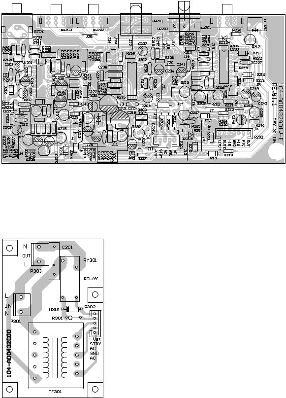
DSW-76 PRINTED WIRING BOARDS (1/2)
AMP P.W.B. UNIT
5
DSW-76 Section |
|
SYS-76HT |
|
|
|
DSW-76 PRINTED WIRING BOARDS (2/2)
PRE-AMP P.W.B. UNIT
POWER P.W.B. UNIT
6
NOTE FOR PARTS LIST
•Part indicated with the mark "nsp" are not always in stock and possibly to take a long period of time for supplying, or in some case supplying of part may be refused.
•When ordering of part, clearly indicate "1" and "I" (i) to avoid missupplying.
•Ordering part without stating its part number can not be supplied.
•Part indicated with the mark " " is not illustrated in the exploded view.
•Not including Carbon Film Resister ±5%, 1/4W Type in the P.W.Board parts list. (Refer to the Schematic Diagram for those parts.)
•Not including Carbon Chip Resister 1/16W Type in the P.W.Board parts list. (Refer to the Schematic Diagram for those parts.)
WARNING:
Parts marked with this symbol ! have critical characteristics. Use ONLY replacement parts recommended by the manufacturer.
l Resistors
Ex.: RN |
14K |
2E |
182 |
G |
FR |
|||
Type |
Shape |
Power ResistAllowable |
Others |
|||||
|
|
and per- |
|
ance |
error |
|
|
|
|
|
|
|
|
||||
|
|
formance |
|
|
|
|
|
|
|
|
|
|
|
|
|
||
|
|
|
|
|
|
|
|
|
DSW-76 Section |
|
SYS-76HT |
|
|
|
nsp
" " " "
3.
!
± 5% 1/4W
1/16W
さい。
|
RN |
|
14K |
|
2E |
182 |
|
|
G |
|
FR |
|||||||
|
|
|
|
|
|
|
|
|
|
|
|
|
|
|
|
|
|
|
|
|
|
|
|
|
|
|
|
|
|
|
|
|
|
|
|
|
|
|
|
|
|
|
|
|
|
|
|
|
|
|
|
|
|
|
|
|
RD |
: Carbon |
2B |
: 1/8W |
F |
: ±1% |
P |
: Pulse-resistant type |
RC |
: Composition |
2E |
: 1/4W |
G |
: ±2% |
NL : Low noise type |
|
RS |
: Metal oxide film |
2H |
: 1/2W |
J |
: ±5% |
NB : Non-burning type |
|
RW : Winding |
3A |
: 1W |
K |
: ±10% |
FR : Fuse-resistor |
||
RN |
: Metal film |
3D |
: 2W |
M |
: ±20% |
F |
: Lead wire forming |
RK |
: Metal mixture |
3F |
: 3W |
|
|
|
|
|
|
3H |
: 5W |
|
|
|
|
|
|
|
|
|
|
|
|
] Resistance |
|
|
|
|
||||
1 |
8 |
2 |
|
|
|
1800 ohm = 1.8 kohm |
||
|
s |
s |
|
|
|
Indicates number of zeros after effective number. |
||
|
|
|
|
|
|
|
|
|
|
|
|
|
|
|
|
|
2-digit effective number. |
• Units: ohm |
|
|
||||||
|
|
|
|
|||||
1 |
|
R |
2 |
|
|
|
1.2 ohm |
|
|
s |
s |
|
|
|
1-digit effective number. |
||
|
|
|
|
|
|
|
|
|
|
|
|
|
|
|
|
|
2-digit effective number, decimal point indicated by R. |
• Units: ohm |
|
|
|
|||||
|
|
|
|
|||||
RD |
: |
|
|
2B |
: 1/8 |
W |
|
F : |
±1% |
|
P |
: |
|||
RC |
: |
|
|
2E |
: 1/4 |
W |
|
G : |
±2% |
|
NL : |
||||
RS |
: |
|
|
2H |
: 1/2 |
W |
|
J : |
±5% |
|
NB : |
||||
RW : |
|
3A |
: 1 |
W |
|
K : |
±10% |
|
FR |
: |
|||||
RN |
: |
|
|
3D |
: 2 |
W |
|
M : |
±20% |
|
F |
: |
|||
RK |
: |
|
|
3F |
: 3 |
W |
|
|
|
|
|
|
|||
|
|
|
|
3H |
: 5 |
W |
|
|
|
|
|
|
|||
|
|
|
|
|
|
|
|
|
|
|
|
|
|
|
|
|
18 |
|
2 |
|
Ö |
|
1800 |
=1.8k |
|
|
|
||||
|
|
|
|
|
|
|
2 |
|
|
|
0 |
|
|
|
|
|
|
|
|
|
|
|
|
|
|
|
|
|
|||
|
|
|
|
|
|
|
|
|
|
|
|
|
|||
|
|
|
|
|
|
|
|
|
|
|
|
|
|
||
|
1R |
|
2 |
|
|
1.2 |
|
|
|
|
|||||
|
|
|
Ö |
|
|
|
|
|
|||||||
|
|
|
|
|
|
|
|
1 |
|
|
|
|
|
|
|
|
|
|
|
|
|
|
|
|
|
|
|
|
|
|
|
|
|
|
|
|
|
|
|
|
|
|
|
|
|
|
|
|
|
|
|
|
|
|
|
2 |
|
|
|
|
R |
|
|
|
|
|
|
|
|
|
|
|
|
|
|
|
|||
l Capacitors
Ex.: |
CE |
|
04W |
|
1H |
2R2 |
M |
|
BP |
||||||||||||||
|
Type |
|
Shape |
Dielectric Capacity Allowable Others |
|||||||||||||||||||
|
|
|
|
|
|
|
and perstrength |
|
|
|
error |
|
|
||||||||||
|
|
|
|
|
|
|
formance |
|
|
|
|
|
|
|
|
|
|
|
|
|
|
||
|
|
|
|
|
|
|
|
|
|
|
|
|
|
|
|
|
|
|
|
|
|
|
|
|
|
|
|
|
|
|
|
|
|
||||||||||||||
CE |
: Aluminum foil |
|
0J |
: 6.3V |
F |
: ±1% |
|
|
HS : High stability type |
||||||||||||||
|
electrolytic |
|
|
|
|
|
|
|
|
|
|
: ±2% |
|
|
|
|
|
||||||
CA |
: Aluminum solid |
|
1A |
: 10V |
G |
|
|
BP : Non-polar type |
|||||||||||||||
|
electrolytic |
|
|
|
|
|
|
|
|
|
|
: ±5% |
|
|
|
|
|
||||||
CS |
: Tantalum electrolytic |
1C |
: 16V |
J |
|
|
HR : Ripple-resistant type |
||||||||||||||||
CQ : Film |
|
|
|
|
|
|
|
1E |
: 25V |
K |
: ±10% |
|
|
DL : For change and discharge |
|||||||||
CK |
: Ceramic |
|
|
|
|
1V |
: 35V |
M |
: ±20% |
|
|
HF : For assuring high |
|||||||||||
|
|
|
|
|
|
|
|
|
|
|
|
|
|
|
|
|
|
|
|
|
|
requency |
|
CC : Ceramic |
|
|
|
|
1H |
: 50V |
Z |
: +80% |
|
|
U |
: UL part |
|||||||||||
CP |
: Oil |
|
|
|
|
|
|
|
2A |
: 100V |
|
–20% |
|
|
C |
: CSA part |
|||||||
CM : Mica |
|
|
|
|
|
|
|
2B |
: 125V |
P |
: +100% |
|
W |
: UL-CSA type |
|||||||||
CF |
: Metallized |
|
|
|
2C |
: 160V |
|
–0% |
|
|
F |
: Lead wire forming |
|||||||||||
CH : Metallized |
|
|
|
2D |
: 200V |
C |
: ±0.25pF |
|
|
|
|||||||||||||
|
|
|
|
|
|
|
|
|
|
2E |
: 250V |
D |
: ±0.5pF |
|
|
|
|
|
|||||
|
|
|
|
|
|
|
|
|
|
2H |
: 500V |
= |
: Others |
|
|
|
|
|
|||||
|
|
|
|
|
|
|
|
|
|
2J |
: 630V |
|
|
|
|
|
|
|
|
||||
|
|
|
|
|
|
|
|
|
|
||||||||||||||
] Capacity (electrolyte only) |
|
|
|
|
|
|
|
|
|||||||||||||||
2 |
2 |
|
2 |
|
|
|
2200µF |
|
|
|
|
|
|
|
|
||||||||
s |
s |
|
|
|
Indicates number of zeros after effective number. |
||||||||||||||||||
|
|
|
|
|
|
|
|
|
|||||||||||||||
|
|
|
|
|
|
|
|
|
2-digit effective number. |
|
|
|
|
|
|||||||||
• Units: µF. |
|
|
|
|
|
|
|
|
|||||||||||||||
|
|
|
|
|
|
|
|
|
|
|
|
|
|
|
|
|
|
||||||
2 |
R |
2 |
|
|
|
2.2µF |
|
|
|
|
|
|
|
|
|
|
|||||||
s |
s |
|
|
|
1-digit effective number. |
|
|
|
|
|
|||||||||||||
|
|
|
|
|
|
|
|
|
|
|
|
|
|
||||||||||
|
|
|
|
|
|
|
|
|
2-digit effective number, decimal point indicated by R. |
||||||||||||||
• Units: µF. |
|
|
|
||||||||||||||||||||
|
|
|
|
|
|
|
|
|
|
|
|
|
|
|
|
|
|
||||||
] Capacity (except electrolyte) |
|
|
|
|
|
|
|
|
|||||||||||||||
2 |
2 |
|
2 |
|
|
|
2200pF=0.0022µF |
|
|
|
|
|
|
|
|||||||||
s |
s |
(More than 2) |
|
|
Indicates number of zeros after effective number. |
||||||||||||||||||
|
|
|
|
|
|
|
|
||||||||||||||||
|
|
|
|
|
|
||||||||||||||||||
|
|
|
|
|
|
|
|
|
|
|
|
|
|
2-digit effective number. |
|
|
|||||||
• Units: pF. |
|
|
|
|
|
|
|
|
|
|
|||||||||||||
|
|
|
|
|
|
|
|
|
|
|
|
|
|
|
|
|
|
||||||
2 |
2 |
|
1 |
|
|
|
220pF |
|
|
|
|
|
|
|
|
|
|
||||||
s |
s |
(0 or 1) |
|
|
|
|
|
Indicates number of zeros after effective number. |
|||||||||||||||
|
|
|
|
|
|
|
|
|
|
|
|||||||||||||
|
|
|
|
|
|
|
|
|
|
|
|
|
|
2-digit effective number. |
|
|
|||||||
|
|
|
|
|
|
|
|
|
|
|
|
|
|
|
|
||||||||
•Units: pF.
•When the dielectric strength is indicated in AC, "AC" is included after the dieelectric strength value.
|
|
|
|
CE |
|
|
|
|
|
|
04W |
|
|
1H |
|
|
|
|
2R2 |
|
|
|
|
|
|
|
M |
|
|
|
|
|
|
BP |
|
|
||||||||
|
|
|
|
|
|
|
|
|
|
|
|
|
|
|
|
|
|
|
|
|
|
|
|
|
|
|
|
|
|
|
|
|
|
|
|
|
|
|
|
|
|
|
|
|
|
|
|
|
|
|
|
|
|
|
|
|
|
|
|
|
|
|
|
|
|
|
|
|
|
|
|
|
|
|
|
|
|
|
|
|
|
|
|
|
|
|
|
|
|
|
|
|
|
|
|
|
|
|
|
|
|
|
|
|
|
|
|
|
|
|
|
|
|
|
|
|
|
|
|
|
|
|
|
|
|
|
|
|
|
|
|
|
|
|
|
|
|
|
|
|
|
|
|
|
|
|
|
|
|
|
|
|
|
|
|
|
|
|
|
|
|
|
|
|
|
|
|
|
|
|
|||||||||
CE |
: |
|
|
|
|
|
|
|
|
|
|
|
0J |
: 6.3 |
V |
|
F |
: ±1% |
|
|
|
|
|
|
HS |
: |
|
|
|
|
|
|||||||||||||
CA |
: |
|
|
|
|
|
|
|
|
|
|
|
1A |
: 10 |
V |
|
G |
: ±2% |
|
|
|
|
|
|
BP |
: |
|
|
|
|
|
|||||||||||||
CS |
: |
|
|
|
|
|
|
|
|
|
|
|
1C |
: 16 |
V |
|
J |
: ±5% |
|
|
|
|
|
|
HR : |
|
|
|
|
|
||||||||||||||
CQ |
: |
|
|
|
|
|
|
|
|
|
|
|
1E |
: 25 |
V |
|
K |
: ±10% |
|
|
|
|
|
DL : |
|
|
|
|
|
|||||||||||||||
CK |
: |
|
|
|
|
|
|
|
|
|
|
|
1V |
: 35 |
V |
|
M |
: ±20% |
|
|
|
|
|
HF |
: |
|
|
|
|
|
||||||||||||||
CC |
: |
|
|
|
|
|
|
|
|
|
|
|
1H |
: 50 |
V |
|
Z |
: +80% |
|
|
|
|
|
U |
: |
UL |
|
|
||||||||||||||||
CP |
: |
|
|
|
|
|
|
|
|
|
|
|
2A |
: 100 V |
|
|
|
|
−20% |
|
|
C |
: |
CSA |
|
|
||||||||||||||||||
CM : |
|
|
|
|
|
|
|
2B |
: 125 V |
|
P |
: +100% |
|
|
|
|
W : |
UL-CSA |
|
|||||||||||||||||||||||||
CF |
: |
|
|
|
|
|
|
|
|
|
|
|
2C |
: 160 V |
|
|
|
|
− |
0% |
|
|
|
|
F |
: |
|
|
|
|
|
|||||||||||||
CH |
: |
|
|
|
|
|
|
|
|
|
|
|
2D |
: 200 V |
|
C |
: ±0.25pF |
|
|
|
|
|
|
|
|
|
|
|
|
|||||||||||||||
|
|
|
|
|
|
|
|
|
|
|
|
|
|
2E |
: 250 V |
|
D |
: ±0.5pF |
|
|
|
|
|
|
|
|
|
|
|
|
||||||||||||||
|
|
|
|
|
|
|
|
|
|
|
|
|
|
2H |
: 500 V |
|
= |
: |
|
|
|
|
|
|
|
|
|
|
|
|
|
|
|
|
|
|
|
|||||||
|
|
|
|
|
|
|
|
|
|
|
|
|
|
2J |
: 630 V |
|
|
|
|
|
|
|
|
|
|
|
|
|
|
|
|
|
|
|
|
|
|
|
|
|||||
|
|
|
|
|
|
|
|
|
|
|
|
|
|
|
|
|
|
|
|
|
|
|
|
|
|
|
|
|
|
|
|
|
|
|
|
|
|
|
|
|
|
|
|
|
|
|
|
|
|
|
|
|
|
|
|
|
|
|
|
|
|
|
|
|
|
|
|
|
|
|
|
|
|
|
|
|
|
|
|
|
|
|
|
|
|
|
|
|
|
|
|
|
22 |
|
|
2 |
|
Ö |
2200µF |
|
|
|
|
|
|
|
2R |
|
|
2 |
|
|
|
Ö |
|
|
2.2µF |
|
|
|||||||||||||||
|
|
|
|
|
|
|
|
|
|
|
|
|
2 |
|
|
0 |
|
|
|
|
|
|
|
|
|
|
|
|
|
|
|
|
|
1 |
|
|
|
|
|
|
|
|
||
|
|
|
|
|
|
|
|
|
|
|
|
|
|
|
|
|
|
|
|
|
|
|
|
|
|
|
|
|
|
|
|
|
|
|
|
|
|
|
|
|||||
|
|
|
|
|
|
|
|
|
|
|
|
|
|
|
|
|
|
|
|
|
|
|
|
|
|
|
|
|
|
|
|
|
2 |
|
|
|
|
|
|
|
R |
|||
|
|
|
|
|
|
|
|
|
|
|
|
|
|
|
|
|
|
|
|
|
|
|
|
|
|
|
|
|
|
|
|
|
|
|
|
|
|
|
|
|
||||
|
|
|
|
|
|
|
|
|
µF |
|
|
|
|
|
|
|
|
|
|
|
|
|
|
|
|
|
|
µF |
|
|
|
|
|
|
|
|
|
|
|
|||||
|
|
|
22 |
|
|
2 |
|
Ö |
2200pF=0.0022µF |
|
|
|
22 |
|
|
1 |
|
|
|
Ö |
|
|
220pF |
|
|
|||||||||||||||||||
|
|
|
|
|
|
|
|
|
|
|
|
|
|
|
|
|
|
|
|
|
|
|
|
|
|
|||||||||||||||||||
|
|
|
|
|
|
|
|
|
|
|
|
|
|
|
|
0 |
|
|
|
|
|
|
|
|
|
|
|
|
|
|
|
|
|
|
|
|
|
|
|
|
|
0 |
|
|
|
|
|
|
|
|
|
|
|
(0 |
2 |
|
) |
|
|
|
|
|
|
|
|
|
|
|
|
|
|
|
|
|
|
|
|
|
|
|
|
||||||||
|
|
|
|
|
|
|
|
|
|
|
|
|
|
|
|
|
|
|
|
|
|
|
|
|
|
(0 |
|
|
|
0 |
|
|
1 |
) |
||||||||||
|
|
|
|
|
|
|
|
|
|
|
2 |
|
|
|
|
|
|
|
|
|
|
|
|
|
|
|
|
|
|
|
|
2 |
|
|
|
|
|
|
|
|
||||
|
|
|
|
|
|
|
|
|
|
|
|
|
|
|
|
|
|
|
|
|
|
|
|
|
|
|
|
|
|
|
|
|
|
|
|
|
|
|
||||||
|
|
|
|
|
|
|
|
|
pF |
|
|
|
|
|
|
|
|
|
|
|
|
|
|
|
|
|
|
pF |
|
|
|
|
|
|
|
|
|
|
|
|||||


 AC
AC


7
DSW-76 Section |
|
SYS-76HT |
|
|
|
PARTS LIST OF P.W.B. UNIT ASS’Y
The parts listed below are for maintenance only, might differ from the parts used in the unit in appearances or dimensions.
"nsp"
Part indicated with the mark “nsp” are not always in stock and possibly to take a long period of time for supplying, or in some case supplying of part may be refused.
Note: The symbols in the column "Remarks" indicate the following destinations.
PRE-AMP P.W.B. UNIT ASS'Y
|
Ref. No |
|
nsp |
Part No. |
Part Name |
|
Remark |
Q'ty |
New |
|
|
|
|
|
|
|
|
|
|
|
|
|
|
|
|
|
|
|
|
SEMICONDUCTORS GROUP |
|
|
|
|
|
||||
|
U201-203 |
|
|
00D DSW 7601 025 |
TL074CN |
|
190-16t1074cn-e |
|
|
|
|
|
|
|
|
|
|
|
|
|
Q201-203 |
|
|
00D DSW 7601 028 |
TR2SC1815GR |
|
192-027c1815gr-e |
|
|
|
Q205-209 |
|
|
00D DSW 7601 028 |
TR2SC1815GR |
|
192-027c1815gr-e |
|
|
|
Q214-215 |
|
|
00D DSW 7601 028 |
TR2SC1815GR |
|
192-027c1815gr-e |
|
|
|
Q210-213 |
|
|
00D DSW 7601 030 |
TR2SA1015GR |
|
192-028a1015gr-e |
|
|
|
|
|
|
|
|
|
|
|
|
|
D201-204 |
|
|
00D DSW 7601 043 |
D 1N4002 |
|
197-101n4002-e |
|
|
|
D205-208 |
|
|
00D DSW 7601 042 |
D 100mA 1N4148/75V |
|
197-031n4148-e |
|
|
|
D211 |
|
|
00D DSW 7601 043 |
D 1N4002 |
|
197-101n4002-e |
|
|
|
D212-220 |
|
|
00D DSW 7601 042 |
D 100mA 1N4148/75V |
|
197-031n4148-e |
|
|
|
D221-223 |
|
|
00D DSW 7601 043 |
D 1N4002 |
|
197-101n4002-e |
|
|
|
DZ201 |
|
|
00D DSW 7601 048 |
ZD 1/2W/3.3V |
|
199-15000335-e |
|
|
|
DZ202,203 |
|
|
00D DSW 7601 046 |
ZD 1/2W/12V |
|
199-05001203j-e |
|
|
|
DZ204-206 |
|
|
00D DSW 7601 044 |
ZD 1/2W/2.4V |
|
199-05000243j-e |
|
|
|
|
|
|
|
|
|
|
|
|
|
LED201 |
|
|
00D DSW 7601 040 |
LED |
|
195-10339evg-e |
|
|
|
|
|
|
|
|
|
|
|
|
RESISTER GROUP |
|
|
|
|
|
|
|
||
|
VR201 |
|
|
00D DSW 7601 010 |
VAR R |
|
115-h203b214-e |
|
|
|
VR202 |
|
|
00D DSW 7601 011 |
VAR R |
|
115-h503a102-e |
|
|
|
|
|
|
|
|
|
|
|
|
CAPACITORS GROUP |
|
|
|
|
|
|
|||
|
C201-204 |
|
|
- |
ERECTRIC C 10uF/16V |
|
135-3106m16-e |
|
|
|
C205,206 |
|
|
- |
ERECTRIC C 10uF/25V |
|
135-3106m25-e |
|
|
|
C207 |
|
|
- |
ERECTRIC C 10uF/16V |
|
135-3106m16-e |
|
|
|
C208 |
|
|
- |
ERECTRIC C 47U/25V |
|
135-3476m25-e |
|
|
|
C209-215 |
|
|
- |
CERAMIC C 220P/50V |
|
130-2b221k503-e |
|
|
|
C216 |
|
|
- |
CERAMIC C 47P/50V |
|
130-2b470k503-e |
|
|
|
C217 |
|
|
- |
ERECTRIC C 1UF/16V |
|
135-3105m16-e |
|
|
|
C218,219 |
|
|
- |
ERECTRIC C 220uF/25V |
|
135-3227m25-e |
|
|
|
C220-228 |
|
|
- |
CERAMIC C 0.1U/50V |
|
130-3f104z503-e |
|
|
|
C229,230 |
|
|
- |
ERECTRIC C 47U/25V |
|
135-3476m25-e |
|
|
|
C231,232 |
|
|
- |
ERECTRIC C 10uF/16V |
|
135-3106m16-e |
|
|
|
C233-235 |
|
|
- |
FILM C 0.1U/63V |
|
129-a104j633-e |
|
|
|
C236 |
|
|
- |
CERAMIC C 1000P/50V |
|
130-2b102k503-e |
|
|
|
C237 |
|
|
- |
FILM C 0.22uF/63V |
|
129-a223j633-e |
|
|
|
C238 |
|
|
- |
FILM C 0.047U/63V |
|
129-a473j633-e |
|
|
|
C239 |
|
|
- |
ERECTRIC C 100uF/16V |
|
135-3107m16-e |
|
|
|
C240 |
|
|
- |
ERECTRIC C 4.7U/16V |
|
135-3475m16-e |
|
|
|
C241,242 |
|
|
- |
ERECTRIC C 10uF/25V |
|
135-3106m25-e |
|
|
8
Loading...