


AVR-3808CI
AV SURROUND RECEIVER
AVR-3808CI
Owner’s Manual
GraphicalUserInterface
Use this manual in combination with the operating
guide displayed on the GUI screen.
GUI Menu Operation (vpage 23)
GUI Menu Map (vpage 24)
n
SAFETY PRECAUTIONS
CAUTION
RISK OF ELECTRIC SHOCK
DO NOT OPEN
CAUTION:
TO REDUCE THE RISK OF ELECTRIC SHOCK, DO NOT REMOVE
COVER (OR BACK). NO USER-SERVICEABLE PARTS INSIDE.
REFER SERVICING TO QUALIFIED SERVICE PERSONNEL.
The lightning flash with arrowhead symbol, within an equilateral
triangle, is intended to alert the user to the presence of
uninsulated “dangerous voltage” within the product’s enclosure
that may be of sufficient magnitude to constitute a risk of electric
shock to persons.
The exclamation point within an equilateral triangle is intended
to alert the user to the presence of important operating
and maintenance (servicing) instructions in the literature
accompanying the appliance.
WARNING:
TO REDUCE THE RISK OF FIRE OR ELECTRIC SHOCK, DO NOT
EXPOSE THIS APPLIANCE TO RAIN OR MOISTURE.
SAFETY INSTRUCTIONS
1. Read Instructions – All the safety and operating instructions should be read
before the product is operated.
2. Retain Instructions – The safety and operating instructions should be
retained for future reference.
3. Heed Warnings – All warnings on the product and in the operating
instructions should be adhered to.
4. Follow Instructions – All operating and use instructions should be followed.
5. Cleaning – Unplug this product from the wall outlet before cleaning. Do not
use liquid cleaners or aerosol cleaners.
6. Attachments – Do not use attachments not recommended by the product
manufacturer as they may cause hazards.
7. Water and Moisture – Do not use this product near water – for example,
near a bath tub, wash bowl, kitchen sink, or laundry tub; in a wet basement;
or near a swimming pool; and the like.
8. Accessories – Do not place this product on an unstable cart, stand, tripod,
bracket, or table. The product may fall, causing serious injury to a child or
adult, and serious damage to the product. Use only with a cart, stand,
tripod, bracket, or table recommended by the manufacturer, or sold with the
product. Any mounting of the product should
follow the manufacturer’s instructions, and should
use a mounting accessory recommended by the
manufacturer.
9. A product and cart combination should be moved
with care. Quick stops, excessive force, and
uneven surfaces may cause the product and cart
combination to overturn.
10. Ventilation – Slots and openings in the cabinet are provided for ventilation
and to ensure reliable operation of the product and to protect it from
overheating, and these openings must not be blocked or covered. The
openings should never be blocked by placing the product on a bed, sofa,
rug, or other similar surface. This product should not be placed in a built-in
installation such as a bookcase or rack unless proper ventilation is provided
or the manufacturer’s instructions have been adhered to.
11. Power Sources – This product should be operated only from the type of
power source indicated on the marking label. If you are not sure of the type
of power supply to your home, consult your product dealer or local power
company. For products intended to operate from battery power, or other
sources, refer to the operating instructions.
12. Grounding or Polarization – This product may be equipped with a polarized
alternating-current line plug (a plug having one blade wider than the other).
This plug will fit into the power outlet only one way. This is a safety feature.
If you are unable to insert the plug fully into the outlet, try reversing the
plug. If the plug should still fail to fit, contact your electrician to replace your
obsolete outlet. Do not defeat the safety purpose of the polarized plug.
13. Power-Cord Protection – Power-supply cords should be routed so that they
are not likely to be walked on or pinched by items placed upon or against
them, paying particular attention to cords at plugs, convenience receptacles,
and the point where they exit from the product.
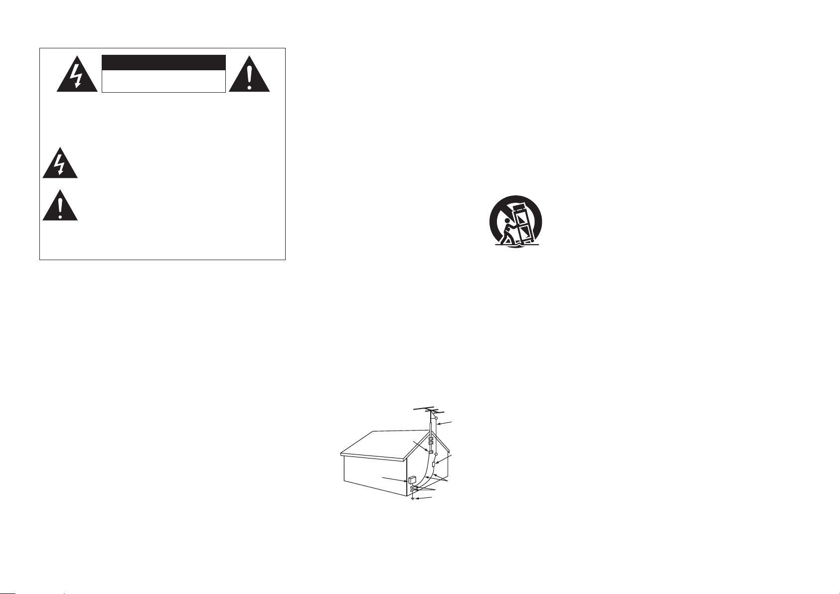
15. Outdoor Antenna Grounding – If an outside antenna or cable system is
connected to the product, be sure the antenna or cable system is grounded
so as to provide some protection against voltage surges and built-up static
charges. Article 810 of the National Electrical Code, ANSI/NFPA 70, provides
information with regard to proper grounding of the mast and supporting
structure, grounding of the lead-in wire to an antenna discharge unit, size
of grounding conductors, location of antenna-discharge unit, connection to
grounding electrodes, and requirements for the grounding electrode. See
Figure A.
16. Lightning – For added protection for this product during a lightning storm,
or when it is left unattended and unused for long periods of time, unplug it
from the wall outlet and disconnect the antenna or cable system. This will
prevent damage to the product due to lightning and power-line surges.
17. Power Lines – An outside antenna system should not be located in the
vicinity of overhead power lines or other electric light or power circuits, or
where it can fall into such power lines or circuits. When installing an outside
antenna system, extreme care should be taken to keep from touching such
power lines or circuits as contact with them might be fatal.
18. Overloading – Do not overload wall outlets, extension cords, or integral
convenience receptacles as this can result in a risk of fire or electric shock.
19. Object and Liquid Entry – Never push objects of any kind into this product
through openings as they may touch dangerous voltage points or short-out
parts that could result in a fire or electric shock. Never spill liquid of any kind
on the product.
20. Ser vicing – Do not attempt to service this product yourself as opening or
removing covers may expose you to dangerous voltage or other hazards.
Refer all servicing to qualified service personnel.
21. Damage Requiring Service – Unplug this product from the wall outlet
and refer servicing to qualified service personnel under the following
conditions:
a) When the power-supply cord or plug is damaged,
b) If liquid has been spilled, or objects have fallen into the product,
c) If the product has been exposed to rain or water,
d) If the product does not operate normally by following the operating
instructions. Adjust only those controls that are covered by the operating
instructions as an improper adjustment of other controls may result in
damage and will often require extensive work by a qualified technician to
restore the product to its normal operation,
e) If the product has been dropped or damaged in any way, and
f) When the product exhibits a distinct change in performance – this
indicates a need for service.
22. Replacement Parts – When replacement parts are required, be sure the
service technician has used replacement parts specified by the manufacturer
or have the same characteristics as the original part. Unauthorized
substitutions may result in fire, electric shock, or other hazards.
23. Safety Check – Upon completion of any service or repairs to this product,
ask the service technician to perform safety checks to determine that the
product is in proper operating condition.
24. Wall or Ceiling Mounting – The product should be mounted to a wall or
ceiling only as recommended by the manufacturer.
25. Heat – The product should be situated away from heat sources such as
radiators, heat registers, stoves, or other products (including amplifiers) that
produce heat.
FIGURE A
EXAMPL E OF ANTENN A GROUNDING
AS PER NATIONAL
ELECTR ICAL CODE
"/5&//"
-&"%*/
8*3&
(306/%
$-".1
&-&$53* $
4&37*$&
&26*1.& /5
"/5&//"
%*4$)"3 (&6/*5
/&$4&$5 *0/
(306/%* /($0/%6$ 5034
/&$4&$5 *0/
(306/%$- ".14
108&34&3 7*$&(306 /%*/(
&-&$530 %&4:45&.
/&$"35 1"35)
/&$/"5*0 /"-&-&$5 3*$"-$0% &
I
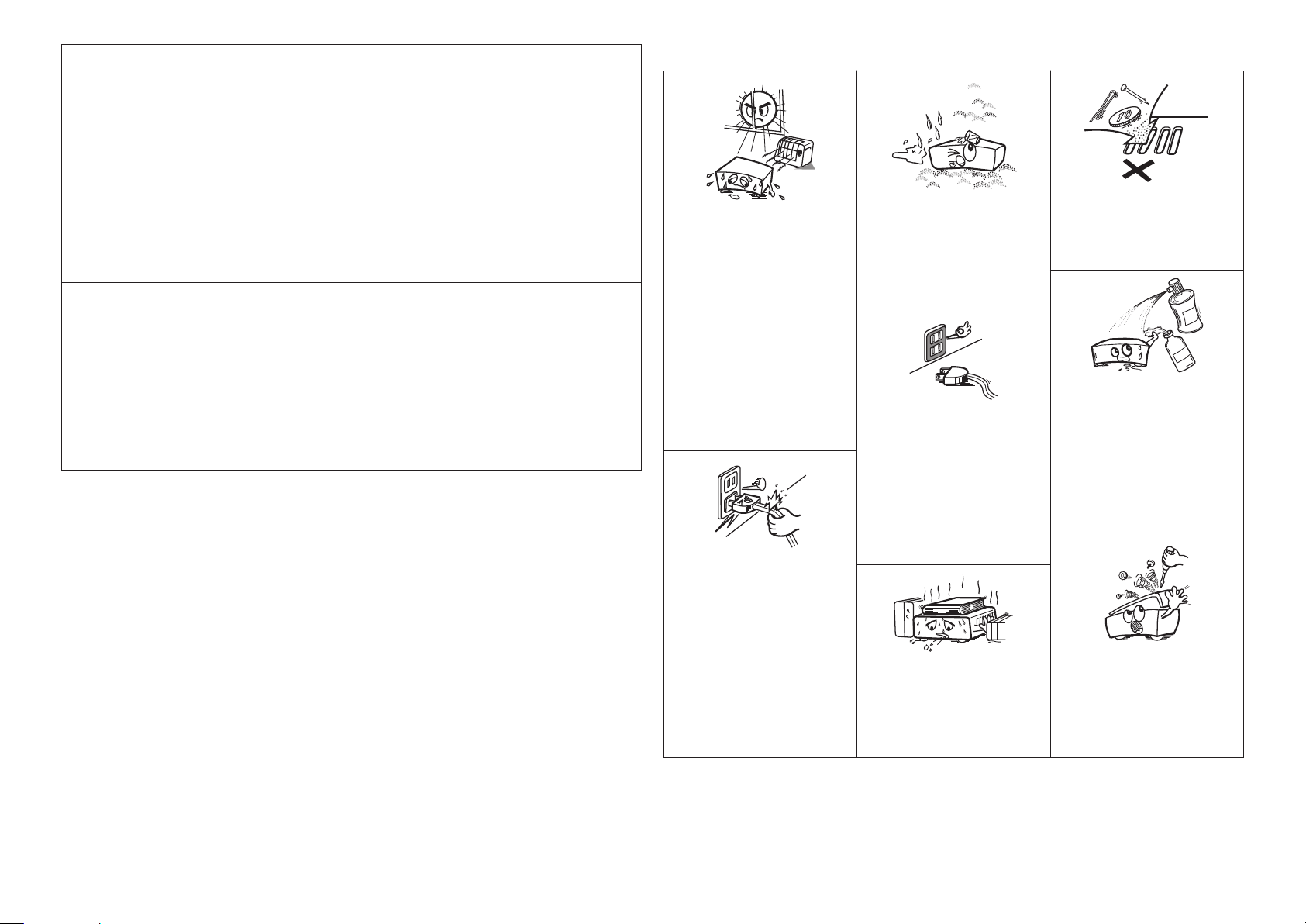
• Avoid high temperatures.
Allow for sufficient heat dispersion when
installed in a rack.
• Eviter des températures élevées.
Tenir compte d’une dispersion de chaleur
suffisante lors de l’installation sur une
étagère.
• Handle the power cord carefully.
Hold the plug when unplugging the cord.
• Manipuler le cordon d’alimentation avec
précaution.
Tenir la prise lors du débranchement du
cordon.
• Keep the unit free from moisture, water,
and dust.
• Protéger l’appareil contre l’humidité, l’eau
et la poussière.
• Unplug the power cord when not using the
unit for long periods of time.
• Débrancher le cordon d’alimentation
lorsque l’appareil n’est pas utilisé pendant
de longues périodes.
* (For apparatuses with ventilation holes)
• Do not obstruct the ventilation holes.
• Ne pas obstruer les trous d’aération.
• Do not let foreign objects into the unit.
• Ne pas laisser des objets étrangers dans
l’appareil.
• Do not let insecticides, benzene, and
thinner come in contact with the unit.
• Ne pas mettre en contact des insecticides,
du benzène et un diluant avec l’appareil.
• Never disassemble or modify the unit in
any way.
• Ne jamais démonter ou modifier l’appareil
d’une manière ou d’une autre.
n
NOTE ON USE / OBSERVATIONS RELATIVES A L’UTILISATION
II
FCC INFORMATION (For US customers)
1. COMPLIANCE INFORMATION
Product Name: AV Surround Receiver
Model Number: AVR-3808CI
This product complies with Part 15 of the FCC Rules. Operation is subject to the following two conditions: (1) this
product may not cause harmful interference, and (2) this product must accept any interference received, including
interference that may cause undesired operation.
Denon Electronics (USA), LLC
(a D & M Holdings Company)
100 Corporate Drive
Mahwah, NJ 07430-2041
Tel. (800) 497-8921
2. IMPORTANT NOTICE: DO NOT MODIFY THIS PRODUCT
This product, when installed as indicated in the instructions contained in this manual, meets FCC requirements.
Modification not expressly approved by DENON may void your authority, granted by the FCC, to use the product.
3. NOTE
This product has been tested and found to comply with the limits for a Class B digital device, pursuant to Part 15
of the FCC Rules. These limits are designed to provide reasonable protection against harmful interference in a
residential installation.
This product generates, uses and can radiate radio frequency energy and, if not installed and used in accordance
with the instructions, may cause harmful interference to radio communications. However, there is no guarantee
that interference will not occur in a particular installation. If this product does cause harmful interference to radio or
television reception, which can be determined by turning the product OFF and ON, the user is encouraged to try to
correct the interference by one or more of the following measures:
• Reorient or relocate the receiving antenna.
• Increase the separation between the equipment and receiver.
• Connect the product into an outlet on a circuit different from that to which the receiver is connected.
• Consult the local retailer authorized to distribute this type of product or an experienced radio/TV technician for
help.
This Class B digital apparatus complies with Canadian ICES-003.
Cet appareil numérique de la classe B est conforme à la norme NMB-003 du Canada.
Accessories ······················································································2
Cautions on Handling ····································································· 3
Cautions on Installation ·································································3
About the Remote Control Unit ····················································3
Inserting the Batteries ····································································3
Operating Range of the Remote Control Unit ································ 3
Part Names and Functions ·····························································4
Front Panel ····················································································· 4
Display ···························································································4
Rear Panel ······················································································5
Remote Control Unit ······································································ 6
Getting Started
Preparations ····················································································7
Cables Used for Connections ························································7
Video Conversion Function ····························································· 8
Speaker Connections ·····································································9
Speaker Installation ········································································9
Speaker Connections ······························································· 9, 10
Connecting Equipment with HDMI connectors ························· 11
Connecting the Monitor ······························································· 12
Connecting the Playback Components ······································ 12
DVD Player ··················································································· 12
Record Player ··············································································· 13
CD Player ····················································································· 13
iPod
®
···························································································· 13
TV/CABLE Tuner ··········································································· 14
Satellite Receiver ········································································· 14
Connecting the Recording Components ···································· 15
Digital Video Recorder ·································································· 15
Video Cassette Recorder ····························································· 15
CD Recorder / MD Recorder / Tape Deck ····································· 16
Connections to Other Devices ····················································· 16
Components Equipped with a DENON LINK connector ·············· 16
Video Camera / Game Console ···················································· 17
Component with Multi-channel Output connectors ····················· 17
External Power Amplifier ······························································ 17
USB Port ······················································································ 18
XM connector ··············································································18
Antenna terminals ······································································· 19
Network Audio ············································································· 20
Multi Zone ····················································································21
External Controller ·······································································21
Connecting the Power Cord·························································22
Once Connections are Completed ··············································22
Connections
Preparations ··················································································25
Auto Setup ····················································································26
a Auto Setup ·············································································· 26
Error Messages ······································································· 27
s
Option ····················································································· 27
d
Parameter Check ·····································································27
Auto Setup
Input Source Selection ··························································· 36, 37
Settings Related to Playing Input Sources ································· 37
a
Play ·························································································
37
s
Auto Preset ·············································································
37
d
Preset Skip ··············································································
37
f
Preset Name ···········································································
37
g
Input Mode ········································································37, 38
h
Rename ··················································································· 38
j
Other ·······················································································38
k
Playback Mode (iPod) ······························································38
l
Assign ····················································································· 39
A0
Playback Mode ········································································ 39
A1
Antenna Aiming ······································································40
Source Select
d
Source Delete ·········································································
34
f
GUI ··························································································
34
g
Quick Select Name ·································································
34
h
Trigger Out 1 ··········································································· 35
j
Trigger Out 2 ··········································································· 35
k
Remote ID ··············································································· 35
l
2Way Remote ········································································· 35
A0
Dimmer ··················································································· 35
A1
Setup Lock ··············································································35
A2
Maintenance Mode ·································································35
A3
Firmware Update ···································································· 36
Language ·······················································································36
Audio······························································································41
a
Surround Parameters ······················································41 ~ 43
s
Tone ························································································43
d
Room EQ ················································································43
f
RESTORER ··············································································43
g
Night Mode ············································································· 44
h
Audio Delay ·············································································44
Picture Adjust ················································································ 44
a
Contrast ··················································································44
s
Brightness ···············································································44
d
Chroma Level ··········································································44
f
Hue ·························································································44
Parameter
Contents
Speaker Setup···············································································28
a
Speaker Configuration ····························································· 28
s
Subwoofer Mode ···································································· 28
d
Distance ·················································································· 28
f
Channel Level··········································································29
g
Crossover Frequency ······························································29
h
Surround Speaker ···································································29
HDMI Setup ···················································································30
a
i/p Scaler ·················································································30
s
Resolution ···············································································30
d
Progressive Mode ···································································30
f
Aspect ·····················································································30
g
Color Space ·············································································30
h
RGB Range ·············································································30
j
Auto Lip Sync ··········································································30
k
Audio ·······················································································30
Audio Setup ··················································································30
a
EXT. IN Setup ··········································································
30
s
2ch Direct/Stereo ····································································
31
d
Downmix Option ·····································································
31
f
Auto Surround Mode ······························································
31
g
Manual EQ ·············································································· 31
Network Setup ··············································································31
a
Network Setup ········································································32
s
Other ·······················································································32
d
Network Information ·······························································32
Zone Setup ····················································································33
a
ZONE2 ····················································································33
s
ZONE3 ····················································································33
Option Setup ················································································· 33
a
Amp Assign ·············································································
33
s
Volume Control ·······································································
34
Manual Setup
Standard Playback ········································································ 40
Surround Playback of 2-channel Sources ·····································40
Playing Multi-channel Sources (Dolby Digital, DTS, etc.) ·············40
DSP Simulation Playback·····························································41
Stereo Playback ············································································41
Direct Playback ·············································································41
Playback in the Pure Direct Mode ················································ 41
Surround Modes
Example of the Display of the GUI Mark at a Title·····················23
Example of Display of Default Values ········································· 23
Examples of GUI Screen Displays ···············································23
Example: Browse Menu (Top Menu)············································ 23
Example: Menus with Illustrations (Auto Setup) ·························· 23
Cursor Position Display ································································ 23
Operations ····················································································· 23
GUI Menu Map ·············································································· 24
GUI Menu Operations
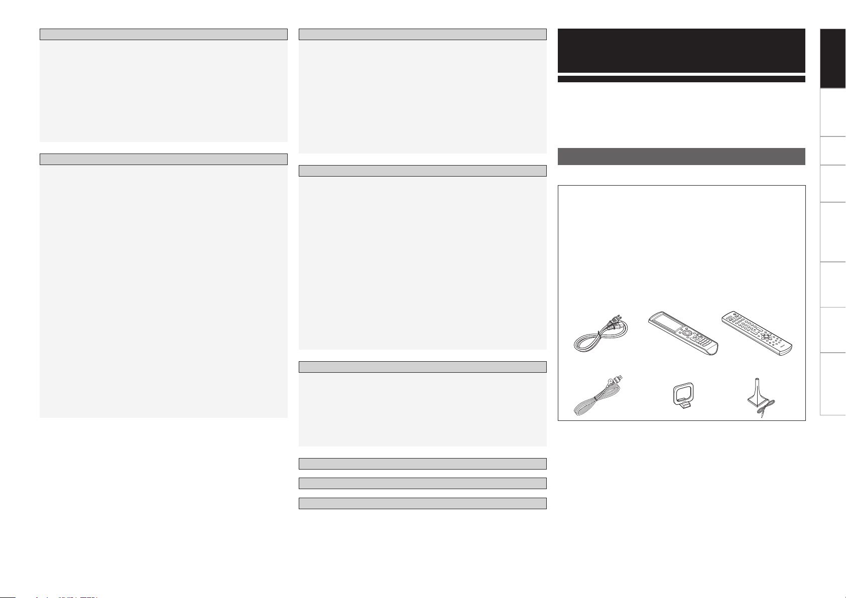
Check that the following parts are supplied with the product.
q Owner’s manual ...................................................................... 1
w Warranty (for North America model only) ................................ 1
e Service station list ...................................................................1
r Power cord (Cord length: Approx. 5 ft /1.5 m) .......................... 1
t Main remote control (RC-1068) ............................................... 1
y LR6/AA batteries (for RC-1068) ................................................ 2
u Sub remote control (RC-1070) ................................................. 1
i R03/AAA batteries (for RC-1070) .............................................2
o FM indoor antenna ..................................................................1
Q0 AM loop antenna ..................................................................... 1
Q1 Setup microphone (Cord length: Approx. 25 ft / 7.6 m) ............ 1
r t u
Q1
o
Q0
Thank you for purchasing this DENON product. To ensure proper
operation, please read this owner’s manual carefully before using the
product.
After reading them, be sure to keep them for future reference.
Getting Started
Accessories
Getting Started Connections Setup Playback Remote Control Multi-Zone Information Troubleshooting
Status ····························································································44
a
MAIN ZONE ············································································ 44
s
ZONE2/3 ·················································································44
Audio Input Signal ········································································ 45
HDMI Information ·········································································45
a
Signal Information ··································································· 45
s
Monitor ···················································································45
Auto Surround ··············································································
45
Quick Select ··················································································
45
Preset Station ···············································································
45
Information
Preparations ··················································································46
Turning the Power On ··································································46
Operations During Playback ·························································46
Playing Video and Audio Equipment ···········································46
Listening to FM/AM Broadcasts ·················································47
Basic Operation ············································································ 47
Presetting Radio Stations (Preset Memory) ································· 47
Listening to Preset Stations ·························································48
Listening to XM Satellite Radio Programs ·································48
Basic Operation ············································································ 48
Checking the XM Signal Strength and Radio ID ··························· 49
Searching Categories ··································································· 49
Accessing XM Radio Stations Directly ·········································49
iPod
®
Playback ············································································· 50
Basic Operation ············································································ 50
Listening to Music ·······································································50
Viewing Still Pictures or Videos on the iPod ································· 50
Playing Network Audio or USB Memory Devices ······················51
Basic Operation ············································································ 52
Listening to Internet Radio ····················································· 52, 53
Presetting Internet Radio Stations ··············································· 53
Registering Internet Radio Stations as Your Favorites ··················53
Playing Files Stored on a Computer ·············································54
Playing Files Stored on USB Memory Devices ···························· 54
Operating the AVR-3808CI Using a Browser (Web control) ·········55
Playback
Main Remote Control Unit···························································59
Operating DENON Audio Components ········································ 59
Presetting ····················································································· 59
Operating Preset Components ············································59 ~ 61
Setting the Remote ID ································································· 62
Learning Function ·········································································62
System Call Function ···································································· 63
Punch Through Function ·······························································63
Setting the Time the Backlight Stays Lit ······································· 63
Adjusting the Backlight’s Brightness ············································64
Resetting the Main Remote Control Unit ·····································64
Sub Remote Control Unit Operations ··································65, 66
Switching Zones ···········································································67
Setting the Zone for Which the Sub Remote Control Unit is Used
(ZONE SELECT LOCK Mode) ······················································· 67
Setting the Remote ID ································································· 67
Resetting the Settings ·································································· 67
Remote Control Unit Operations
Multi-Zone Settings with the Amp Assign Function ···········68, 69
Multi-Zone Settings and Operations with Zone Pre-out Output ···70
Multi-Zone Operations ·································································71
Turning the Power On and Off······················································71
Selecting the Input Source ··························································· 71
Adjusting the Volume ··································································· 71
Turning off the Sound Temporarily ················································71
Amp Assign / Multi Zone Connections and Operations
Troubleshooting ···································································82 ~ 85
Specifications ··············································································· 86
Other Information ································································ 72 ~ 81
Other Operations ··········································································55
Playing Super Audio CDs ·····························································55
Recording on an External Device (REC OUT mode) ·····················56
Convenient Functions ··································································56
Channel Level ···············································································56
Fader Function ·············································································56
Quick Select Function ··································································57
Personal Memory Plus Function ·················································· 57
Last Function Memory ·································································57
Backup Memory ··········································································· 57
Resetting the Microprocessor ······················································58
Other Operations and Functions
List of preset codes ··········································· End of this manual
In addition to the AVR-3808CI, the included main remote control unit
(RC-1068) can also be used to operate the equipment listed below.
q DENON system components
w Non-DENON system components
• By setting the preset memory (vpage 59 ~ 61)
• By using the learn function (vpage 62)
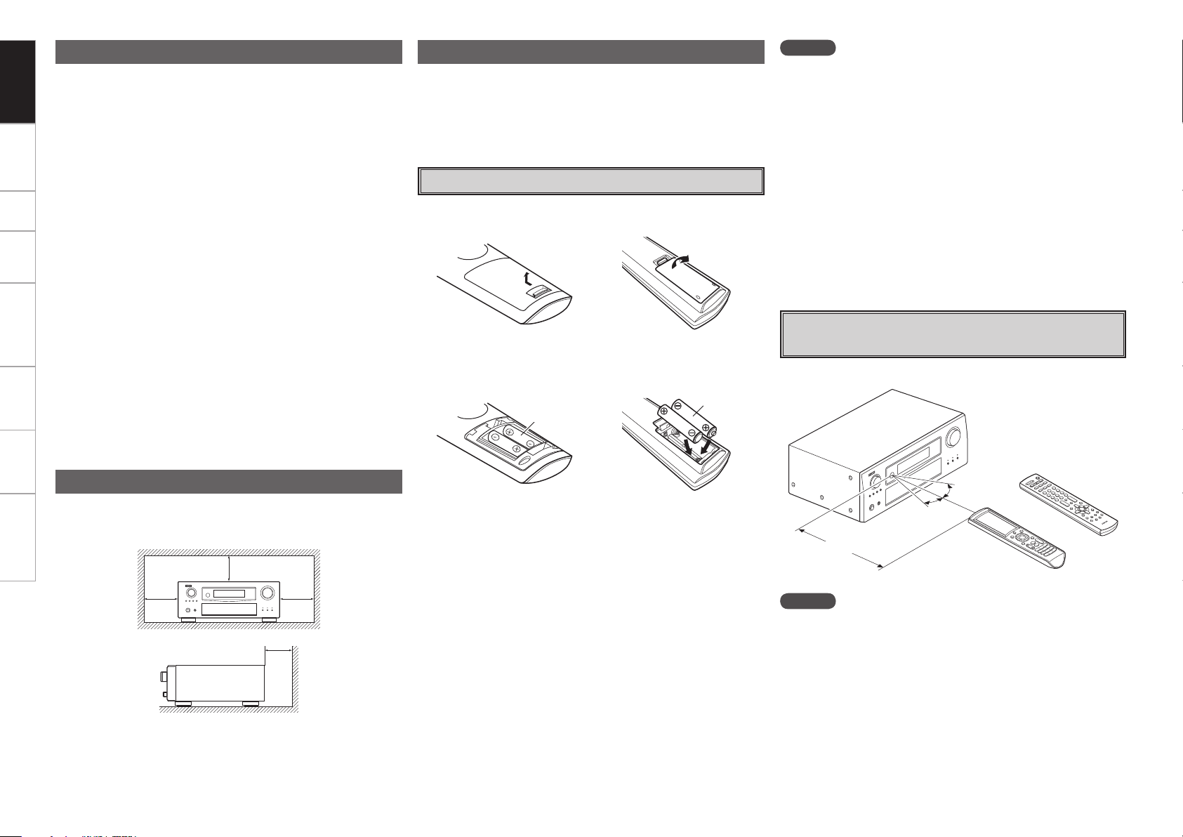
q Lift the clasp and remove the rear lid.
e Put the rear cover back on.
(RC-1068) (RC-1070)
(RC-1068) (RC-1070)
LR6/AA
R03/AAA
30°
30°
Approx. 23 feet / 7 m
or
(RC-1068)
(RC-1070)
w Load the two batteries properly as indicated by the marks in the
battery compartment.
About the Remote Control Unit
Inserting the Batteries
NOTE
• Replace the batteries with new ones if the set does not operate even
when the remote control unit is operated close to the unit.
• The supplied batteries are only for verifying operation.
• When inserting the batteries, be sure to do so in the proper direction,
following the “q” and “w” marks in the battery compartment.
• To prevent damage or leakage of battery fluid:
• Do not use a new battery together with an old one.
• Do not use two different types of batteries.
• Do not attempt to charge dry batteries.
• Do not short-circuit, disassemble, heat or dispose of batteries in
flames.
• If the battery fluid should leak, carefully wipe the fluid off the inside
of the battery compartment and insert new batteries.
• Remove the batteries from the remote control unit if it will not be in
use for long periods.
• When replacing the batteries, have the new batteries ready and
insert them as quickly as possible.
Operating Range of the Remote Control
Unit
Point the remote control unit at the remote sensor when operating it.
NOTE
The set may function improperly or the remote control unit may not
operate if the remote control sensor is exposed to direct sunlight,
strong artificial light from an inverter type fluorescent lamp or infrared
light.
• Before turning the power switch on
Check once again that all connections are correct and that there are
no problems with the connection cables.
•
Power is supplied to some of the circuitry even when the unit is
set to the standby mode. When traveling or leaving home for long
periods of time, be sure to unplug the power cord from the power
outlet.
• About condensation
If there is a major difference in temperature between the inside of
the unit and the surroundings, condensation (dew) may form on
the operating parts inside the unit, causing the unit not to operate
properly.
If this happens, let the unit sit for an hour or two with the power
turned off and wait until there is little difference in temperature
before using the unit.
• Cautions on using mobile phones
Using a mobile phone near this unit may result in noise. If so, move
the mobile phone away from this unit when it is in use.
• Moving the unit
Turn off the power and unplug the power cord from the power
outlet.
Next, disconnect the connection cables to other system units before
moving the unit.
•
Note that the illustrations in these instructions may differ from the
actual unit for explanation purposes.
Note:
For proper heat dispersal, do not install this unit in a confined
space, such as a bookcase or similar enclosure.
b Note
b
Wall
b
b
Cautions on Handling
Cautions on Installation
Getting Started Connections Setup Playback Remote Control Multi-Zone Information Troubleshooting
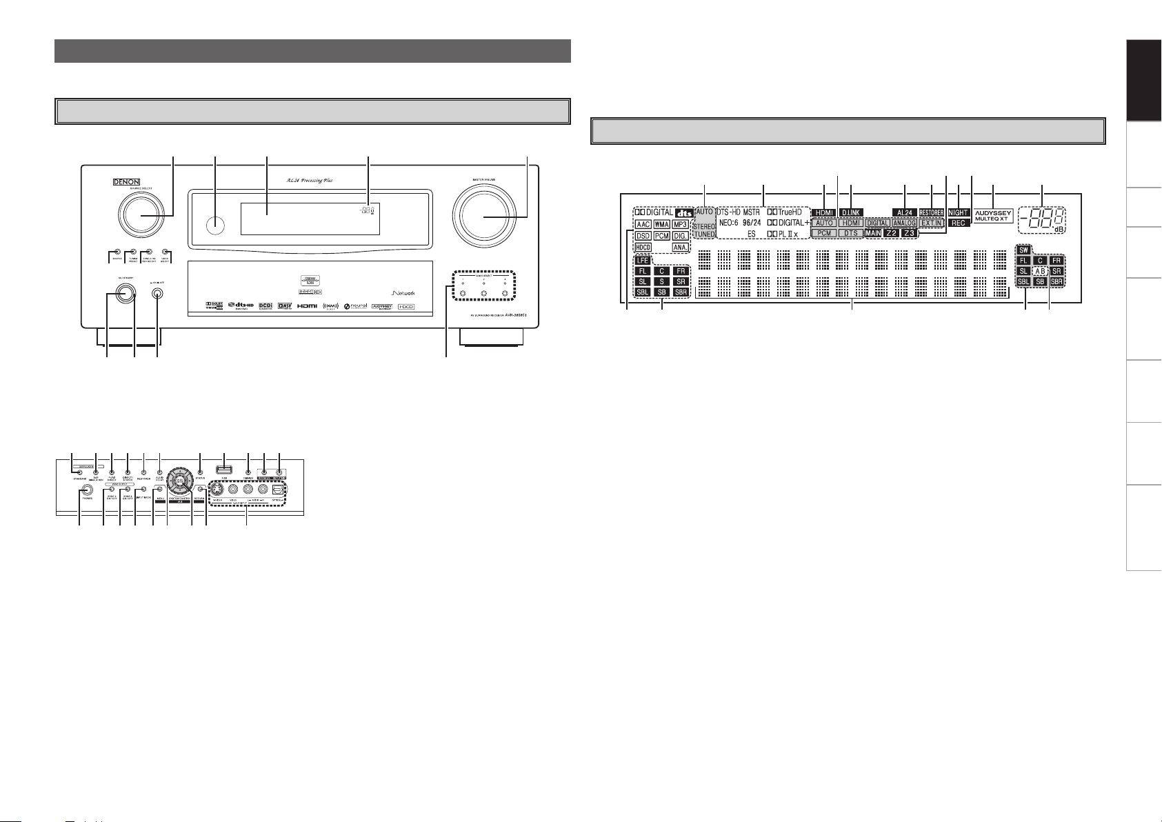
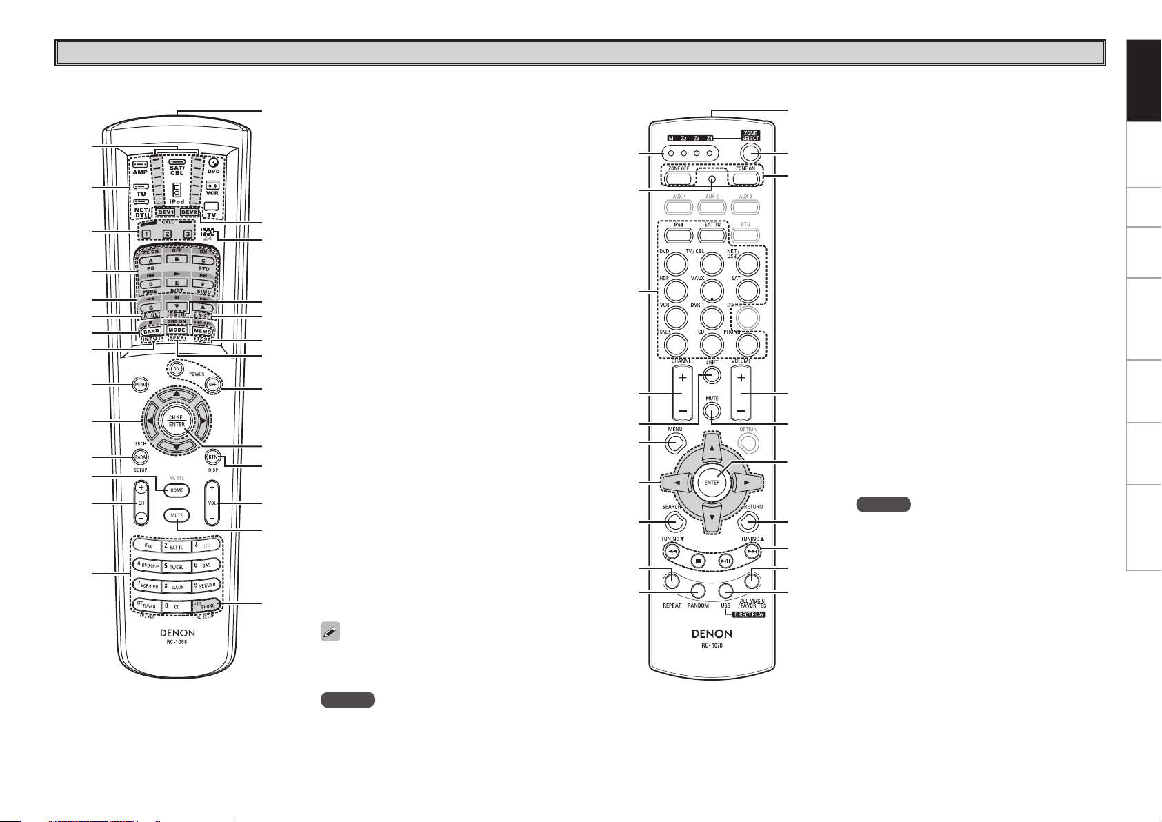
For buttons not explained here, see the page indicated in parentheses ( ).
w e
to i u y
q r
Q3Q2Q1Q0
q Power operation button
(ON/STANDBY) ···········································(46)
w Power indicator ··········································· (46)
e Power switch (hON jOFF) ····················· (46)
r QUICK SELECT buttons / indicators ········· (57)
t MASTER VOLUME control knob ················ (46)
y Master volume indicator
u Display
i Remote control sensor ································· (3)
o SOURCE SELECT knob······························· (36)
Q0 SOURCE button ·········································· (36)
Q1 TUNING PRESET button ···························· (48)
Q2 ZONE2/3 / REC SELECT button ··········(56, 71)
Q3 VIDEO SELECT button ·······························(38)
Q4 Headphones jack (PHONES) ······················ (46)
Q5 ZONE2 ON/OFF button ······························ (71)
Q6 ZONE3 ON/OFF button ······························ (71)
Q7 INPUT MODE button ·································· (38)
Q8 MENU button ·············································· (23)
Q9 Cursor buttons (uio p) ·························· (23)
W0 CH SEL / ENTER button ······················· (23, 56)
W1 RETURN button ·········································· (23)
W2 V.AUX INPUT connectors ··························· (17)
W3 SETUP MIC jack ·········································· (25)
W4 ROOM EQ button ········································ (43)
W5 DIMMER button ·········································· (35)
t
yQ6Q7 uo
iQ4 Q0
Q1Q2Q3Q5
wq e r
q Input signal indicators
w Input signal channel indicators
These light when digital signals are input.
e Information display
The input source name, surround mode, setting
values and other information are displayed here.
r Output signal channel indicators
t Surround speaker indicators
These light according to the settings of the
surround A and B speakers.
y Master volume indicator
u AUDYSSEY MULTEQ XT indicator
This lights when the room equalizer is selected.
i Recording output source indicator
This lights when the REC OUT mode is
selected.
o NIGHT indicator
This lights when the night mode is selected.
Q0 Multi zone indicators
These light when the power for the respective
zone is turned on.
Q1 RESTORER indicator
This lights when the RESTORER mode is
selected.
Q2 AL24 indicator
This lights when AL24 Processing Plus is
activated (vpage 74).
Q3 D.LINK indicator
This lights when playing using DENON LINK
connections.
Q4 Input mode indicators
Q5 HDMI indicator
This lights when playing using HDMI
connections.
Q6 Decoder indicators
These light when the respective decoders are
operating.
Q7 Tuner reception mode indicators
These light according to the reception conditions
when the input source is set to “TUNER”.
• AUTO
These light when in the auto tuning mode.
• STEREO
In the FM mode, these light when receiving
analog stereo broadcasts.
• TUNED
Lights when the broadcast is properly tuned in.
Part Names and Functions
Front Panel
Display
W3W4W5W7W8W9E0E1E2E3 W6
Q4 Q5 Q6 Q8 W1W0Q7 W2Q9
GWith the door openG
E0 DIRECT/STEREO button·····························(41)
E1 PURE DIRECT button ·································· (41)
E2 DSP SIMULATION button ·························· (41)
E3 STANDARD button ·····································(40)
W6 USB port ······················································ (18)
W7 STATUS button ···········································(45)
W8 AUDIO DELAY button ································· (44)
W9 RESTORER button ······································ (43)
Getting Started Connections Setup Playback Remote Control Multi-Zone Information Troubleshooting
Q7 Q8 Q8Q9 Q7 W0
y
r
Q0Q1Q2Q3
Q6
oQ4Q5
q w e iu
t
Q7 Q8 Q8Q9 Q7 W0
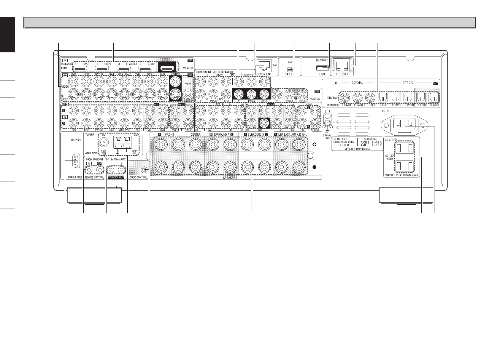
q RS-232C connector ····································· (21)
w REMOTE CONTROL jacks···························(21)
e TRIGGER OUT jacks ···································(21)
r FM/AM antenna terminals
(TUNER ANTENNA) ···································· (19)
t DOCK CONTROL jack ································· (13)
y Speaker terminals (SPEAKERS) ·················· (9)
u AC OUTLETS ··············································· (22)
i AC inlet (AC IN) ··········································· (22)
o Digital audio connectors
(OPTICAL / COAXIAL) ·························· (12, 14)
Q0 ETHERNET connector ································· (20)
Q1 USB port ······················································ (18)
Q2 XM connector (SAT TU) ······························ (18)
Q3 DENON LINK connector ····························· (16)
Q4 COMPONENT VIDEO connectors ·············· (12)
Q5 HDMI connectors ·········································(11)
Q6 VIDEO / S-VIDEO connectors ···················· (12)
Q7 Analog audio connectors (AUDIO) ············ (12)
Q8 PRE OUT connectors ····························· (17, 21)
Q9 EXT. IN connectors ····································· (17)
W0 SIGNAL GND terminal ······························· (13)
Rear Panel
Getting Started Connections Setup Playback Remote Control Multi-Zone Information Troubleshooting
q
i
w
e
r
t
y
u
o
Q1
Q3
Q4
Q2
Q0
Q5
Q6
Q7
Q9
W0
W2
W5
W7
W6
W4
W3
W1
Q8
q Signal transmission indicator ···················(59)
w Mode select buttons ··································(59)
e Quick select / System call buttons ······(57, 63)
r Surround mode buttons ······················ (40, 41)
t System buttons ···································· (60, 61)
y Audio delay button (A. DL) ························(44)
u Tuner system buttons ································ (47)
i Input mode button (INPUT) ······················· (38)
o MENU button ·············································· (23)
Q0 Cursor buttons (uio p) ························· (23)
Q1 Parameter / Search button
(PARA / SRCH) ································ (41, 49, 50)
Q2 HOME button ·············································· (59)
Q3 Channel buttons (CH) ································· (47)
Q4 Input source select / Number buttons ·· (36, 47)
Q5 Remote control signal transmitter ·············· (3)
Q6 Device select indicators (DEV1 / DEV2) ···(59)
Q7 ZONE3 select indicators (Z3) ····················· (71)
Q8 RESTORER button (RSTR) ·························· (43)
Q9 Night button (NGT) ···································· (44)
W0 Test tone button (TEST) ····························· (29)
W1 Surround speaker select button (SPKR) ··· (29)
W2 POWER buttons ·········································· (46)
W3 Channel select (CH SEL) /
ENTER button ······································· (23, 56)
W4 Return button (RTN) ··································· (23)
W5 Master volume control buttons (VOL) ······(46)
W6 Muting button (MUTE) ························· (46, 71)
W7 Main remote control unit setup button
(RC SETUP) ················································· (59)
q
r
t
y
i
o
Q0
u
e
w
Q4
Q7
Q8
Q6
Q5
Q2
Q3
Q1
Q9
W0
q ZONE indicators·········································· (67)
w Advanced setup button ······························ (67)
e Input source select buttons ······················· (36)
r CHANNEL buttons ······································ (47)
t SHIFT button ··············································· (47)
y MENU button ·············································· (23)
u Cursor buttons (uio p) ························· (23)
i SEARCH button ····································(49, 50)
o REPEAT button ············································ (50)
Q0 RANDOM button ········································(50)
Q1 Remote control signal transmitter ·············· (3)
Q2 ZONE SELECT button ································· (67)
Q3 Zone power on/off buttons
(ZONE ON / ZONE OFF) ····························· (71)
Q4 Master volume control buttons
(VOLUME) ············································(65, 66)
Q5 Muting button (MUTE) ························· (46, 71)
Q6 ENTER button ············································· (23)
Q7 RETURN button ·········································· (23)
Q8 System buttons ····································· (47, 65)
Q9 ALL MUSIC/FAVORITES
(DIRECT PLAY) button ······························· (65)
W0 USB (DIRECT PLAY) button························ (65)
n Main remote control unit (RC-1068) n Sub remote control unit (RC-1070)
The time for which the backlight stays on can
be changed (vpage 63 “Setting the Time the
Backlight Stays Lit”).
Remote Control Unit
NOTE
• The M. SEL, DTU buttons cannot be used.
• The ZONE2 mode QUICK SELECT (1 ~ 3), A.DL,
RSTR, NGT, INPUT, SPKR, TEST and surround
mode buttons cannot be used.
• The ZONE4 mode cannot be used.
NOTE
The AUX-1, AUX-2, AUX-3, DTU, DVR-2 and OPTION
buttons cannot be used.
Getting Started Connections Setup Playback Remote Control Multi-Zone Information Troubleshooting
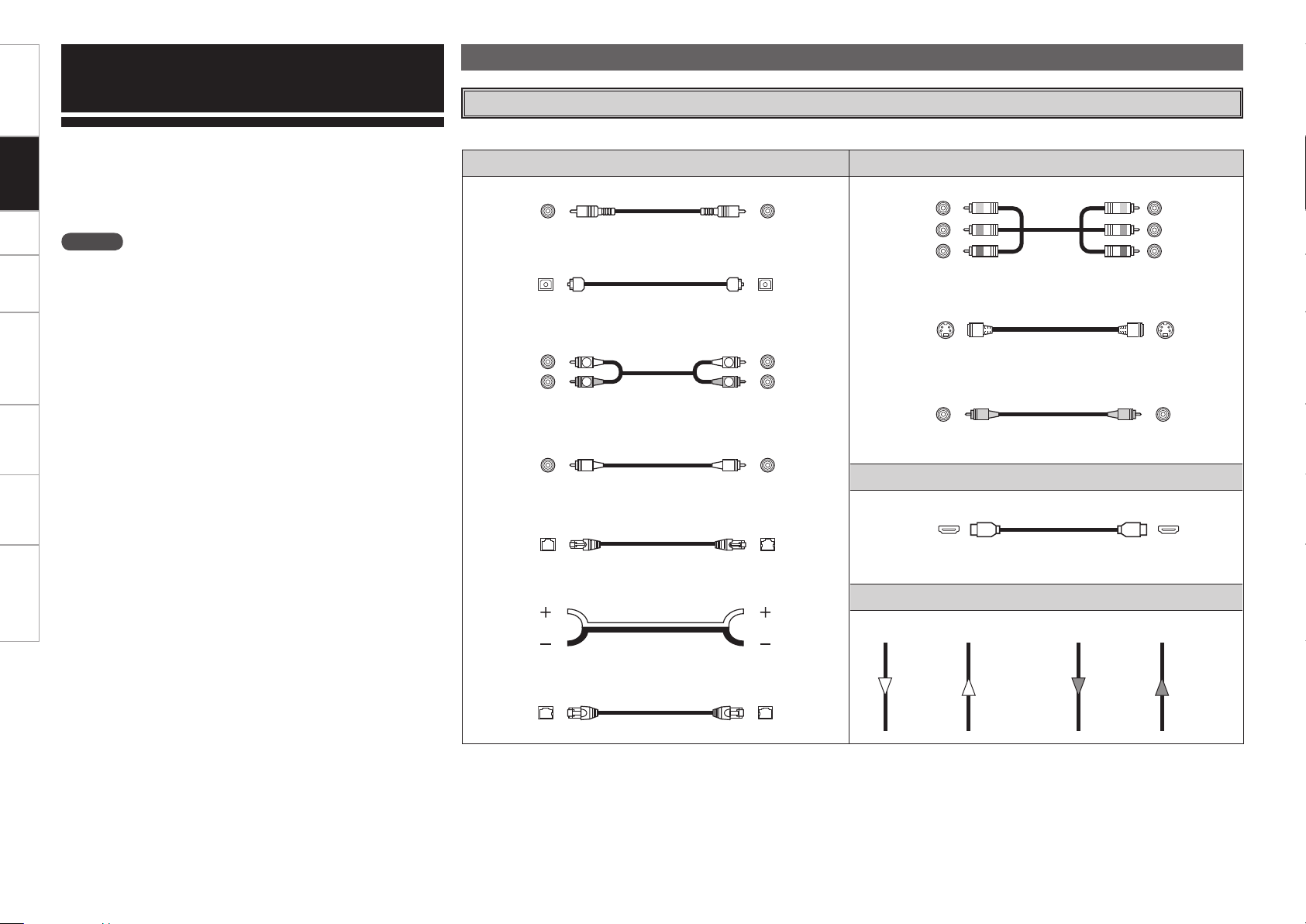
Audio cables Video cables
Coaxial digital connections
(Orange)
Coaxial digital (75 Ω/ohms pin-plug) cable
Optical digital connections
Optical cable
Analog connections (stereo)
(White)
(Red)
R
L
R
L
Stereo pin-plug cable
Analog connections (monaural, for subwoofer)
(Black)
Pin-plug cable
DENON LINK connections
DENON LINK cable
Speaker connections
Speaker cables
Network connections
Ethernet cable
Component video connections
(Green)
(Blue)
(Red)
(Y)
(PB/CB)
(PR/CR)
Component video cable
S-Video connections
S-Video cable
Video connections
(Yellow)
75 Ω/ohms pin-plug video cable
Audio and video cables
HDMI connections
19-pin HDMI cable
Signal direction
Audio signal: Video signal:
Output
Input
Input
Output
Output
Input
Input
Output
Connections
NOTE
• Do not plug in the power cord until all connections have been
completed.
• When making connections, also refer to the operating instructions of
the other components.
• Be sure to connect the left and right channels properly (left with left,
right with right).
• Do not bundle power cords together with connection cables. Doing
so can result in humming or noise.
Connections for all compatible audio and video signal formats are
described in these operating instructions. Please select the types
of connections suited for the equipment you are connecting.
With some types of connections, certain settings must be made
on the AVR-3808CI. For details, refer to the instructions for the
respective connection items below.
Cables Used for Connections
Select the cables according to the equipment being connected.
Getting Started Connections Setup Playback Remote Control Multi-Zone Information Troubleshooting
Preparations
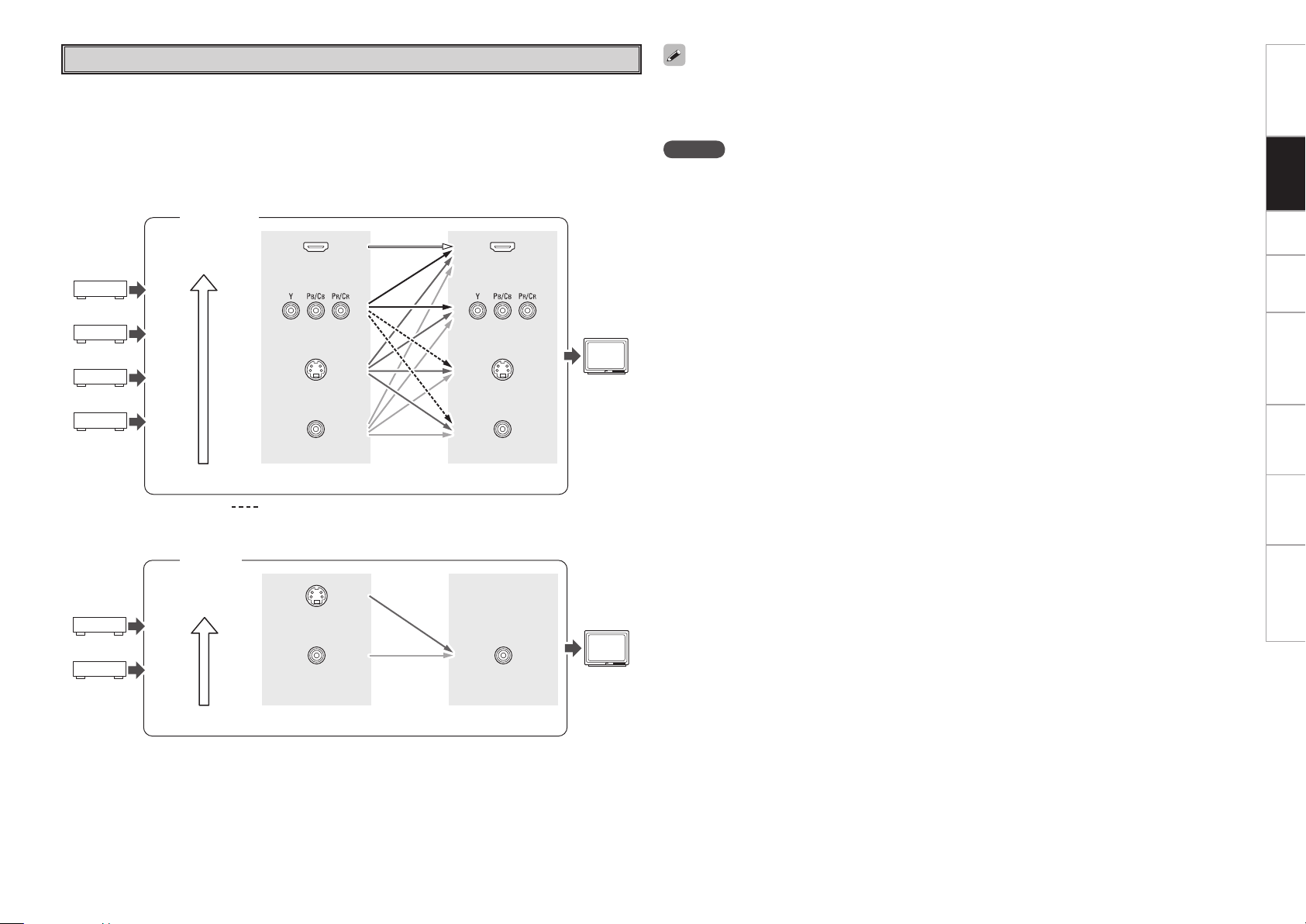
GFlow of video signals for ZONE2G
• This function automatically converts various formats of video signals input to the AVR-3808CI into the
format used to output the video signals from the AVR-3808CI to a monitor.
• The AVR-3808CI’s video input/output circuitry is compatible with the following four types of video
signals:
Digital video signals: HDMI
Analog video signals: Component video, S-Video and Video
Video Conversion Function
GFlow of video signals inside the AVR-3808CIG
Main zone
High picture
quality playback
HDMI connector
Component video
connectors
S-Video connector
Video connector
Monitor
HDMI connector
Component video
connectors
S-Video connector
Video connector
Video inputs Video outputs
: When 480i/576i signals are input in the main zone
S-Video connector
Video connector Video connector
Video inputs Video outputs
ZONE2
NOTE
• HDMI signals cannot be converted into analog signals.
• 1080p component input video signals cannot be output to anything other than component video
connectors.
• 480p/576p, 1080i and 720p component video input signals cannot be converted into S-Video or Video
format.
• When a non-standard video signal from a game machine or some other source is input, the video
conversion function might not operate.
• When not using this function, connect a monitor output with the same type of connector as the video
input connector.
• The resolution of the HDMI input-compatible monitor connected to the AVR-3808CI can be checked at
GUI menu “Information” – “HDMI Information” – “Monitor” (vpage 45).
High picture
quality playback
ZONE2
monitor
Getting Started Connections Setup Playback Remote Control Multi-Zone Information Troubleshooting
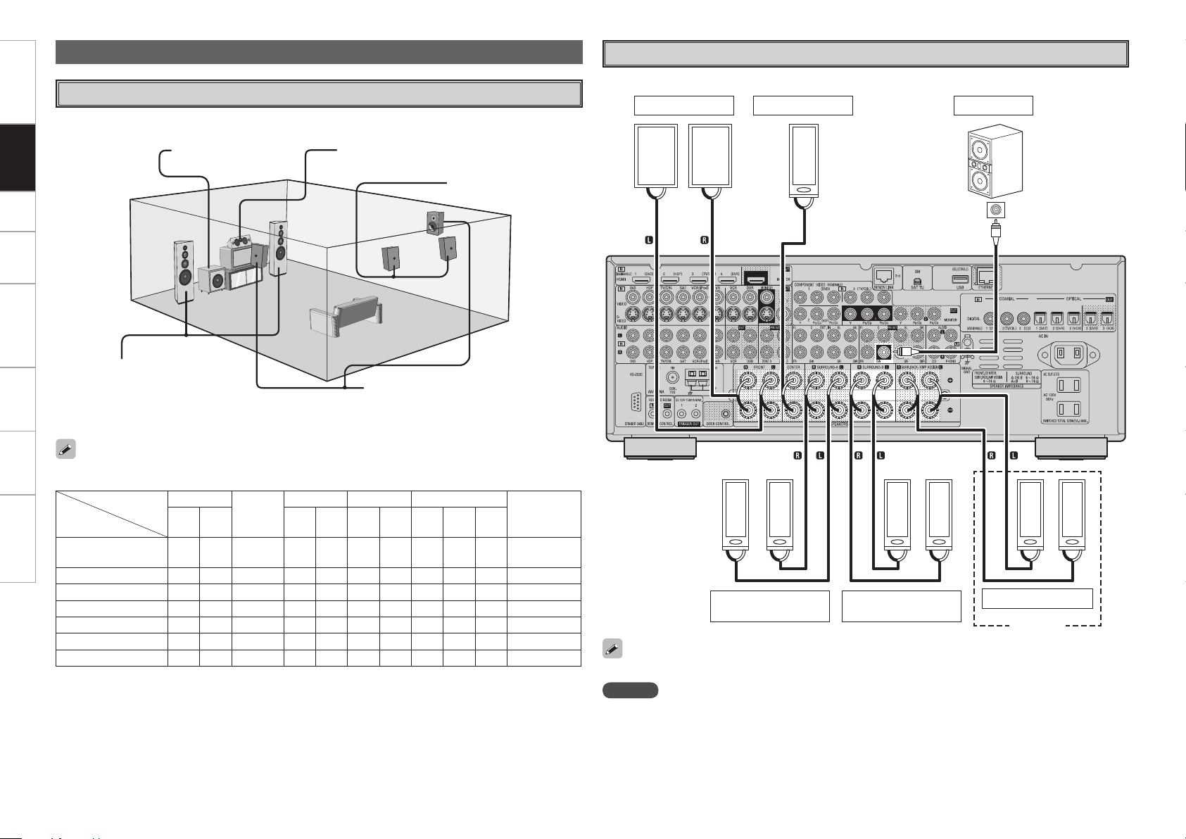
Speaker Connections
w q
w q
w q w q w q w q w q w q
*/
w q
(R)
(L) (R) (L) (R)
(L)
(L) (R)
The illustration below shows a basic example of installation of the amplifier combined with 8 speakers and
a monitor.
Speaker Installation
Subwoofer Center speaker
Surround speakers
Front speakers
Place the front speakers to the
sides of the monitor or screen and
as flush with the screen surface as
possible.
The table below shows a typical speaker configuration for the AVR-3808CI.
Surround back speakers
Front
Center
Surround A Surround B Surround back
Subwoofer
L R L R L R L R
1
only
7.1-channels
(Surround A+B)
S S S S S S S S S
–
S
7.1-channels
S S S S S
– –
S S
–
S
6.1-channels
S S S S S
– – – –
S S
5.1-channels
S S S S S
– – – – –
S
3.1-channels
S S S
– – – – – – –
S
2.1-channels
S S
– – – – – – – –
S
2-channels
S S
– – – – – – – – –
Speaker Connections
Example: 5.1-channels (Surround A+B) and ZONE2 use
Front speakers Center speaker Subwoofer
Subwoofer
with built-in
amplifier
Surround speakers
A
Surround speakers
B
ZONE2 speakers
ZONE2
When using just one surround back speaker, connect it to the left channel (SBL).
NOTE
By default, the AVR-3808CI’s “Amp Assign” setting is set to “ZONE2”. To use as the surround back speaker
for the main zone, change the “Amp Assign” setting (vpage 68, 69).
b L : Left
R : Right
Getting Started Connections Setup Playback Remote Control Multi-Zone Information Troubleshooting
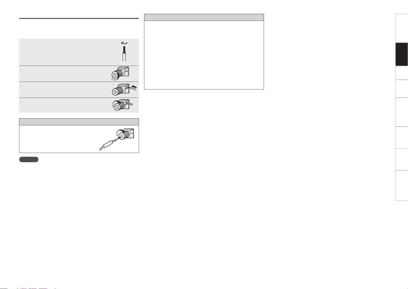
Connecting the Speaker Cables
Carefully check the left (L) and right (R) channels and + (red) and –
(black) polarities on the speakers being connected to the AVR-3808CI,
and be sure to interconnect the channels and polarities correctly.
1
Peel off about 0.03 ft/10 mm of sheathing
from the tip of the speaker cable, then
either twist the core wire tightly or
terminate it.
2
Turn the speaker terminal
counterclockwise to loosen it.
3
Insert the speaker cable’s core wire to
the hilt into the speaker terminal.
4
Turn the speaker terminal clockwise to
tighten it.
When using a banana plug
Tighten the speaker terminal firmly before
inserting the banana plug.
NOTE
• Use speakers with an impedance of 6 to 16 Ω/ohms. When using
surround A and B speakers simultaneously, use speakers with an
impedance of 8 to 16 Ω/ohms.
• Connect the speaker cables in such a way that they do not stick out
of the speaker terminals. The protection circuit may be activated if
the core wires touch the rear panel or if the + and – sides touch each
other (v “Protection circuit”).
• Never touch the speaker terminals while the power supply is
connected. Doing so could result in electric shock.
Protection circuit
If speakers with an impedance lower than specified (for example
4 Ω/ohms speakers) are used for an extended period of time with
the volume turned up high, the temperature may rise, activating the
protection circuit.
When the protection circuit is activated, the speaker output is shut
off and the power indicator flashes red. If this happens, unplug
the power cord, then check the speaker cable and input cable
connections. If the set is extremely hot, wait for it to cool off and
improve ventilation around it. Once this is done, plug the power cord
back in and turn the set's power back on.
If the protection circuit is activated again even though there are no
problems in the ventilation around the set nor in the connections,
the set may be damaged. Turn the power off, then contact a DENON
service center.
0
Getting Started Connections Setup Playback Remote Control Multi-Zone Information Troubleshooting
Getting Started Connections Setup Playback Remote Control Multi-Zone Information Troubleshooting
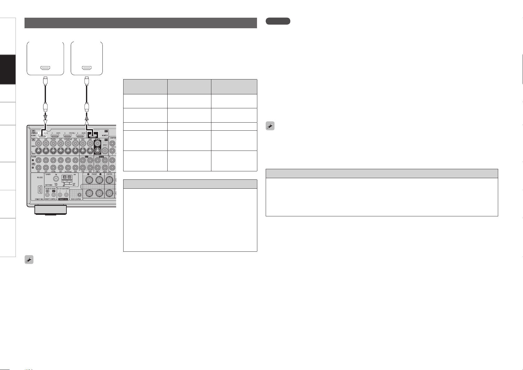
With HDMI connections, the video and audio signals can be transferred with a single cable.
065
)%.*
*/
)%.*
Compatible
audio format
Details
Discs
(examples)
2-channel linear
PCM
2ch 32-192 kHz
16/20/24 bits
CD, DVD-Video,
DVD-Audio
Multi-channel
linear PCM
8ch 32-192 kHz
16/20/24 bits
DVD-Audio
Dolby Digital, DTS Bitstream DVD-Video
DSD
2/5.1ch
2.8224 MHz
1 bit
SACD
Dolby Digital Plus,
Dolby TrueHD,
DTS-HD
Bitstream
HD DVD,
Blu-ray Disc
MonitorDVD player
b The AVR-3808CI is equipped for HDMI version 1.3a.
This version is compatible with other versions, allowing
connection to all components equipped with an HDMI
connector.
b The AVR-3808CI is compatible with 30- and 36-bit Deep
Color.
Copyright protection system (HDCP)
In order to play the digital video and audio signals of a DVD-
Video or DVD-Audio disc using HDMI/DVI connections, both
the connected DVD player and monitor must be equipped
for a copyright protection system called “HDCP” (High-
bandwidth Digital Content Protection).
HDCP is a copy protection technology consisting of data
encoding and mutual identification of the devices.
The AVR-3808CI is HDCP-compatible. For details on the
DVD player or monitor you are using, refer to its operating
instructions.
• When the AVR-3808CI and DVD player are connected using an HDMI cable, also connect the AVR-3808CI
and monitor using an HDMI cable.
• If the connected monitor or DVD player only has a DVI-D connector, use an HDMI/DVI converter cable.
When using a DVI cable, no audio signals are transmitted.
• Use a Deep Color compatible cable for connection to Deep Color compatible devices.
When connecting with an HDMI/DVI converter cable (adapter)
• HDMI video signals are theoretically compatible with the DVI format.
When connecting to a monitor, etc., equipped with a DVI-D connector, connection is possible using an
HDMI/DVI converter cable, but depending on the combination of components in some cases the video
signals will not be output.
• When connecting using an HDMI/DVI converter adapter, the video signals may not be output properly
due to poor connections with the connected cable, etc.
• By default, the HDMI audio signals are output from the speakers connected to the AVR-3808CI.
• To output the sound from the TV, make the settings at GUI menu “Manual Setup” – “HDMI Setup”
– “Audio” – “TV” (vpage 30).
NOTE
• Use a CPPM-compatible DVD player to play DVD-Audio discs that are copyright-protected by CPPM.
• The AVR-3808CI cannot be controlled from another device via the HDMI cable.
• The audio signals output from the HDMI connector (sampling frequency, bit rate, etc.) may be restricted
by the connected device.
• Video signals are not output properly when using devices that are not HDCP-compatible.
• Video signals are not output if the input video signals do not match the monitor’s resolution. In this case,
switch the DVD player’s resolution to a resolution with which the monitor is compatible.
• If the GUI menu “Manual Setup” – “HDMI Setup” – “Audio” setting (vpage 30) is set to “Amp”, the
sound may be interrupted when the monitor’s power is turned off.
• Use a cable on which the HDMI logo is indicated (a certified HDMI product) for connection to the HDMI
connector. Normal playback may not be possible when using a cable other than one on which the HDMI
logo is indicated (a non-HDMI-certified product).
• If the monitor or DVD player does not support deep color, deep color signal transfer is not possible.
• If the monitor or DVD player does not support xvYCC, xvYCC signal transfer is not possible.
• If the monitor does not support “Auto Lipsync Correction” function, this function will not work.
Connecting Equipment with HDMI connectors
Getting Started Connections Setup Playback Remote Control Multi-Zone Information Troubleshooting
• Connect the cables to be used (vpage 8 “Video Conversion Function”).
• With HDMI connections, the video and audio signals can be transferred with a single cable.
• To output the audio signals to the monitor with HDMI connections, set GUI menu “Manual Setup”
– “HDMI Setup” – “Audio” to “TV” (vpage 30).
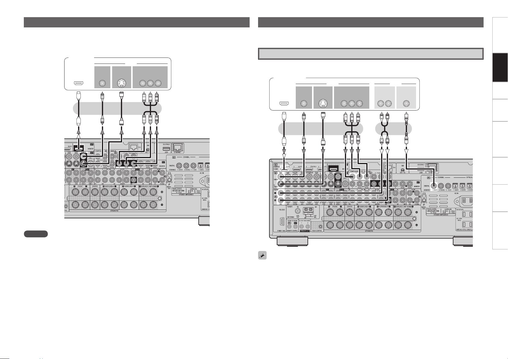
Connecting the Monitor
47*%&0
*/
7*%&0
$0.10/&/57*%&0
: 1# 13
7*%&0
*/
)%.*
*/ */
47*%&0
065
"6%*07*%&0
$0.10/&/57*%&0
: 1# 13
7*%&0
065 065
"6%*0
$0"9*"-
065
3-
065065
)%.*
R
L
R
L
Monitor
Carefully check the left (L) and right (R) channels and the inputs and outputs, and be sure to interconnect
correctly.
Connecting the Playback Components
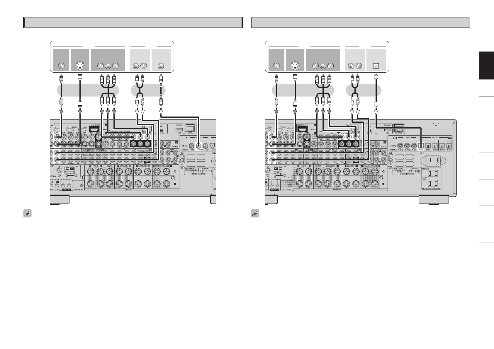
DVD Player
• Connect the cables to be used.
• With HDMI connections, the video and audio signals can be transferred with a single cable.
DVD player
NOTE
• The component video connectors may be indicated differently on your monitor. For details, see the
monitor’s operating instructions.
• The audio signals output from the HDMI connectors are only the HDMI input signals.
• Connect an HDP (High-Definition Player) in the same way.
• When using an optical cable for the digital audio connection, make the settings at GUI menu “Source
Select” – “DVD” – “Assign” – “Digital” (vpage 39).
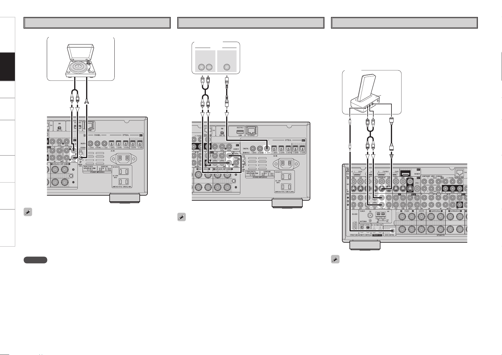
Record Player
• When connecting a record player with an MC cartridge, use a
commercially available MC head amplifier or a step-up transformer.
• Induction humming (a booming sound) may be produced from the
speakers if the volume is raised with no record player connected.
• With some record players, noise may be generated when the ground
wire is connected. If so, disconnect the ground wire.
(/%
"6%*0
065
R
L
Turntable (MM cartridge)
NOTE
The AVR-3808CI’s SIGNAL GND terminal is meant to reduce noise
when a record player is connected. This is not a safety ground
terminal.
"6%*0
"6%*0
$0"9*"-
065
3-
065
R
L
R
L
CD Player
Connect the cables to be used.
CD player
iPod
®
Example :
"4%3
R
L
R
L
iPod
When using an optical cable for the digital audio connection, make the
settings at GUI menu “Source Select” – “CD” – “Assign” – “Digital”
(vpage 39).
• With the default settings, the iPod can be used connected to the VCR
(iPod) connector.
• To assign the iPod to a connector other than VCR (iPod), make the
settings at GUI menu “Source Select” – “(input source to which iPod
dock assigned)” – “Assign” – “iPod dock” (vpage 39).
Use a DENON Control Dock for iPod (ASD-1R, sold separately) to
connect the iPod to the AVR-3808CI. For instructions on the Control
Dock for iPod settings, refer to the Control Dock for iPod’s operating
instructions.
or
ConnectionsGetting Started Setup Playback Remote Control Multi-Zone Information Troubleshooting
47*%&0
065
"6%*07*%&0
$0.10/&/57*%&0
: 1# 13
7*%&0
065 065
"6%*0
3-
065
$0"9*"-
065
R
L
R
L
TV/CABLE Tuner
Connect the cables to be used.
TV tuner
When using an optical cable for the digital audio connection, make the settings at GUI menu “Source
Select” – “TV/CBL” – “Assign” – “Digital” (vpage 39).
Satellite Receiver
Connect the cables to be used.
47*%&0
065
"6%*07*%&0
$0.10/&/57*%&0
: 1# 13
7*%&0
065 065 065
015*$"-"6%*0
3-
065
R
L
R
L
DBS / BS tuner
• When using a coaxial digital cable for the digital audio connection, make the settings at GUI menu “Source
Select” – “SAT” – “Assign” – “Digital” (vpage 39).
• When using a component video cable for the video connection, make the settings at GUI menu “Source
Select” – “SAT” – “Assign” – “Component” (vpage 39).
Getting Started Connections Setup Playback Remote Control Multi-Zone Information Troubleshooting
Carefully check the left (L) and right (R) channels and the inputs and outputs, and be sure to interconnect
correctly.
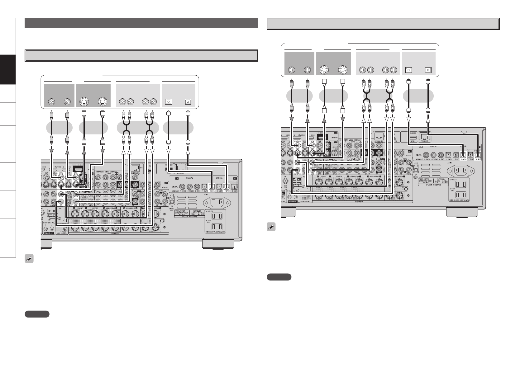
Connecting the Recording Components
Digital Video Recorder
Connect the cables to be used.
47*%&0
*/
3- 3-
*/*/065
"6%*07*%&0
*/065
015*$"-
065
"6%*07*%&0
065
R
L
R
L
R
L
R
L
Digital video recorder
NOTE
Do not connect the output of the component connected to the AVR-3808CI’s OPTICAL2 output connector
to any input connector other than OPTICAL2.
• Make analog connections if you wish to record analog audio signals.
• When recording to a digital video recorder, it is necessary that the type of cable used with the playback
source equipment be the same type that is connected to the AVR-3808CI DVR OUT connector.
Example: TV IN → S-Video cable : DVR OUT → S-Video cable
TV IN → Video cable : DVR OUT → Video cable
• When using a component video cable for the video connection, make the settings at GUI menu “Source
Select” – “DVR” – “Assign” – “Component” (vpage 39).
or or
Getting Started Connections Setup Playback Remote Control Multi-Zone Information Troubleshooting
47*%&0
*/
3- 3-
*/*/065
"6%*07*%&0
065
"6%*07*%&0
065 */065
015*$"-
R
L
R
L
R
L
R
L
Video Cassette Recorder
Connect the cables to be used.
Video cassette recorder
• When recording to a VCR, it is necessary that the type of cable used with the playback source equipment
be the same type that is connected to the AVR-3808CI VCR OUT connector.
Example: TV IN → S-Video cable : VCR OUT → S-Video cable
TV IN → Video cable : VCR OUT → Video cable
• When using a component video cable for the video connection, make the settings at GUI menu “Source
Select” – “VCR” – “Assign” – “Component” (vpage 39).
or
NOTE
Do not connect the output of the component connected to the AVR-3808CI’s OPTICAL3 output connector
to any input connector other than OPTICAL3.
or
3- 3-
065 */065
015*$"-
*/
"6%*0
"6%*0
R
L
R
L
R
L
R
L
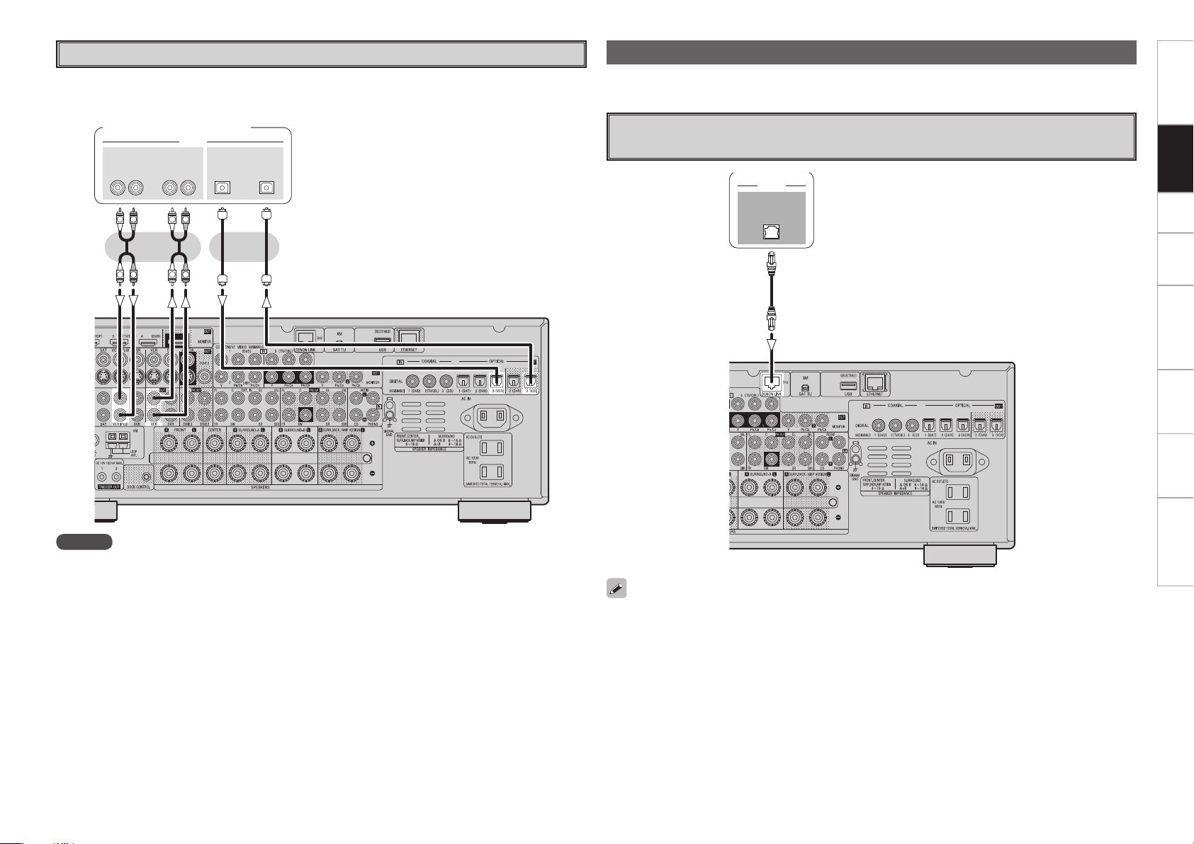
CD Recorder / MD Recorder / Tape Deck
Make analog connections if you wish to record analog audio signals, or digital connections if you wish to
record digital audio signals, depending on the types of connectors on the components being used.
CD recorder /
MD recorder / Tape deck
NOTE
Do not connect the output of the component connected to the AVR-3808CI’s OPTICAL3 output connector
to any input connector other than OPTICAL3.
or
Getting Started Connections Setup Playback Remote Control Multi-Zone Information Troubleshooting
Carefully check the left (L) and right (R) channels and the inputs and outputs, and be sure to interconnect
correctly.
Connections to Other Devices
%&/0/-*/,
"6%*0
Components Equipped with a DENON LINK connector
Multi-channel playback is possible with DVD-Audio discs, Super Audio CD, etc.
DVD player
To use with DENON LINK connections, make the settings at GUI menu “Source Select” – “Assign” –
“Digital” – “DENON LINK” (vpage 39).
47*%&0
065
"6%*07*%&0
7*%&0
065 065
015*$"-"6%*0
3-
065
R
L
R
L
46#
800'&3
$&/5&3 463306/%
#"$,
3-
463306/%
3-
'30/5
3-
"6%*0
R
L
R
L
R
L
R
L
R
L
R
L
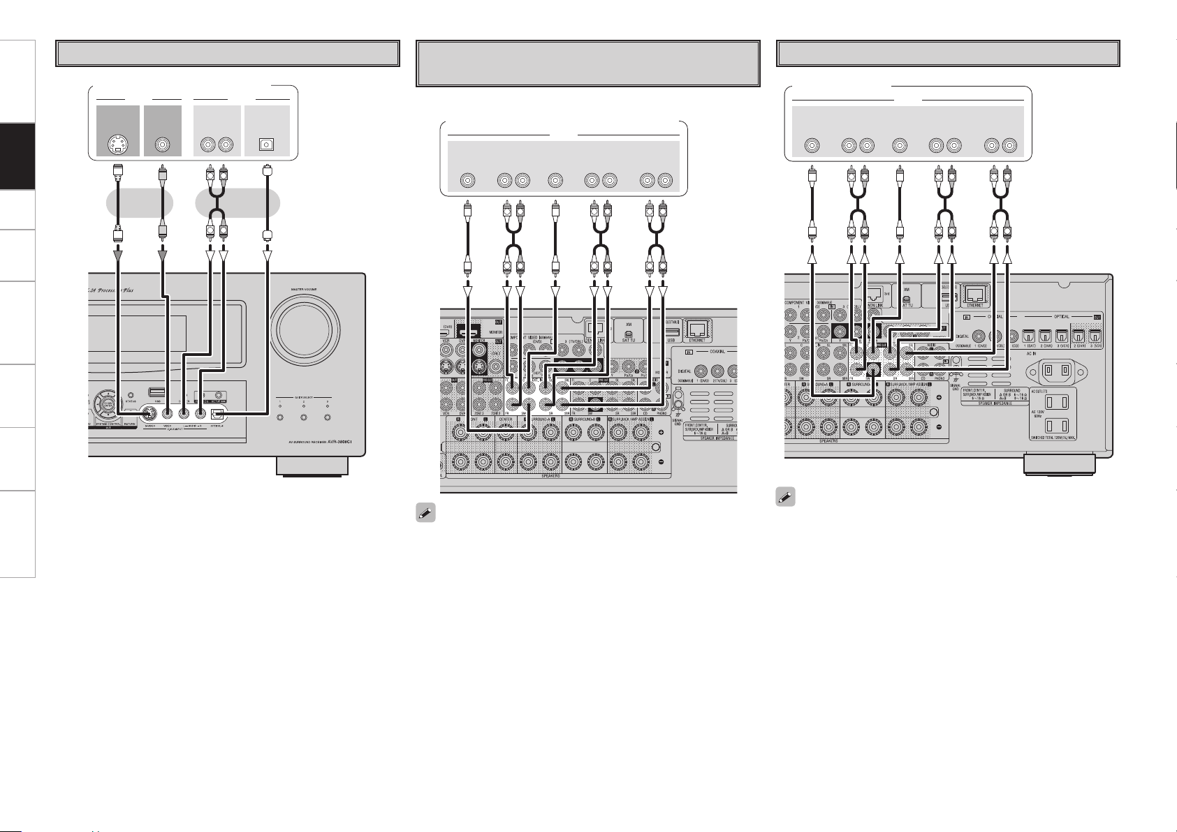
Video Camera / Game Console
Video camera / Game console
Component with Multi-channel Output
connectors
DVD player /
Super Audio CD player / External decoder
• To play the analog input signals input to the EXT. IN connectors,
press the INPUT MODE button on the main unit or INPUT button
on the main remote control unit and select “EXT. IN” or make the
settings at GUI menu “Source Select” – “(input source)” – “Input
Mode” – “Input Mode” – “EXT. IN” (vpage 37).
• The video signal can be connected in the same way as a DVD player
(vpage 12).
• To play copyright-protected discs, connect the AVR-3808CI’s EXT.
IN connector with the DVD player’s analog multi-channel output
connector.
Getting Started Connections Setup Playback Remote Control Multi-Zone Information Troubleshooting
46#
800'&3
$&/5&3 463306/%
#"$,
3-
463306/%
3-
'30/5
3-
"6%*0
R
L
R
L
R
L
R
L
R
L
R
L
External Power Amplifier
When using just one surround back speaker, connect it to the left
channel (SBL).
Power amplifier
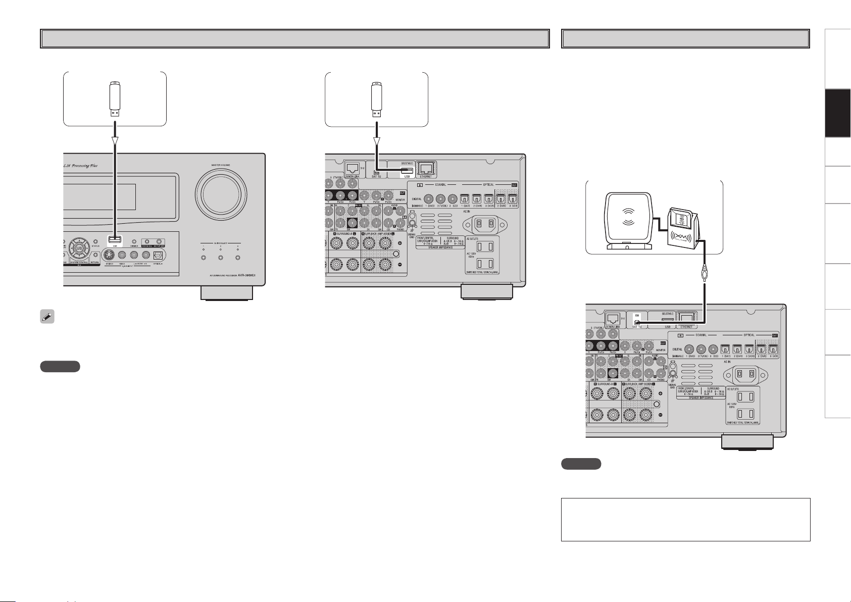
XM
NOTE
Keep the power cord unplugged until the XM Mini-Tuner and Home
Dock connection have been completed.
XM connector
• The AVR-3808CI is an XM Ready
®
receiver. You can receive XM
®
Satellite Radio by connecting to the XM Mini-Tuner and Home Dock
(includes home antenna, sold separately) and subscribing to the XM
service.
• Plug the XM Mini-Tuner and Home Dock into the XM connector on
the rear panel.
• Position the Home Dock antenna near a south-facing window to
receive the best signal.
For details, see “Listening to XM Satellite Radio Programs” (vpage
48, 49).
When making connections, also refer to the operating instructions of
the XM Mini-Tuner and Home Dock.
XM Mini-Tuner and Home Dock
• The XM name and related logo are registered trademarks of XM
Satellite Radio Inc. All rights reserved.
• XM Ready is a registered trademark of XM Satellite Radio Inc. All
rights reserved.
Getting Started Connections Setup Playback Remote Control Multi-Zone Information Troubleshooting
USB Port
• In the initial status, USB memory devices can be used by connecting them to the USB port on the front panel.
• To change the port to be used, see “USB Select” on page 39.
• For instructions on playing the files on a USB memory device, see page 54.
NOTE
• Set to the USB port you want to use.
• The AVR-3808CI is equipped with two USB ports, one each on the front and rear panels. It is not possible to use the set with USB memory
devices connected to both the ports at the same time. Select the USB port you want to use at the “Source Select” – “NET/USB” – “Playback
Mode” – “USB Select” menu.
n Front panel n Rear panel
USB memory device USB memory device
• Do not use the extension cable for connecting the USB memory deveice to the AVR-3808CI’s USB port.
Use of the extension cable may cause harmful interference.
Getting Started Connections Setup Playback Remote Control Multi-Zone Information Troubleshooting
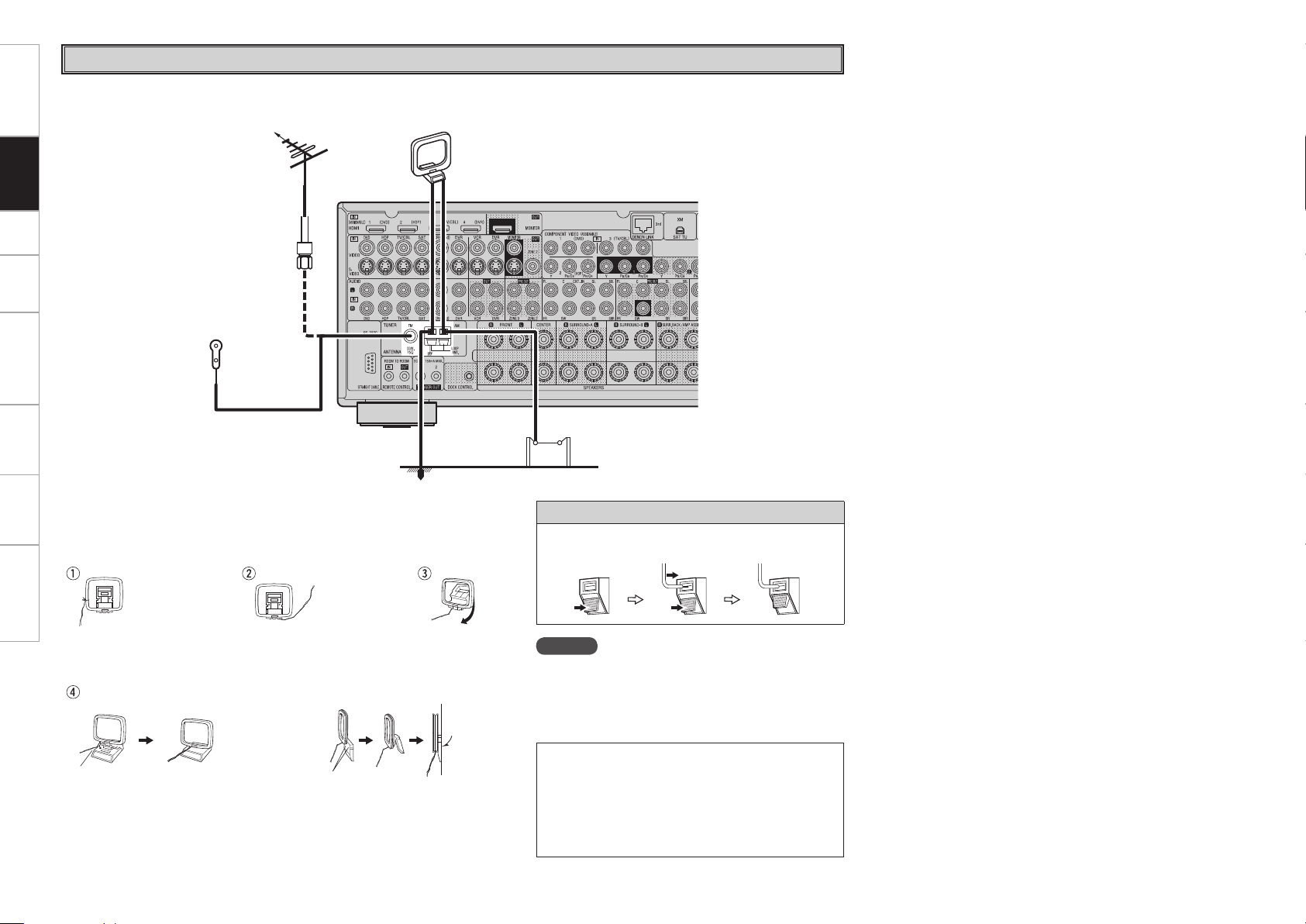
Antenna terminals
An F-type FM antenna cable plug can be connected directly.
Direction of broadcasting station
AM loop antenna
(supplied)
FM antenna
75 Ω/ohms
Coaxial cable
FM indoor antenna
(supplied)
Ground
AM outdoor antenna
Note to CATV system installer:
This reminder is provided to call the CATV system
installer’s attention to Article 820-40 of the NEC
which provides guidelines for proper grounding and,
in particular, specifies that the cable ground shall be
connected to the grounding system of the building,
as close to the point of cable entry as practical.
AM loop antenna assembly
Remove the vinyl tie and take
out the connection line.
Connect to the AM
antenna terminals.
Bend in the reverse direction.
a. With the antenna on top of
any stable surface.
Mount
b. With the antenna attached
to a wall.
Installation hole Mount on wall, etc.
Connection of AM antennas
1. Push the
lever.
2. Insert the
conductor.
3. Return the
lever.
NOTE
• Do not connect two FM antennas simultaneously.
• Even if an external AM antenna is used, do not
disconnect the AM loop antenna.
• Make sure the AM loop antenna lead terminals do not
touch metal parts of the panel.
Getting Started Connections Setup Playback Remote Control Multi-Zone Information Troubleshooting
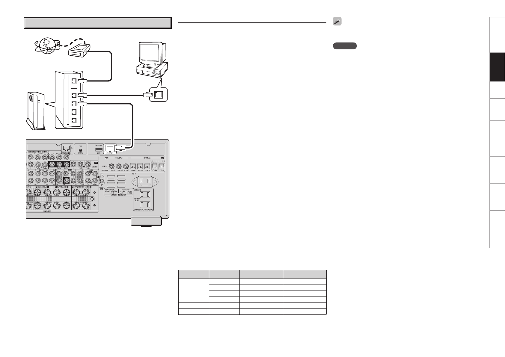
Required system
n Broadband Internet connection
A broadband line connection to the Internet is required in order
to use the AVR-3808CI’s Internet radio function and firmware
update.
n Modem
This is a device that is connected to the broadband line to
communicate with the Internet. Some are integrated with the
router.
n Router
When using the AVR-3808CI, we recommend you use a router
equipped with the following functions:
• Built-in DHCP (Dynamic Host Configuration Protocol) server
This function automatically assigns IP addresses on the LAN.
• Built-in 100 BASE-TX switch
When connecting multiple devices, we recommend a switching
hub with a speed of 100 Mbps or greater.
n Ethernet cable (CAT-5 or greater recommended)
• The AVR-3808CI does not come with an Ethernet cable.
• Some flat type Ethernet cables are easily affected by noise.
We recommend using a normal type cable.
• If the sound is broken in an environment in which there is much
power supply noise from electric products or in a noisy network
environment, use a shielded type Ethernet cable.
n Computer
A computer with the following specifications is required to use a
music server:
• OS
Windows® XP Service Pack2, Windows Vista
• Software (Prepare one of the following.)
· .NET Framework 1.1 and Windows Media Connect (Windows XP)
· Windows Media Player ver.11
· DLNA-compatible server software
• Internet browser
Microsoft Internet Explorer 5.01 or later
• LAN port
• 300 MB or more free disk space
b Free disk space is required to store music files. The following
sizes are approximate.
Format Bit rate Per minute Per hour
MP3 / WMA
MPEG-4 AAC
128 kbps Approx. 1 MB Approx. 60 MB
192 kbps Approx. 1.5 MB Approx. 90 MB
256 kbps Approx. 2 MB Approx. 120 MB
392 kbps Approx. 3 MB Approx. 180 MB
WAV (LPCM)
1400 kbps Approx. 10 MB Approx. 600 MB
FLAC
1080 kbps Approx. 7.7 MB Approx. 464 MB
NOTE
• A contract with an ISP is required to connect to the Internet.
No additional contract is needed if you already have a broadband
connection to the Internet.
• The types of routers that can be used depend on the ISP. Contact an
ISP or a computer shop for details.
• Depending on the server, video files may be displayed, but they
cannot be played on the AVR-3808CI.
For connections to the Internet, contact an ISP (Internet Service
Provider) or a computer shop.
n Others
• If you have an Internet provider contract for a line on which network
settings are made manually, make the settings at GUI menu
“Manual Setup” – “Network Setup” (vpage 32).
• With the AVR-3808CI, it is possible to use the DHCP and Auto IP
functions to make the network settings automatically.
• When using a broadband router (DHCP function), the AVR-3808CI
sets the IP address, etc., automatically.
When using the AVR-3808CI connected to a network with no
DHCP function, make the settings for the IP address, etc., at GUI
menu “Manual Setup” – “Network Setup” (vpage 32).
• The AVR-3808CI is not compatible with PPPoE. A PPPoE-compatible
router is required if you have a contract for a line of the type with
which the PPPoE is set.
• Depending on the ISP with which you have your contract, it may
be necessary to make proxy server settings to use the Internet
radio function. If you made proxy server settings on the computer
to connect to the Internet, make the proxy server settings on the
AVR-3808CI in the same way.
0
Getting Started Connections Setup Playback Remote Control Multi-Zone Information Troubleshooting
Network Audio
To WAN side
Internet
Router
Computer
To LAN port
To LAN port
LAN port/
Ethernet
connector
Modem
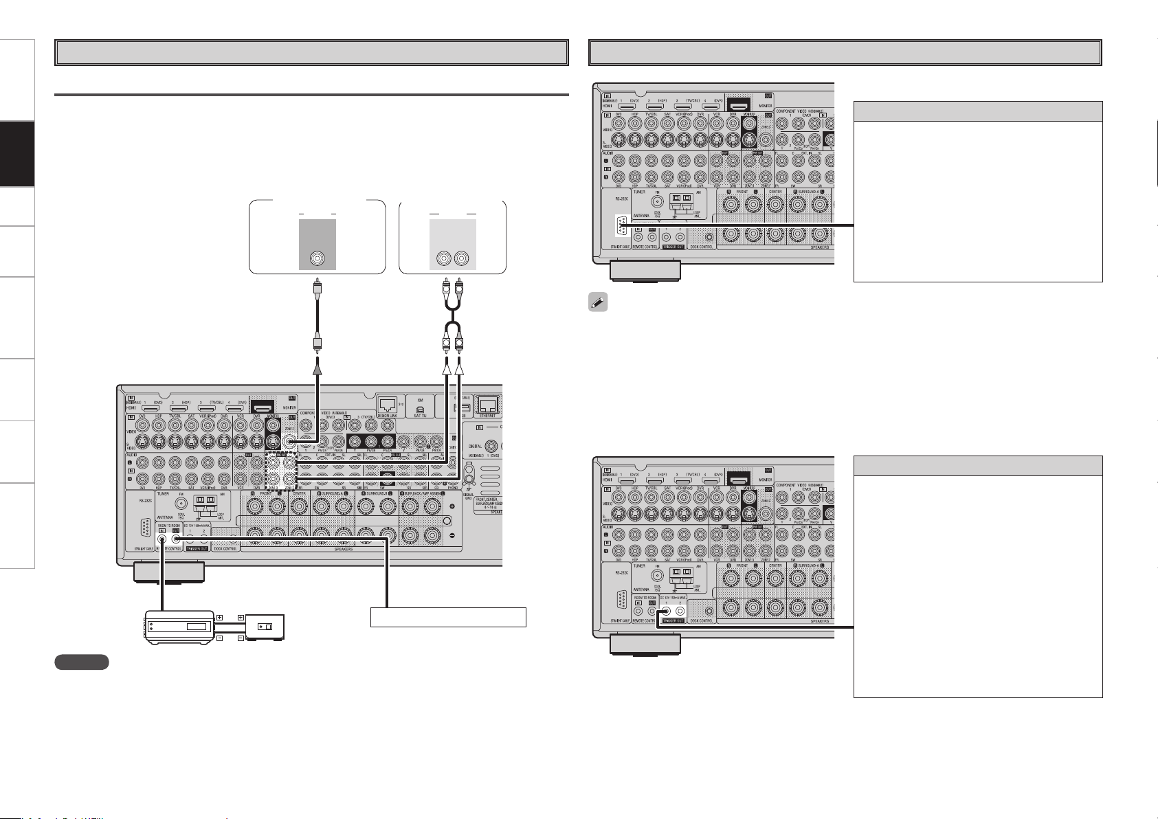
Multi Zone
ZONE2 or ZONE3 Pre-out Connections
• If another power amplifier or pre-main (integrated) amplifier is connected, the ZONE2 or ZONE3 pre-out
(variable or fixed level) connectors can be used to play a different program source in ZONE2 or ZONE3
the same time (vpage 68 ~ 71).
• When using an S-Video cable or a video cable for connection between the AVR-3808CI and an input
device, connect to the video connectors.
• The ZONE2 video out is only for ZONE2.
R
L
R
L
"69
065
"6%*0
3-
*/*/
7*%&0
"6%*07*%&0
Monitor (ZONE2)
Power amplier
(ZONE2 or ZONE3)
Input
Output
Infrared
retransmitter
Infrared
sensor
Extension jack for future use.
NOTE
• For the audio output, use high quality pin-plug cords so that no induction humming or noise is produced.
• For instructions on installing and operating separately sold devices, refer to the respective devices’
operating instructions.
• To conduct multi-zone playback, see “Amp Assign / Multi Zone Connections and Operations” (vpage
68 ~ 71).
Getting Started Connections Setup Playback Remote Control Multi-Zone Information Troubleshooting
External Controller
• When using in combination with an RF Remote Controller (RC-7000CI, sold separately) or RF Remote
Receiver (RC-7001RCI, sold separately) two-way communication with an RF Remote Controller is
possible.
The AVR-3808CI’s status information as well as iPod and Internet audio music files can be browsed
watching the RF Remote Controller’s display. For details, refer to the operating instructions of the
respective devices.
• When used in combination with an RF Remote Controller or RF Remote Receiver, make the settings at
GUI menu “Manual Setup” – “Option Setup” – “2Way Remote” – “Used” (vpage 35).
RS-232C connector
This connector is used for an external controller.
b If you wish to control the AVR-3808CI from
an external controller using the RS-232C
connector, perform the operation below
beforehand.
q Turn the AVR-3808CI’s power.
w Turn off the AVR-3808CI’s power from the
external controller.
e Check that the AVR-3808CI is in the standby
mode.
Trigger output jacks
The power of an external device equipped with
a trigger input jack can be turned on and off in
association with operations on the AVR-3808CI.
For details, see GUI menu “Manual Setup” –
“Option Setup” – “Trigger Out 1” or “Trigger Out
2” (vpage 35).
• Output level: 150 mA/12 V
Check the trigger input conditions of the
connected device.
• If the trigger input level of the connected device
is higher than 150 mA/12 V and depending on
the short-circuiting conditions, the AVR-3808CI’s
protection circuit may be activated, in which case
“TRIGGER PROTECT” appears on the display. If
this happens, turn off the AVR-3808CI’s power
and disconnect the connected device.
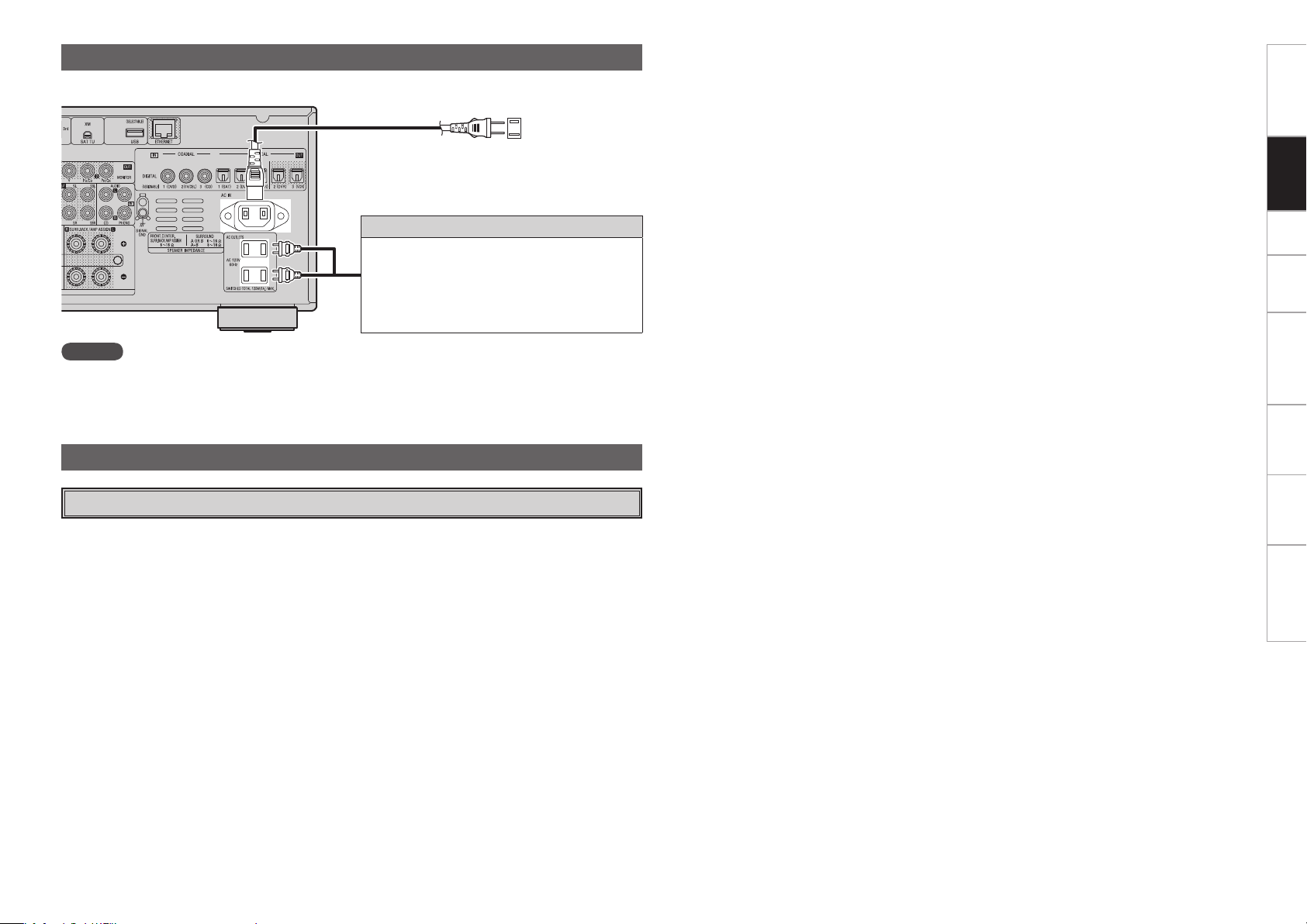
NOTE
• Insert the AC plugs securely. Incomplete connections could cause noise.
• Only use the AC outlets to plug in audio devices. Do not use them as power supplies for hairdryers or
anything other than audio equipment.
Wait until all connections have been completed before connecting the power cord.
To household
power outlet
(AC 120 V, 60 Hz)
Power cord
(included)
Connection to the AC outlets
• These outlets supply power to external audio
devices.
• The power supplied from these outlets turns on
and off together with the set’s power switch.
• Audio equipment with a total power consumption
of 120 W (1 A) can be connected.
Connecting the Power Cord
Turning the Power On (vpage 46)
Once Connections are Completed
Getting Started Connections Setup Playback Remote Control Multi-Zone Information Troubleshooting
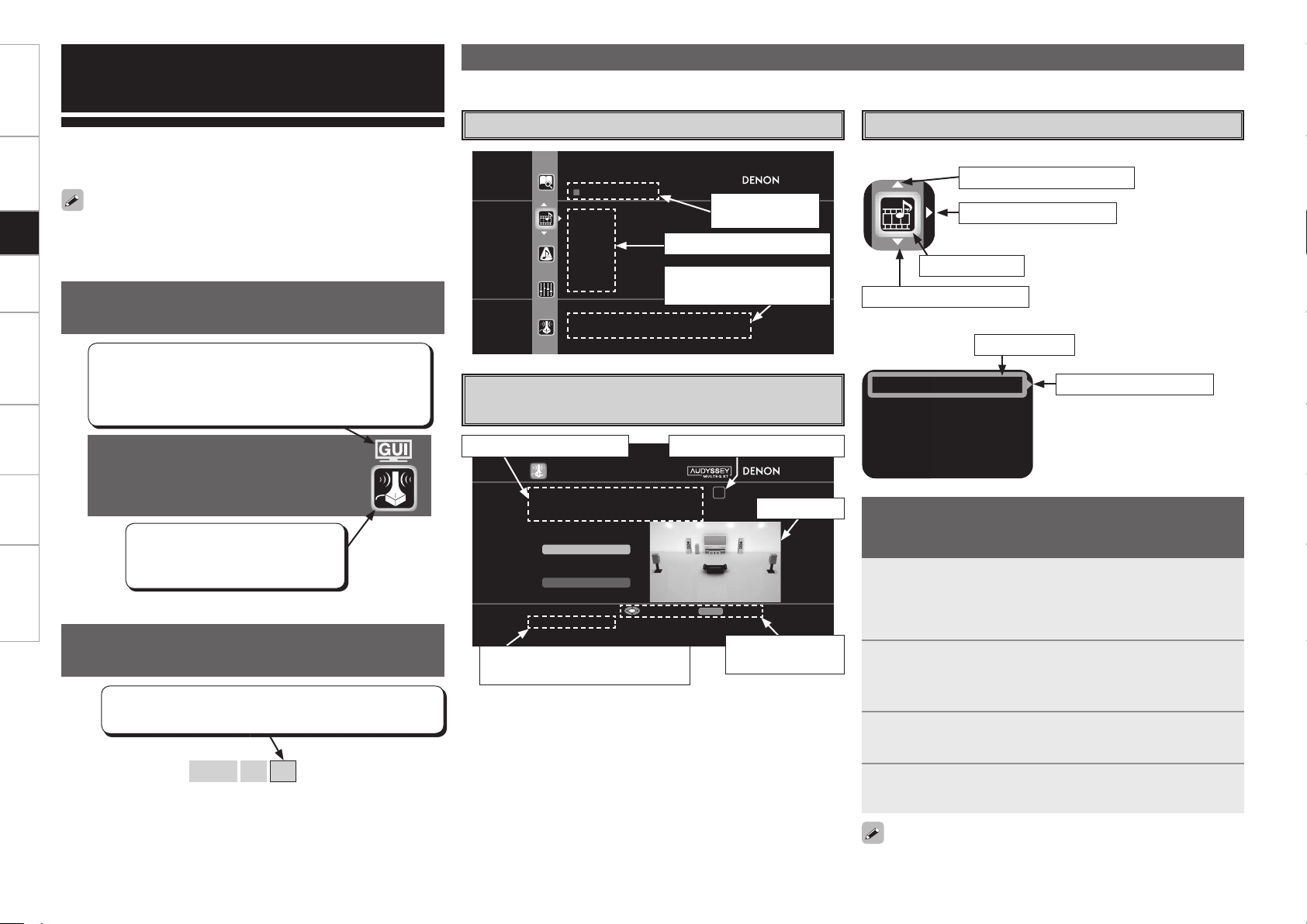
Auto Setup
Optimize settings for speakers in use.
Some typical examples are described below.
SOURCE SELECT
TUNER
PHONO
HDP
DVD
CD
TV/CBL
Select input source and make playback
settings
AUTO S ETUP
1 2 3 4 5
Start
RETURN
Amp As sign
STEP1 Speaker Det ection
Please place the microphone at ear
height at main li stening position.
Start Auto Setup
Enter Cancel
Config 5.1
Selected item
name
List of subsequent items
Guidance text for item at
cursor position
Illustration
Operation
button guidance
Guidance text for item at cursor
position
Operation guidance text
n Icon
n List
Assign
Input Mode
Rename
Other
Switch the selected item
Selected item
Switch the selected item
Switch to the next item
Selected item
Example of the Display of the GUI
Mark at a Title
Example: Browse Menu (Top Menu)
Examples of GUI Screen Displays
Example: Menus with Illustrations
(Auto Setup)
Cursor Position Display
Operations
The same operation is possible on the main unit
or remote control unit.
GUI Menu Operations
With the AVR-3808CI, settings and operations for most functions can
be performed by operating while looking at the GUI menus displayed
on the monitor screen.
b Switch the selected item using
ui.
1
Press the MENU button.
The GUI menu is displayed.
b To operate from the main remote control unit, be sure to set the
remote control unit to the AMP mode.
2
Press the u i p button to select the menu to be set
or operated.
b To return to the previous item, press the o or RETURN button.
3
Press the ENTER button to enter the setting.
4
Press the MENU button to fi nish.
Example of Display of Default
Values
[Selectable items] 7.1 (B)
7.1
5.1
In lists of selectable items or adjustable ranges, the item
surrounded by a border is the default value.
Items for which this mark is indicated at the title can be
operated from the GUI.
We recommend performing such operations from the
GUI.
This is the GUI icon for this setting
item or for the menu series to which
this item belongs.
Switch to the next item
The GUI cannot be superimposed when xvYCC signals and component
1080p signal, computer’s resolution (e.g.VGA) are input.
Getting Started Connections Setup Playback Remote Control Multi-Zone Information Troubleshooting
Operation step indicators
When “Screensaver” is set to “ON”, the screensaver is activated if no
operation is performed for about 3 minutes.
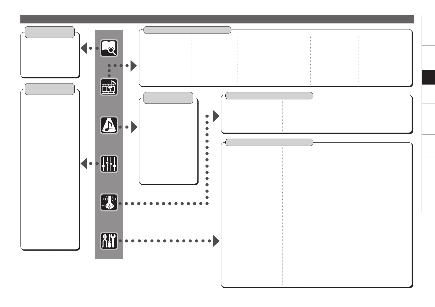
GUI Menu Map
Parameter
(vpage 41 ~ 44)
Information
(vpage 44, 45)
n Status
• MAIN ZONE
• ZONE2/3
n Audio Input Signal
n HDMI Information
n Auto Surround Mode
n Quick Select
n Preset Station
n Audio
• Surround Parameters
· Mode
· Cinema EQ
· DRC
· D.COMP
· LFE
· Center Image
· Panorama
· Dimension
· Center Width
· Delay Time
· Effect
· Effect Level
· Room Size
· AFDM
· SB CH Out
· Subwoofer Att.
· Subwoofer
· Default
• Tone
· Tone Defeat
· Bass
· Treble
• Room EQ
• RESTORER
• Night Mode
• Audio Delay
n Picture Adjust
• Contrast
• Brightness
• Chroma Level
• Hue
Manual Setup
(vpage 28 ~ 36)
n
Speaker Setup (vpage 28, 29)
• Speaker Confi guration
• Subwoofer Mode
• Distance
• Channel Level
• Crossover Frequency
• Surround Speaker
n HDMI Setup (vpage 30)
• i/p Scaler
• Resolution
• Progressive Mode
• Aspect
• Color Space
• RGB Range
• Auto Lip Sync
• Audio
n Audio Setup (vpage 30, 31)
• EXT. IN Setup
· Surround Speaker
· Subwoofer Level
• 2ch Direct/Stereo
• Downmix Option
• Auto Surround
• Manual EQ
Auto Setup
(vpage 25 ~ 27)
n Auto Setup
• STEP1: Speaker Detection
• STEP2: Measurement
• STEP3: Calculation
• STEP4: Check
• STEP5: Store
n Option
• Room EQ
• Direct Mode
• Mic Select
n Parameter
• Speaker Confi guration Check
• Distance Check
• Channel Level Check
• Crossover Check
• EQ Check
• Restore
n Network Setup
(vpage 31, 32)
• Network Setup
• Other
· Power Saving
· Character
· PC Language
• Network Information
n Zone Setup (vpage 33)
• ZONE2
· Bass
· Treble
· HPF
· Lch Level
· Rch Level
· Channel
· Volume Level
· Volume Limit
· Power On Level
· Mute Level
• ZONE3
· Bass
· Treble
· HPF
· Lch Level
· Rch Level
· Channel
· Volume Level
· Volume Limit
· Power On Level
· Mute Level
n
Option Setup (vpage 33 ~ 36)
• Amp Assign
• Volume Control
· Volume Limit
· Power On Level
· Mute Level
• Source Delete
• GUI
· Screensaver
· Wall Paper
· Format
· Text
· Master Volume
· NET/USB
· iPod
· Tuner
• Quick Select Name
• Trigger Out 1
• Trigger Out 2
• Remote ID
• 2Way Remote
• Dimmer
• Setup Lock
• Maintenance Mode
• Firmware Update
n Language (vpage 36)
Source Select
(vpage 36 ~ 40)
n TUNER (FM/AM)
• Play
• Auto Preset
• Preset Skip
• Preset Name
• Input Mode
• Rename
• Other
· Video Select
· Source Level
n PHONO
• Input Mode
• Rename
• Other
· Video Select
· Source Level
n CD, DVD, HDP, TV/CBL,
SAT, VCR, DVR, V.AUX
• Play (iPod)
• Playback Mode (iPod)
• Assign
• Input Mode
• Rename
• Other
· Video Select
·
Video Convert (Excluding CDs)
· Source Level
n NET/USB
• Play
• Playback Mode
• Input Mode
• Rename
• Other
· Video Select
· Source Level
n XM
• Play
• Preset Skip
• Antenna Aiming
• Input Mode
• Rename
• Other
· Video Select
· Source Level
Surround Mode
(vpage 40, 41)
n STEREO
n DIRECT
n STANDARD
n DOLBY PL
II
x, DOLBY PL
II
or
DOLBY PL
n DTS NEO:6
n neural
n 7CH STEREO
n WIDE SCREEN
n SUPER STADIUM
n ROCK ARENA
n JAZZ CLUB
n CLASSIC CONCERT
n MONO MOVIE
n VIDEO GAME
n MATRIX
n VIRTUAL
Getting Started Connections Setup Playback Remote Control Multi-Zone Information Troubleshooting
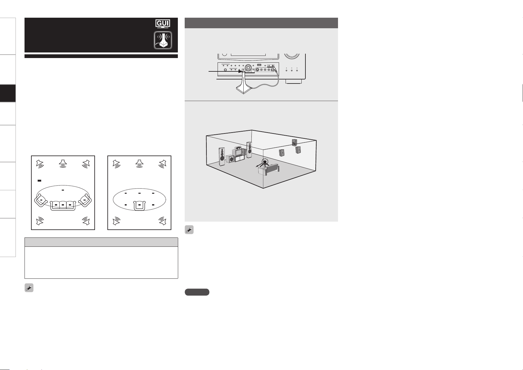
Getting Started Connections Setup Playback Remote Control Multi-Zone Information Troubleshooting
• Audyssey MultEQ
®
XT automatically measures the acoustical
problems in the listening environment to create the best audio
experience for your home theater.
• It optimizes a large listening area where one or more listeners are
seated.
Measurements are performed by placing the calibrated microphone
(DM-A405) successively at multiple positions throughout the
listening area as shown in Example q. For best results, it is
strongly recommended to measure 6 or more positions so that the
measurements have the proper spatial weighting.
Even if the listening environment is small as shown in Example w,
measuring at multiple points throughout the listening environment
results in more effective correction.
Preparations
When using a subwoofer, make the following settings before starting
the auto setup procedure:
• Defeat the volume and crossover controls if possible
• If this is not possible then set
•
Volume: “12 o’clock” position
•
Crossover frequency: “Maximum/Highest Frequency”
•
Low pass fi lter: “Off”
•
Standby mode: “Off”
NOTE
• Do not disconnect the setup microphone until the auto setup
procedure is completed.
• When using headphones, unplug the headphones before starting
the auto setup procedure.
Auto Setup
To make manual adjustments to the settings, see pages 28, 29.
1
Connect the included calibrated setup microphone to
the SETUP MIC jack on the main unit.
The auto setup screen appears automatically.
2
Place the microphone at ear height on a tripod or stand
with the microphone pointing directly up towards the
ceiling.
b It is not recommended to hold it in your hand. Be sure that the
path from microphone to the speakers is not blocked by objects.
Avoid placing the microphone close to a seat back or wall as sound
refl ections may give inaccurate results.
Sound
receptor
Setup
microphone
About the main listening position (*M)
The main listening position refers to the most central position where
one would normally sit within the listening environment.
MultEQ XT uses the measurements from this position to calculate
speaker distance, level, polarity, and the optimum crossover value
for the subwoofer.
*
M
*
M
Example q Example w
( :Measuring positions)
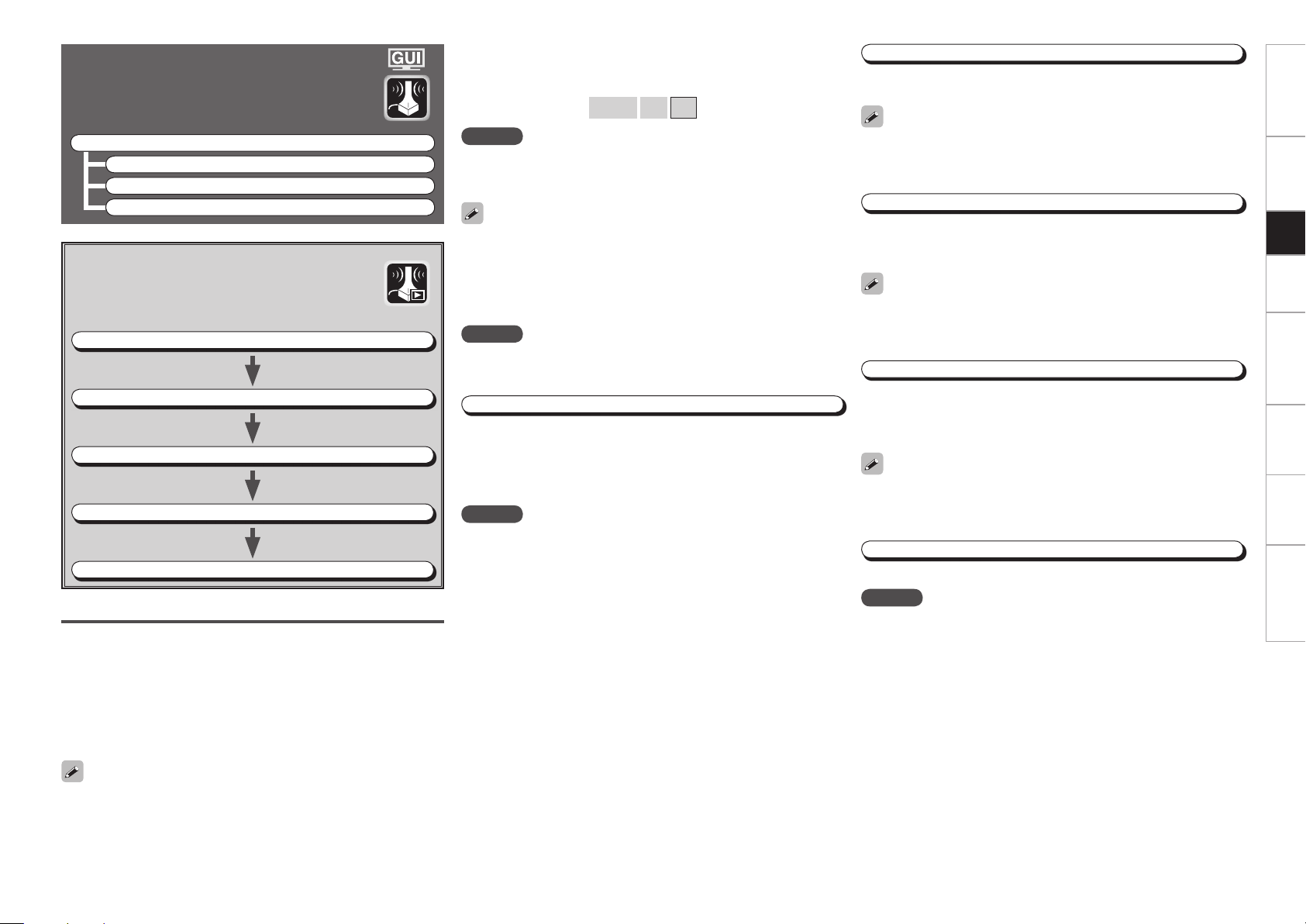
Getting Started Connections Setup Playback Remote Control Multi-Zone Information Troubleshooting
Auto Setup
Optimize settings for speakers in use.
F Menu tree F
Auto Setup
a Auto Setup
s Option
d Parameter
Start
Start Auto Setup.
The Audyssey MultEQ XT Auto Setup process automatically calculates
the size, level, distance, bass management crossover frequency, and
optimal settings for each speaker and subwoofer. Audyssey MultEQ
XT corrects acoustical distortions within the listening area.
Before starting, connect and position all your speakers.
Once started, MultEQ XT will play a series of test tones through each
speaker.
[Selectable items] 7.1 (B)
7.1
5.1
a Auto Setup
The settings are performed automatically.
GAuto setup fl owG
STEP1: Speaker Detection
STEP2: Measurement (2 to 8 positions)
STEP3: Calculation
STEP4: Check
STEP5: Store
NOTE
Do not turn the power off while the settings are being stored.
STEP2: Measurement
After completing a measurement position, move the microphone to
the next position.
Measure at least 6 positions (main listening position and at least 5 other
surrounding positions). For best results it is recommend measuring 6
or more positions (with a maximum of 8 positions).
STEP3: Calculation
When “Calculate” is selected at “STEP2”, the measurements taken
are analyzed automatically to determine how the speaker system
interacts with the room.
The time required for this analysis depends on the number of speakers
connected. The higher the number of speakers, the longer the time
required for analysis.
STEP4: Check
Once the auto setup procedure is complete, a measuring result check
screen appears.
Select any item whose results you want to check to review the
results.
Values that are different from the actual distance may be set for
speakers with built-in fi lters (subwoofers, etc.). This is because fi lters
add electrical delay to the signal that should be compensated.
STEP5: Store
The auto setup measurement results are stored in the AVR-3808CI.
Confi guration
The speaker system to be measured can be selected ahead of time
here.
If an error message appears during the measurements, check “Error
Messages” (vpage 27), take the advised action, then start the
measurements again.
Setting the correct speaker confi guration can reduce the time required
to measure during the auto setup procedure as the system will not
have to look for speakers that are not connected.
The speaker connection and polarity are detected at the fi rst
measurement position. The following attributes are also determined
at this time: “Speaker Size”, “Speaker Distance”, “Channel Level”,
“Crossover Frequency”.
Once the measurements are completed, the results are displayed.
STEP1 : Speaker Detection
NOTE
• Loud test tone may be played during Audyssey MultEQ XT Automatic
Speaker Setup. This is part of normal operation. If there is background
noise in room, these test tones will increase in volume.
• Do not stand between the speakers and setup microphone or allow
obstacles in the path while the measurements are being made. This
will cause inaccurate readings.
• Quiet the listening environment before beginning measurements and
refrain from talking. Turn off air conditioning units or other devices
that emit noise if at all possible as measurements may be affected
by these sounds.
• Operating the MASTER VOLUME knob on the main unit or the VOL
+/– buttons on the remote control unit during the measurements will
cancel the measurements.
• Do not change the speaker connections or subwoofer volume after
“STEP1”.
Amp Assign
Advanced setting : changes power amplifi er assignment.
NOTE
The items selectable at “Confi g.” differ according to the “Amp Assign”
settings.
NOTE
“Amp Assign” is initially set to “ZONE2”, so “7.1 (B)” and “7.1” cannot
be selected. To use “7.1 (B)” or “7.1”, change the “Amp Assign” setting
(vpage 68 ~ 70).
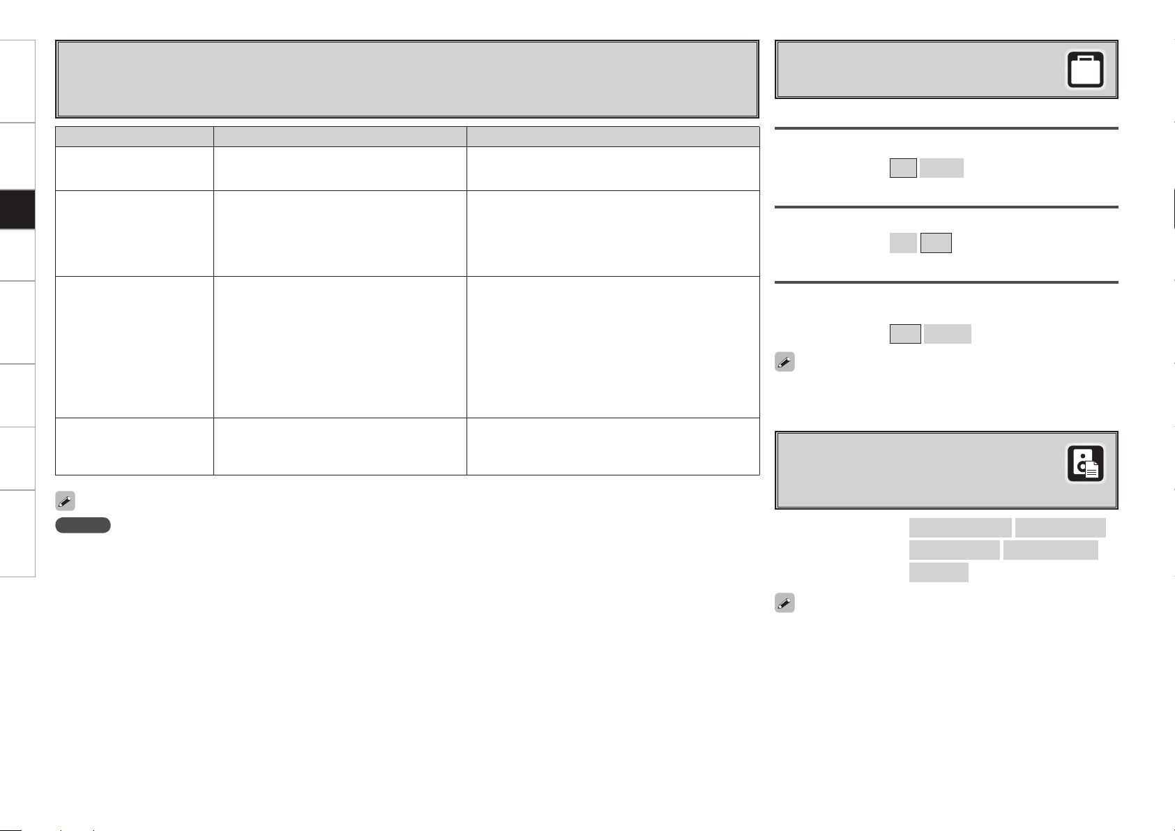
Error Messages
If the auto setup procedure could not be completed due to speaker installation, the measuring environment, etc., an error
message is displayed. If this happens, check the relevant items, be sure to take the necessary measures, then perform
the auto setup procedure over again.
Error messages (examples) Cause Measures
No microphone or speaker • Included setup microphone is not connected.
• Not all speakers could be detected.
• Connect the included setup microphone to the SETUP MIC
jack on the main unit.
• Check the speaker connections.
Ambient noise is too high
or Level is too low
• Too much noise in the room for accurate
measurements to be made.
• Speaker or subwoofer sound is too low for
accurate measurements to be made.
• Either turn off any device generating noise or move it
away.
• Try again when the surroundings are quieter.
• Check the speaker installation and the direction in which
the speakers are facing.
• Adjust the subwoofer’s volume.
None • Displayed speaker could not be detected.
· The front L and front R speakers were not
properly detected.
· Only one channel of the surround (A) and
surround (B) speakers was detected.
· Sound was output from the R channel when only
one surround back speaker was connected.
· The surround back or the surround (B) speaker
was detected, but the surround (A) speaker
was not detected.
• Check the connections of the displayed speaker.
Phase • Displayed speaker connected with the polarities
reversed.
• Check the polarities of the displayed speaker.
• For some speakers, this error message may be displayed
even if the speaker is properly connected. If you are sure
that the wiring is correct, select “Skip”.
NOTE
Be sure to turn the power off before checking the speaker connections.
Room EQ
Select room EQ setting method.
s
Option
Select settings for room EQ, mic, etc.
[Selectable items] All
Assign
Direct Mode
Select room EQ use for DIRECT or PURE DIRECT mode.
[Selectable items] ON
OFF
Mic Select
Select the microphone type if not using supplied mic.
The microphone connected to V.AUX Lch is used.
[Selectable items] Mic
V.AUX L
d
Parameter Check
Check auto setup measurement results.
This is displayed after the auto setup procedure
is completed.
Spkr Confi g Check
Distance Check
Ch. Level Check
Crossover Check
EQ Check
[Items to be checked]
Select “Retry” to make the measurements again.
Getting Started Connections Setup Playback Remote Control Multi-Zone Information Troubleshooting
The auto setup results can be reset to what was originally calculated
by MultEQ XT when “Restore” is selected.
Only a professionally certifi ed installer should ever connect a
professionally-calibrated microphone to the V.AUX L input on the front
panel.
 Loading...