


TP305
10" Contractors Saw
(Model 36-978/36-979)
12½" Portable
Planer
Raboteuse portative de
317 mm (12½ po)
Acepilladora Portátil
12½" pulgadas
Instruction Manual Manuel d’Utilisation Manual de Instrucciones
FRANÇAISE (17) ESPAÑOL (33)
WWW.DELTAMACHINERY.COM
(800) 223-7278 - US
(800) 463-3582 - CANADA
A15104 - 01-13-06 Copyright ©
2006 Delta Machinery

TABLE OF CONTENTS
IMPORTANT SAFETY INSTRUCTIONS . . . . . . . . . . . . . . . . . . . . . . . . . . . . . . . . . . . . . . . . . . . . . . . . . . . . . . . . . . . 2 SAFETY GUIDELINES - DEFINITIONS . . . . . . . . . . . . . . . . . . . . . . . . . . . . . . . . . . . . . . . . . . . . . . . . . . . . . . . . . . . 3 ADDITIONAL SPECIFIC SAFETY RULES . . . . . . . . . . . . . . . . . . . . . . . . . . . . . . . . . . . . . . . . . . . . . . . . . . . . . . . . . 5 FUNCTIONAL DESCRIPTION . . . . . . . . . . . . . . . . . . . . . . . . . . . . . . . . . . . . . . . . . . . . . . . . . . . . . . . . . . . . . . . . . . 7 CARTON CONTENTS . . . . . . . . . . . . . . . . . . . . . . . . . . . . . . . . . . . . . . . . . . . . . . . . . . . . . . . . . . . . . . . . . . . . . . . . . 7 ASSEMBLY . . . . . . . . . . . . . . . . . . . . . . . . . . . . . . . . . . . . . . . . . . . . . . . . . . . . . . . . . . . . . . . . . . . . . . . . . . . . . . . . . 8 OPERATION . . . . . . . . . . . . . . . . . . . . . . . . . . . . . . . . . . . . . . . . . . . . . . . . . . . . . . . . . . . . . . . . . . . . . . . . . . . . . . . . 9 TROUBLESHOOTING . . . . . . . . . . . . . . . . . . . . . . . . . . . . . . . . . . . . . . . . . . . . . . . . . . . . . . . . . . . . . . . . . . . . . . . . 14 MAINTENANCE. . . . . . . . . . . . . . . . . . . . . . . . . . . . . . . . . . . . . . . . . . . . . . . . . . . . . . . . . . . . . . . . . . . . . . . . . . . . . 14 SERVICE . . . . . . . . . . . . . . . . . . . . . . . . . . . . . . . . . . . . . . . . . . . . . . . . . . . . . . . . . . . . . . . . . . . . . . . . . . . . . . . . . . 16 ACCESSORIES . . . . . . . . . . . . . . . . . . . . . . . . . . . . . . . . . . . . . . . . . . . . . . . . . . . . . . . . . . . . . . . . . . . . . . . . . . . . . 16 WARRANTY. . . . . . . . . . . . . . . . . . . . . . . . . . . . . . . . . . . . . . . . . . . . . . . . . . . . . . . . . . . . . . . . . . . . . . . . . . . . . . . . 16 FRANÇAIS . . . . . . . . . . . . . . . . . . . . . . . . . . . . . . . . . . . . . . . . . . . . . . . . . . . . . . . . . . . . . . . . . . . . . . . . . . . . . . . . . 17 ESPAÑOL. . . . . . . . . . . . . . . . . . . . . . . . . . . . . . . . . . . . . . . . . . . . . . . . . . . . . . . . . . . . . . . . . . . . . . . . . . . . . . . . . . 33
IMPORTANT SAFETY INSTRUCTIONS
 Read and understand all warnings and operating instructions before using any tool
or equipment. When using tools or equipment, basic safety precautions should always be followed to reduce the risk of personal injury. Improper operation, maintenance or modification of tools or equipment could result in serious injury and property damage. There are certain applications for which
tools and equipment are designed. Delta Machinery strongly recommends that this product NOT be modified and/or used for any application other than for which it was designed.
If you have any questions relative to its application DO NOT use the product until you have written Delta Machinery and we have advised you.
Online contact form at www.deltamachinery.com
Postal Mail: Technical Service Manager
Delta Machinery
4825 Highway 45 North
Jackson, TN 38305
(IN CANADA: 125 Mural St. Suite 300, Richmond Hill, ON, L4B 1M4)
Information regarding the safe and proper operation of this tool is available from the following sources: Power Tool Institute
1300 Sumner Avenue, Cleveland, OH 44115-2851 www.powertoolinstitute.org
National Safety Council
1121 Spring Lake Drive, Itasca, IL 60143-3201
American National Standards Institute, 25 West 43rd Street, 4 floor, New York, NY 10036 www.ansi.org
ANSI 01.1Safety Requirements for Woodworking Machines, and the U.S. Department of Labor regulations www.osha.gov
SAVE THESE INSTRUCTIONS!
2

SAFETY GUIDELINES - DEFINITIONS
It is important for you to read and understand this manual. The information it contains relates to protecting YOUR SAFETY and PREVENTING PROBLEMS. The symbols below are used to help you recognize this information.
Indicates an imminently hazardous situation which, if not avoided, will result in death or serious injury.
Indicates a potentially hazardous situation which, if not avoided, could result in death or serious injury.
Indicates a potentially hazardous situation which, if not avoided, may result in minor or moderate injury.
Used without the safety alert symbol indicates potentially hazardous situation which, if not avoided, may result in property damage.
CALIFORNIA PROPOSITION 65
 Some dust created by power sanding, sawing, grinding, drilling, and other construction activities contains chemicals known to cause cancer, birth defects or other reproductive harm. Some examples of these chemicals are:
•lead from lead-based paints,
•crystalline silica from bricks and cement and other masonry products, and
•arsenic and chromium from chemically-treated lumber.
Your risk from these exposures varies, depending on how often you do this type of work. To reduce your exposure to these chemicals: work in a well ventilated area, and work with approved safety equipment, always wear NIOSH/OSHA approved, properly fitting face mask or respirator when using such tools.
3

GENERAL SAFETY RULES
 Failure to follow these rules may result in serious personal injury.
1.FOR YOUR OWN SAFETY, READ THE INSTRUCTION MANUAL BEFORE OPERATING THE MACHINE.
Learning the machine’s application, limitations, and specific hazards will greatly minimize the possibility of accidents and injury.
2.WEAR EYE AND HEARING PROTECTION. ALWAYS USE SAFETY GLASSES. Everyday eyeglasses are NOT safety glasses. USE CERTIFIED SAFETY EQUIPMENT. Eye protection equipment should comply with ANSI Z87.1 standards. Hearing equipment should comply with ANSI S3.19 standards.
3.WEAR PROPER APPAREL. Do not wear loose clothing, gloves, neckties, rings, bracelets, or other jewelry which may get caught in moving parts. Nonslip protective footwear is recommended. Wear protective hair covering to contain long hair.
4.DO NOT USE THE MACHINE IN A DANGEROUS ENVIRONMENT. The use of power tools in damp or wet locations or in rain can cause shock or electrocution. Keep your work area well-lit to prevent tripping or placing arms, hands, and fingers in danger.
5.MAINTAIN ALL TOOLS AND MACHINES IN PEAK CONDITION. Keep tools sharp and clean for best and safest performance. Follow instructions for lubricating and changing accessories. Poorly maintained tools and machines can further damage the tool or machine and/or cause injury.
6.CHECK FOR DAMAGED PARTS. Before using the machine, check for any damaged parts. Check for alignment of moving parts, binding of moving parts, breakage of parts, and any other conditions that may affect its operation. A guard or any other part that is damaged should be properly repaired or replaced with Delta or factory authorized replacement parts.
Damaged parts can cause further damage to the machine and/or injury.
7.KEEP THE WORK AREA CLEAN. Cluttered areas and benches invite accidents.
8.KEEP CHILDREN AND VISITORS AWAY. Your shop is a potentially dangerous environment. Children and visitors can be injured.
9.REDUCE THE RISK OF UNINTENTIONAL STARTING.
Make sure that the switch is in the "OFF" position before plugging in the power cord. In the event of a power failure, move the switch to the "OFF" position. An accidental start-up can cause injury. Do not touch the plug’s metal prongs when unplugging or plugging in the cord.
10.USE THE GUARDS. Check to see that all guards are in place, secured, and working correctly to prevent injury.
11.REMOVE ADJUSTING KEYS AND WRENCHES BEFORE STARTING THE MACHINE. Tools, scrap pieces, and other debris can be thrown at high speed, causing injury.
12.USE THE RIGHT MACHINE. Don’t force a machine or an attachment to do a job for which it was not designed. Damage to the machine and/or injury may result.
13.USE RECOMMENDED ACCESSORIES. The use of accessories and attachments not recommended by Delta may cause damage to the machine or injury to the user.
14.USE THE PROPER EXTENSION CORD. Make sure your extension cord is in good condition. When using an extension cord, be sure to use one heavy enough to carry the current your product will draw. An undersized cord will cause a drop in line voltage, resulting in loss of power and overheating. See the Extension Cord Chart for the correct size depending on the cord length and nameplate ampere rating. If in doubt, use the next heavier gauge. The smaller the gauge number, the heavier the cord.
15.SECURE THE WORKPIECE. Use clamps or a vise to hold the workpiece when practical. Loss of control of a workpiece can cause injury.
16.FEED THE WORKPIECE AGAINST THE DIRECTION OF THE ROTATION OF THE BLADE, CUTTER, OR ABRASIVE SURFACE. Feeding it from the other direction will cause the workpiece to be thrown out at high speed.
17.DON’T FORCE THE WORKPIECE ON THE MACHINE.
Damage to the machine and/or injury may result.
18.DON’T OVERREACH. Loss of balance can make you fall into a working machine, causing injury.
19.NEVER STAND ON THE MACHINE. Injury could occur if the tool tips, or if you accidentally contact the cutting tool.
20.NEVER LEAVE THE MACHINE RUNNING UNATTENDED. TURN THE POWER OFF. Don’t leave the machine until it comes to a complete stop. A child or visitor could be injured.
21.TURN THE MACHINE "OFF", AND DISCONNECT THE MACHINE FROM THE POWER SOURCE before installing or removing accessories, changing cutters, adjusting or changing set-ups. When making repairs, be sure to lock the start switch in the "OFF" position. An accidental start-up can cause injury.
22.MAKE YOUR WORKSHOP CHILDPROOF WITH PADLOCKS, MASTER SWITCHES, OR BY REMOVING STARTER KEYS. The accidental start-up of a machine by a child or visitor could cause injury.
23. STAY ALERT, WATCH WHAT YOU ARE DOING,
AND USE COMMON SENSE. DO NOT USE THE MACHINE WHEN YOU ARE TIRED OR UNDER THE INFLUENCE OF DRUGS, ALCOHOL, OR MEDICATION. A moment of inattention while operating power tools may result in injury.
24.  U S E O F T H I S T O O L C A N
GENERATE AND DISBURSE DUST OR OTHER AIRBORNE PARTICLES, INCLUDING WOOD DUST, CRYSTALLINE SILICA DUST AND ASBESTOS DUST.
Direct particles away from face and body. Always operate tool in well ventilated area and provide for proper dust removal. Use dust collection system wherever possible. Exposure to the dust may cause serious and permanent respiratory or other injury, including silicosis (a serious lung disease), cancer, and death. Avoid breathing the dust, and avoid prolonged contact with dust. Allowing dust to get into your mouth or eyes, or lay on your skin may promote absorption of harmful material. Always use properly fitting NIOSH/ OSHA approved respiratory protection appropriate for the dust exposure, and wash exposed areas with soap and water.
4

ADDITIONAL SPECIFIC SAFETY RULES
 Failure to follow these rules may result in serious personal injury.
1.DO NOT OPERATE THIS MACHINE until it is completely assembled and installed according to the instructions. A machine incorrectly assembled can cause serious injury.
2.OBTAIN ADVICE from your supervisor, instructor, or another qualified person if you are not thoroughly familiar with the operation of this machine. Knowledge is safety.
3.FOLLOW ALL WIRING CODES and recommended electrical connections to prevent shock or electrocution.
4.KEEP KNIVES SHARP and free from rust and pitch. Dull or rusted knives work harder and can cause kickback.
5.NEVER TURN THE MACHINE "ON" before clearing the table of all objects (tools, scraps of wood, etc.). Flying debris can cause serious injury.
6. NEVER TURN THE MACHINE "ON" with the workpiece contacting the cutterhead. Kickback can occur.
7.SECURE THE MACHINE TO A SUPPORTING SURFACE to prevent the machine from sliding, walking or tipping over.
8.PROPERLY SECURE THE KNIVES IN THE CUTTERHEAD before turning the power "ON". Loose blades may be thrown out at high speeds causing serious injury.
9.LOCK THE SPEED SETTING SECURELY before feeding the workpiece through the machine. Changing speeds while planing can cause kickback.
10.AVOID AWKWARD OPERATIONS AND HAND POSITIONS. A sudden slip could cause a hand to move into the knives.
11.KEEP ARMS, HANDS, AND FINGERS away from the cutterhead, the chip exhaust opening, and the feed rollers to prevent severe cuts.
12.NEVER REACH INTO THE CUTTERHEAD AREA while the machine is running. Your hands can be drawn into the knives.
13.DO NOT STAND IN LINE OF THE WORKPIECE.
Kickback can cause injury.
14.ALLOW THE CUTTERHEAD TO REACH FULL SPEED before feeding a workpiece. Changing speeds while planing can cause kickback.
15.WHEN PLANING BOWED STOCK, place the concave (cup down) side of the stock on the table and cut with the grain to prevent kickback.
16.DO NOT FEED A WORKPIECE that is warped, contains knots, or is embedded with foreign objects (nails, staples, etc.). Kickback can occur.
17.DO NOT FEED A SHORT, THIN, OR NARROW WORKPIECE INTO THE MACHINE. Your hands can be drawn into the knives and/or the workpiece can be thrown at high speeds. See the "OPERATION" section of this instruction manual for details.
18.DO NOT FEED A WORKPIECE into the outfeed end of the machine. The workpiece will be thrown out of the opposite side at high speeds.
19.REMOVE SHAVINGS ONLY with the power "OFF" to prevent serious injury.
20.PROPERLY SUPPORT LONG OR WIDE WORKPIECES. Loss of control of the workpiece can cause serious injury.
21.NEVER PERFORM LAYOUT, ASSEMBLY or set-up work on the table/work area when the machine is running. Serious injury will result.
22.TURN THE MACHINE "OFF", DISCONNECT IT FROM THE POWER SOURCE, and clean the table/work area before leaving the machine. LOCK THE SWITCH IN THE "OFF" POSITION to prevent un-authorized use. Someone else might accidentally start the machine and cause injury to themselves or others.
23.ADDITIONAL INFORMATION regarding the safe and proper operation of power tools (i.e. a safety video) is available from the Power Tool Institute, 1300 Sumner Avenue, Cleveland, OH 44115-2851 (www. powertoolinstitute.com). Information is also available from the National Safety Council, 1121 Spring Lake Drive, Itasca, IL 60143-3201. Please refer to the American National Standards Institute ANSI 01.1 Safety Requirements for Woodworking Machines and the U.S. Department of Labor Regulations.
SAVE THESE INSTRUCTIONS.
Refer to them often and use them to instruct others.
5
POWER CONNECTIONS
A separate electrical circuit should be used for your machines. This circuit should not be less than #12 wire and should be protected with a 20 Amp time lag fuse. If an extension cord is used, use only 3-wire extension cords which have 3-prong grounding type plugs and matching receptacle which will accept the machine’s plug. Before connecting the machine to the power line, make sure the switch (s) is in the "OFF" position and be sure that the electric current is of the same characteristics as indicated on the machine. All line connections should make good contact. Running on low voltage will damage the machine.
 Do not expose the machine to rain or operate the machine in damp locations.
MOTOR SPECIFICATIONS
Your machine is wired for 120V, 60 HZ alternating current. Before connecting the machine to the power source, make sure the switch is in the "OFF" position.
GROUNDING INSTRUCTIONS
 This machine must be grounded while in use to protect the operator from electric shock.
1.All grounded, cord-connected machines:
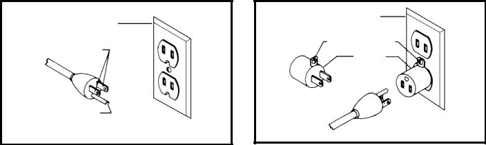
In the event of a malfunction or breakdown, grounding provides a path of least resistance for electric current to reduce the risk of electric shock. This machine is equipped with an electric cord having an equipment-grounding conductor and a grounding plug. The plug must be plugged into a matching outlet that is properly installed and grounded in accordance with all local codes and ordinances.
Do not modify the plug provided - if it will not fit the outlet, have the proper outlet installed by a qualified electrician.
Improper connection of the equipment-grounding conduc-tor can result in risk of electric shock. The conductor with insulation having an outer surface that is green with or without yellow stripes is the equipment-grounding conductor. If repair or replacement of the electric cord or plug is necessary, do not connect the equipment-grounding conductor to a live terminal.
Check with a qualified electrician or service personnel if the grounding instructions are not completely understood, or if in doubt as to whether the machine is properly grounded.
Use only 3-wire extension cords that have 3-prong grounding type plugs and matching 3-conductor receptacles that accept the machine’s plug, as shown in Fig. A.
Repair or replace damaged or worn cord immediately.
2.Grounded, cord-connected machines intended for use on a supply circuit having a nominal rating less than 150 volts:
If the machine is intended for use on a circuit that has an outlet that looks like the one illustrated in Fig. A, the machine will have a grounding plug that looks like the plug illustrated in Fig. A. A temporary adapter, which looks like the adapter illustrated in Fig. B, may be used to connect this plug to a matching 2-conductor receptacle as shown in Fig. B if a properly grounded outlet is not available. The temporary adapter should be used only until a properly grounded outlet can be installed by a qualified electrician. The green-colored rigid ear, lug, and the like, extending from the adapter must be connected to a permanent ground such as a properly grounded outlet box. Whenever the adapter is used, it must be held in place with a metal screw.
NOTE: In Canada, the use of a temporary adapter is not permitted by the Canadian Electric Code.
 In all cases, make certain that the receptacle in question is properly grounded. If you are not sure, have a qualified electrician check the receptacle.
|
GROUNDED OUTLET BOX |
||
GROUNDED OUTLET BOX |
|
|
|
CURRENT |
GROUNDING MEANS |
||
|
|
|
|
CARRYING |
|
|
|
|
ADAPTER |
|
|
PRONGS |
|
|
|
|
|
|
|
|
|
|
|
GROUNDING BLADE
IS LONGEST OF THE 3 BLADES
Fig. A |
Fig. B |
6

EXTENSION CORDS
 Use proper extension cords. Make sure your extension cord is in good condition and is a 3-wire extension cord which has a 3-prong grounding type plug and matching receptacle which will accept the machine’s plug. When using an extension cord, be sure to use one heavy enough to carry the current of the machine. An undersized cord will cause a drop in line voltage, resulting in loss of power and overheating. Fig. C, shows the correct gauge to use depending on the cord length. If in doubt, use the next heavier gauge. The smaller the gauge number, the heavier the cord.
MINIMUM GAUGE EXTENSION CORD
RECOMMENDED SIZES FOR USE WITH STATIONARY ELECTRIC MACHINES
|
|
Total |
|
|
Ampere |
|
Length of |
|
|
|
Cord in |
|
Gauge of Extension |
|
|
|
|
||
Rating |
Volts |
Feet |
|
Cord |
0-6 |
120 |
up to 25 |
|
18 AWG |
0-6 |
120 |
25-50 |
|
16 AWG |
0-6 |
120 |
50-100 |
|
16 AWG |
0-6 |
120 |
100-150 |
|
14 AWG |
6-10 |
120 |
up to 25 |
|
18 AWG |
6-10 |
120 |
25-50 |
|
16 AWG |
6-10 |
120 |
50-100 |
|
14 AWG |
6-10 |
120 |
100-150 |
|
12 AWG |
10-12 |
120 |
up to 25 |
|
16 AWG |
10-12 |
120 |
25-50 |
|
16 AWG |
10-12 |
120 |
50-100 |
|
14 AWG |
10-12 |
120 |
100-150 |
|
12 AWG |
12-16 |
120 |
up to 25 |
|
14 AWG |
12-16 |
120 |
25-50 |
|
12 AWG |
12-16 |
120 |
GREATER THAN 50 FEET NOT RECOMMENDED |
||
|
|
Fig. C |
|
|
FUNCTIONAL DESCRIPTION
FOREWORD
Delta TP305 is a 12½" (317mm) Portable Planer. This planer can handle workpieces up to 12½" (317mm) wide and 6" (152mm) thick. The maximum depth of cut is 3/32" (2.4 mm). The TP305 features a powerful 15 amp, 120 volt motor, a two-knife cutterhead with double-edged reversible knives, knife-installation tool and wrench
NOTICE: The photo on the manual cover illustrates the current production model. All other illustrations contained in the manual are representative only and may not depict the actual labeling or accessories included. These are intended to illustrate technique only.
CARTON CONTENTS
3
4
6
|
|
|
|
1 |
|
|
|
|
|
|
|
|
|
|
|
|
|
|
|
|
|
|
|
|
|
|
|
|
|
|
|
|
|
|
|
|
|
|
|
|
|
|
|
|
|
|
5 |
|
|
|
|
|
|
|
|
|
|
|
|
|
|
|
|
|
|
|
|
|
|
|
|
|
|
|
|
|
|
|
|
|
|
|
|
|
|
|
|
|
2 |
|
|
|
|
|
|
|
|
|
|
||
|
|
|
|
|
|
|
|
|
|
|
|
|
|
|
|
|
|
|
|
|
|
|
|
|
|
|
|
|
|
|
|
|
|
|
|
|
|
|
|
|
|
|
|
|
|
|
|
|
7 |
|
|
|
Fig. 2 |
|
|
|
|
|
|
|
|
Fig. 3 |
|
||||
|
|
|
|
|
|
|
|
|
|
|
|
|
|
|
|
|
|
|
|
|
|
|
|
|
|
|
|
|
|
|
|
|
|
1. |
Planer |
3. |
Knife Transfer Tool |
|||||||||||||
2. |
Cutterhead Guard |
4. |
5mm Wrench Assembly |
|||||||||||||
|
|
|
|
5. |
M5 x 20mm Hex Socket Head Screw |
|||||||||||
|
|
|
|
6. |
M5x10mm Knob (2) |
|||||||||||
|
|
|
|
7. |
Elevating Handle |
|||||||||||
7
UNPACKING AND CLEANING
Carefully unpack the machine and all loose items from the shipping container(s). Remove the rust-preventative oil from unpainted surfaces using a soft cloth moistened with mineral spirits, paint thinner or denatured alcohol.


 Do not use highly volatile solvents such as gasoline, naphtha, acetone or lacquer thinner for cleaning your machine.
After cleaning, cover the unpainted surfaces with a good quality household floor paste wax.
ASSEMBLY
 For your own safety, do not connect the machine to the power source until the machine is completely assembled and you read and understand the entire instruction manual.
ASSEMBLY TOOLS REQUIRED
5mm wrench (included)
ASSEMBLY TIME ESTIMATE
Assembly for this machine takes approximately 30 minutes.
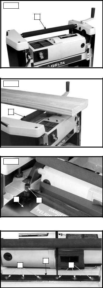
RAISING AND LOWERING HANDLE
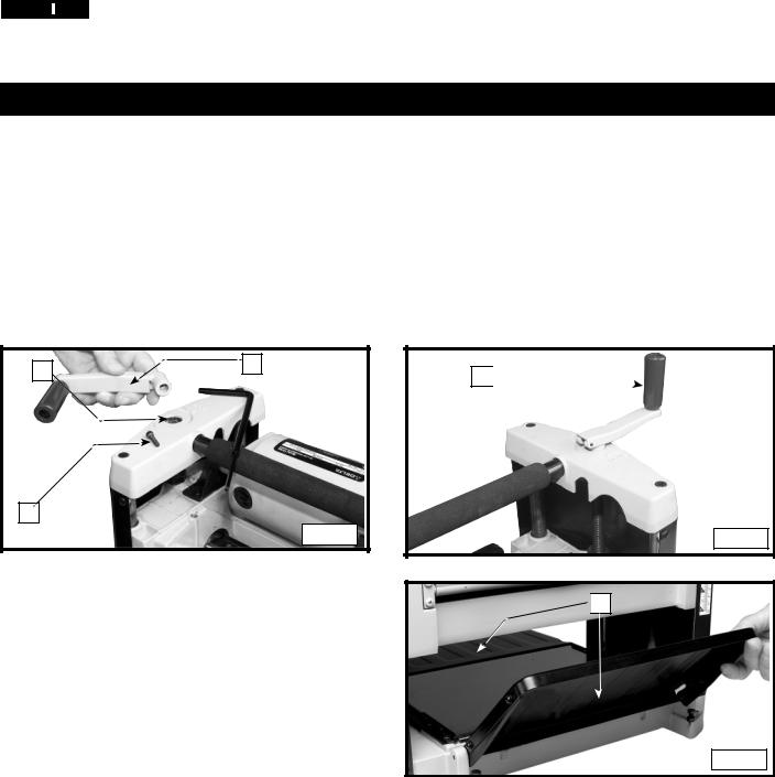
Attach the raising and lowering handle (A) Fig. 4 to the shaft (B) and fasten in place with M5x20mm screw (C). NOTE: Ensure that the flats of the handle and the flats on the shaft are aligned. Flip handle (A) upward as shown in Fig. 5.
B |
A |
|
C
Fig. 4
LOWERING EXTENSION TABLES
The infeed and outfeed extension tables (A) Fig. 6 are shipped attached to the machine in the raised position. Lower the tables (A) on both sides of the planer (Fig. 6). The top surface of extension tables should be level with the planer table. To check and adjust, refer to the section "LEVELING EXTENSION TABLES" in this manual.
A 


Fig. 5

 A
A
Fig. 6
8
CUTTERHEAD GUARD
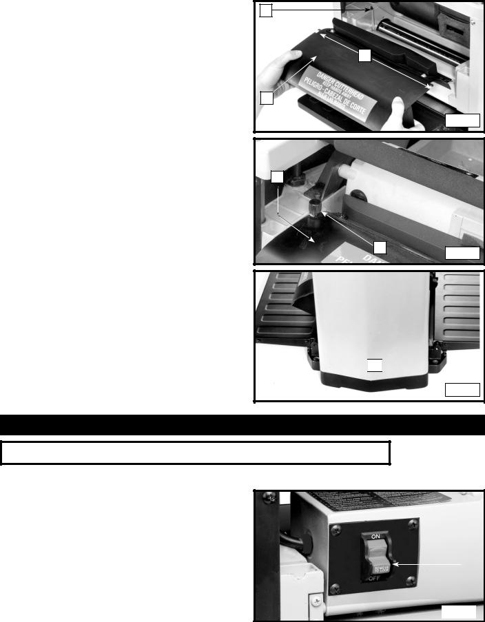
1.Attach the cutterhead guard (A) Fig. 7 to the planer by inserting the end of the guard over the top of the cutterhead. Place the slots in the cutterhead guard (C) over the tapped holes (B).
2.Fasten cutterhead guard (A) Fig. 8 to planer using two knobs, one of which is shown at (D).
 Make sure that the cutterhead guard is properly secured with the knobs before operating this machine.
B |
C |
A |
Fig. 7 |
FASTENING PLANER TO SUPPORTING SURFACE
During operation, if there is any tendency for the planer to tip over, slide or "walk" across the supporting surface, the planer must be secured to the supporting surface. Four holes (two of which are shown at (A) Fig. 9 are provided for this purpose.
A
D
Fig. 8

 A
A 

Fig. 9
OPERATION
OPERATIONAL CONTROLS AND ADJUSTMENTS
STARTING AND STOPPING PLANER
 Make sure that the switch is in the "OFF" position before plugging cord into outlet. Do not touch the plug’s metal prongs when unplugging or
plugging in the cord.
1. |
The on/off switch (A) Fig. 10 is located on the front |
|
|
|
|
|
of the planer moter. To turn the machine "ON", move |
|
|
|
|
|
the switch up to the "ON" position. |
|
|
|
|
2. |
To turn the machine "OFF", move the switch (A) down |
|
|
A |
|
|
|
|
|
||
|
to the "OFF" position. |
|
|
|
|
|
|
|
|
|
|
|
|
|
Fig. 10 |
||
|
|
|
|
|
|
9
LOCKING SWITCH IN THE "OFF" POSITION
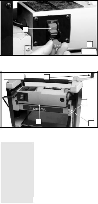
IMPORTANT: When the machine is not in use, the switch should be locked in the "OFF" position to prevent unauthorized use. To lock the machine, grasp the switch toggle (D) and pull it out of the switch (Fig. 11). With the switch toggle (D) removed, the switch will not operate. However, should the switch toggle be removed while the planer is running, the machine can be turned "OFF," but cannot be restarted without reinserting the switch toggle (D).
 In the event of a power outage (such as a breaker or fuse trip), always move the switch to the "OFF" position until the main power is restored.
A

 D
D
Fig. 11
RAISING AND LOWERING HEAD ASSEMBLY
The head assembly (A) Fig. 12A contains the cutterhead feed rollers, cutterhead guard and motor. Raising and lowering the head assembly controls the depth-of-cut on your planer. To raise or lower the head assembly, rotate the handle (D).
NOTE: One revolution of the handle will move the cutterhead up or down approximately 5/64" (2 mm).
An English/metric scale and pointer (C) is located on the front of the planer to indicate the height of the cutterhead. Adjustment to the pointer can be made by running a piece of wood through the machine. Measure the thickness of the workpiece and if an adjustment is necessary, loosen two screws (B) and adjust pointer accordingly. Then tighten two screws.
Refer to Fig. 12B for recommended maximum depth-of- cut for various board widths of soft and hard woods.
 Continuous operation at the deepest depth of cut can cause premature motor failure.
Fig. 12A |
|
D |
|
|
B |
|
A |
C |
|
|
|
|
|
Maximum depth-of-cut |
|
|
Fig. 12B |
|
||
|
|
|
|
|
|
|
|
|
|
|
Board Width |
Soft Woods |
Hard Woods |
|
|
|
|
|
|
|
2" (50.8 mm) |
3/32" (2.4 mm) |
3.32" (2.4 mm) |
|
|
|
|
|
|
|
4" (101.6 mm) |
3/32" (2.4 mm) |
3/32" (2.4 mm) |
|
|
6" (152.4 mm) |
3/32" (2.4 mm) |
3/32" (2.4 mm) |
|
|
|
|
|
|
|
7" (177.8 mm) |
3/32" (2.4 mm) |
3/32" (2.4 mm) |
|
|
|
|
|
|
|
8" (203.2 mm) |
3/32" (2.4 mm) |
3/32" (2.4 mm) |
|
|
|
|
|
|
|
9" (228.6 mm) |
5/64" (2 mm) |
1/16" (1.5 mm) |
|
|
|
|
|
|
|
10" (254 mm) |
1/16" (1.6 mm) |
3/64" (1.2 mm) |
|
|
|
|
|
|
|
11" (279.4 mm) |
1/16" (1.6 mm) |
3/64" (1.2 mm) |
|
|
|
|
|
|
|
12" (304.8 mm) |
1/16" (1.6 mm) |
3/64" (1.2 mm) |
|
|
|
|
|
|
10
LEVELING EXTENSION TABLES
The extension tables (A) and (G) Fig. 14 must be level with the planer table. To check the extension tables and adjust if necessary:
1.Place a straight edge (B) Fig. 14 on the planer table
(E)with one end extending out over the infeed table
(A).Check to see if the infeed table is level with the planer table on both ends of the planer table.
2.If an adjustment is necessary, loosen the locknut (C) Fig. 14, and adjust the stop screw (D) on each side of the infeed table (A) until the extension table is level with the planer table (E). Tighten the locknut
(C).Recheck and make certain that the inside edge of table extension is level with the planer table. If necessary, loosen the two screws (F), adjust the extension table and retighten the two screws
(F).Adjust the opposite side of the table in the same manner. Make certain that the extension table is solidly supported when downward pressure on the table is applied.
3.Check and adjust the outfeed table (G) in the same manner.
Fig. 14 |
|
|
|
|
G |
E |
A |
C |
D |
|
|
|
F |
|
|
|
|
|
B |
KNIFE TRANSFER TOOL STORAGE |
|
|
|
Fig. 15 |
|
The knife transfer tool (A) Fig. 15, supplied with your |
|
|
planer, can easily be stored underneath the outfeed table |
|
|
extension (B) when not being used. A Velcro strip (C) is |
|
|
provided on the tool and underneath the table for this |
|
|
purpose. |
|
|
|
|
|

 C
C
A
B 

 C
C
WRENCH STORAGE |
|
|
|
|
Fig. 16 |
|
|
The wrench (A) Fig. 16, can be stored in hole (B) located |
|
A |
|
|
|
||
on the right rear side of the machine as shown. |
|
|
|
B
11
CARRYING HANDLE/STOCK TRANSFER BAR
1.Your planer is provided with a foam covered carrying handle (A) Fig. 17, located on top of the machine, for ease in transporting the planer.
2.The carrying handle (A) Fig. 18, also doubles as a stock transfer bar for transferring stock from the outfeed to infeed end of the machine. This is helpful when planing long material, as the workpiece can easily be transferred back to the infeed end of the machine for additional cuts.
Fig. 17
A
Fig. 18
A
REPLACING KNIVES
The knives supplied with your planer are double edged and reversible, which enables you to turn the knives end-for-end when one edge becomes dull or chipped. To change the knives, proceed as follows:
 Disconnect tool from power source.
1.Raise head assembly all the way to the top.
2.Remove cutterhead guard (B) Fig. 19 by removing two knobs, one of which is shown at (A).
 The knives are sharp. Be careful when removing, handling or installing knives.
3.Using the supplied wrench (E) Fig. 20, unscrew the six screws at (F), only enough until locking bar (D) separates from knife, allowing knife to be removed.
Fig. 19
B A
Fig. 20 |
|
|
|
E |
|
|
|
|
D
F |
F |
12

4.Insert knife transfer tool (G) Fig. 21, underneath center of knife. Lift the knife transfer tool up until knife (H) separates from pins (J) and pull out and remove knife as shown. NOTE: Knife transfer tool is magnetized, allowing it to attach to knife.
5.Rotate knife (H) Fig. 22 end-for-end, or using a new knife, position knife transfer tool (G) on top of knife as shown. Place knife in cutterhead with bevel up underneath locking bar (D), making sure pins (J) in cutterhead engage with holes (K) in knife.
6.Remove knife transfer tool and tighten the six screws at (F) Fig. 23, using wrench (E) supplied.
7.Replace other knife by rotating head 180 degrees and repeat STEPS 3 THROUGH 6.
Fig. 21
|
J |
G |
H |
Fig. 22 |
|
|
K |
|
D |
|
J |
|
H |
|
G |
Fig. 23 |
E |
F |
F |
8.Slide cutterhead guard (B) Fig. 25 in as far as possible and replace two knobs, one of which is shown at
(A) Fig. 25. These knobs were removed in STEP 2.
Fig. 25
A
B
13
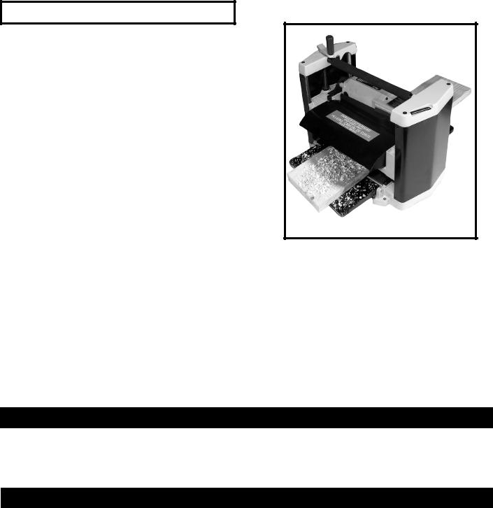
MACHINE USE
When using your machine, follow these few simple steps |
Fig. 26 |
for achieving the best results. |
|
1.True Up One Face – Feed one face of the board over a jointer, making thin cuts with each pass, until the entire surface is flat.
2.Plane to Thickness – Place the side you planed in STEP 1 face down and feed the board through the planer, (Fig. 26). Plane until this side is flat, then plane both sides of the board until you are satisfied with the thickness. Make thin cuts, and alternate sides with each pass. If, during the planing operation, you notice the board twisting, warping, or bowing, repeat STEP 1 and true up one face.
3.When planing long stock, provide table extensions to support the infeed and outfeed end of the workpiece.
4.Plane with the grain only, and keep planer table clean. Occasionally, wax the table surface to reduce friction during the planing operation.
5.Cross-cut to Final Length – Cross-cut lumber to final length.
 The knives on the planer will not wear evenly if the wood is fed through the same spot on the table every time. Feed the wood through the planer at different spots on the table to help eliminate uneven wear of the knives.
TROUBLESHOOTING
For assistance with your machine, visit our website at www.deltamachinery.com for a list of service centers or call the DELTA Machinery help line at 1-800-223-7278 (In Canada call 1-800-463-3582).
MAINTENANCE
KEEP MACHINE CLEAN
Periodically blow out all air passages with dry compressed air. All plastic parts should be cleaned with a soft damp cloth. NEVER use solvents to clean plastic parts. They could possibly dissolve or otherwise damage the material.
 Wear certified safety equipment for eye, hearing and respiratory protection while using compressed air.
FAILURE TO START
Should your machine fail to start, check to make sure the prongs on the cord plug are making good contact in the outlet. Also, check for blown fuses or open circuit breakers in the line.
LUBRICATION & RUST PROTECTION
Apply household floor paste wax to the machine table, extension table or other work surface weekly. Or use a commercially available protective product designed for this purpose. Follow the manufacturer’s instructions for use and safety.
To clean cast iron tables of rust, you will need the following materials: a sheet of medium Scotch-Brite™ Blending Hand Pad, a can of WD-40® and a can of degreaser. Apply the WD-40 and polish the table surface with the Scotch-Brite pad. Degrease the table, then apply the protective product as described above.
14
BRUSH INSPECTION AND REPLACEMENT
 Disconnect tool from power source
Brush life varies. It depends on the load on the motor. Check the brushes after the first 50 hours of use for a new machine or after a new set of brushes has been installed. After the first check, examine them after about 10 hours of use until such time that replacement is necessary.
The brush holders, one of which is shown at (A) Fig. 27, are located on the motor housing opposite each other. One of the brushes, removed for inspection, is illustrated in Fig. 28. When the carbon (B) on either brush is worn to 3/16" in length or if either spring (C) or shunt wire is burned or damaged in any way, replace both brushes. If the brushes are found serviceable after removing, reinstall them in the same position as removed.
 After brush maintenance is completed, the cutterhead guard must be re-installed before starting the planer.
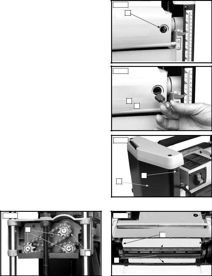
LUBRICATION
The gears in the gear box and the feed roller bushings should be lubricated periodically.
 Disconnect tool from power source.
1.Remove the screw (A) Fig. 29, and nut located on the other end of screw. Remove the side cover (B) from the left side of the planer.
2.Place a light coat of E.P. multi-purpose grease on the teeth of the gears (C) Fig. 30, and a light coat of spray lubricant on the chains (F). Replace the side cover.
3.Place the planer on its back and squirt oil on the feed roller bushings (D) Fig. 31 at each end of the feed rollers (E).
Fig. 30
C
F
Fig. 27
A
Fig. 28
B
C 
Fig. 29
A
B
Fig. 31
D 
E
15
 Loading...