


43-424

INSTRUCTION MANUAL
DATED 7-12-00 PART NO. 432-02-651-0018
© Delta Machinery 2000
Platinum Edition 2-Speed
Heavy-Duty Wood Shaper
(Model 43-424)

2
SAFETY RULES
Woodworking can be dangerous if safe and proper operating procedures are not followed. As with all machinery, there are certain
hazards involved with the operation of the product. Using the machine with respect and caution will considerably lessen the
possibility of personal injury. However, if normal safety precautions are overlooked or ignored, personal injury to the operator may
result. Safety equipment such as guards, push sticks, hold-downs, featherboards, goggles, dust masks and hearing protection can
reduce your potential for injury. But even the best guard won’t make up for poor judgment, carelessness or inattention. Always use
common sense and exercise caution in the workshop. If a procedure feels dangerous, don’t try it. Figure out an alternative procedure
that feels safer. REMEMBER: Your personal safety is your responsibility.
This machine was designed for certain applications only. Delta Machinery strongly recommends that this machine not be modified
and/or used for any application other than that for which it was designed. If you have any questions relative to a particular
application, DO NOT use the machine until you have first contacted Delta to determine if it can or should be performed on the
product.
Technical Service Manager
Delta Machinery
4825 Highway 45 North
P.O. Box 2468
Jackson, TN 38302-2468
(IN CANADA: 505 Southgate Drive, GUELPH, ONTARIO N1H 6M7)
WARNING: FAILURE TO FOLLOW THESE RULES
MAY RESULT IN SERIOUS PERSONAL INJURY
1. FOR YOUR OWN SAFETY, READ INSTRUCTION
MANUAL BEFORE OPERATING THE TOOL. Learn the tool’s
application and limitations as well as the specific hazards
peculiar to it.
2. KEEP GUARDS IN PLACE and in working order.
3. ALWAYS WEAR EYE PROTECTION.
4. GROUND ALL TOOLS. If tool is equipped with three-
prong plug, it should be plugged into a three-hole electrical
receptacle. If an adapter is used to accommodate a two-prong
receptacle, the adapter lug must be attached to a known
ground. Never remove the third prong.
5. REMOVE ADJUSTING KEYS AND WRENCHES. Form
habit of checking to see that keys and adjusting wrenches are
removed from tool before turning it “on.”
6. KEEP WORK AREA CLEAN. Cluttered areas and
benches invite accidents.
7. DON’T USE IN DANGEROUS ENVIRONMENT. Don’t use
power tools in damp or wet locations, or expose them to rain.
Keep work area well-lighted.
8. KEEP CHILDREN AND VISITORS AWAY. All children and
visitors should be kept a safe distance from work area.
9. MAKE WORKSHOP CHILDPROOF – with padlocks,
master switches, or by removing starter keys.
10. DON’T FORCE TOOL. It will do the job better and be safer
at the rate for which it was designed.
11. USE RIGHT TOOL. Don’t force tool or attachment to do a
job for which it was not designed.
12. WEAR PROPER APPAREL. No loose clothing, gloves,
neckties, rings, bracelets, or other jewelry to get caught in
moving parts. Nonslip footwear is recommended. Wear
protective hair covering to contain long hair.
13. ALWAYS USE SAFETY GLASSES. Wear safety glasses.
Everyday eyeglasses only have impact resistant lenses; they
are not safety glasses. Also use face or dust mask if cutting
operation is dusty.
14. SECURE WORK. Use clamps or a vise to hold work when
practical. It’s safer than using your hand and frees both hands
to operate tool.
15. DON’T OVERREACH. Keep proper footing and balance at
all times.
16. MAINTAIN TOOLS IN TOP CONDITION. Keep tools
sharp and clean for best and safest performance. Follow
instructions for lubricating and changing accessories.
17. DISCONNECT TOOLS before servicing and when
changing accessories such as blades, bits, cutters, etc.
18. USE RECOMMENDED ACCESSORIES. The use of
accessories and attachments not recommended by Delta may
cause hazards or risk of injury to persons.
19. REDUCE THE RISK OF UNINTENTIONAL STARTING.
Make sure switch is in “OFF” position before plugging in power
cord.
20. NEVER STAND ON TOOL. Serious injury could occur if
the tool is tipped or if the cutting tool is accidentally
contacted.
21. CHECK DAMAGED PARTS. Before further use of the tool,
a guard or other part that is damaged should be carefully
checked to ensure that it will operate properly and
perform its intended function – check for alignment of moving
parts, binding of moving parts, breakage of parts, mounting,
and any other conditions that may affect its operation. A guard
or other part that is damaged should be properly repaired or
replaced.
22. DIRECTION OF FEED. Feed work into a blade or cutter
against the direction of rotation of the blade or cutter only.
23.
NEVER LEAVE TOOL RUNNING UNATTENDED. TURN
POWER OFF
. Don’t leave tool until it comes to a complete stop.
24. DRUGS, ALCOHOL, MEDICATION. Do not operate tool
while under the influence of drugs, alcohol or any
medication.
25. MAKE SURE TOOL IS DISCONNECTED FROM POWER
SUPPLY
while motor is being mounted, connected or re-
connected.
26. WHEN THE TOOL IS NOT IN USE, the switch should be
locked in the OFF position to prevent unauthorized use of the
tool.
27. WARNING: SOME DUST CREATED BY POWER
SANDING, SAWING, GRINDING, DRILLING, AND OTHER
CONSTRUCTION ACTIVITIES contains chemicals known to
cause cancer, birth defects or other reproductive harm. Some
examples of these chemicals are:
• lead from lead-based paints,
• crystalline silica from bricks and cement and other
masonry products, and
• arsenic and chromium from chemically-treated lumber.
Your risk from these exposures varies, depending on how often
you do this type of work. To reduce your exposure to these
chemicals: work in a well ventilated area, and work with
approved safety equipment, such as those dust masks that are
3
ADDITIONAL SAFETY RULES FOR WOOD SHAPERS
1. WARNING: DO NOT OPERATE YOUR WOOD
SHAPER UNTIL IT IS COMPLETELY ASSEMBLED AND
INSTALLED ACCORDING TO THE INSTRUCTIONS.
2. IF YOU ARE NOT thoroughly familiar with the
operation of Wood Shapers, obtain advice from your
supervisor, instructor or other qualified person.
3. MAKE SURE wiring codes and recommended
electrical connections are followed and that machine is
properly grounded.
4. NEVER turn the shaper “ON” before clearing the
table of all objects (tools, scraps of wood, etc.).
5. DO NOT process materials less than 12" in length or
4 in width without special supporting fixtures. Use push
sticks, featherboards or holddowns whenever possible.
6. ALWAYS use a miter gage and clamp attachment
when edge shaping work less than 6" wide. The fence
should be removed during this operation.
7. AVOID awkward hand positions where a sudden slip
could allow your hand to contact the cutter.
8. KEEP hands away from cutting tool.
9. NEVER run the stock between the fence and the
cutter.
10. DO NOT feed material that is warped, contains
knots or is embedded with foreign objects, such as nails
or
staples.
11. NEVER start the shaper with the stock in contact
with the cutter.
12. NEVER reach under the table while the machine is
running.
13. NEVER perform layout, assembly or set-up work on
the table while the shaper is operating.
14. KEEP cutters sharp and free from rust and pitch.
15. THE FENCE halves should be adjusted so that the
cutter opening is never more than is required to clear the
cutter.
16. ALWAYS lock fence hardware after making fence
adjustments.
17. MAKE CERTAIN cutters are properly secured before
starting machine.
18. DO NOT perform any operation freehand. ALWAYS
use fence for straight shaping; miter gage for edge
shaping; and starting pin and rub collars for curve
shaping.
19. ALWAYS keep front motor access panel closed
while operating shaper.
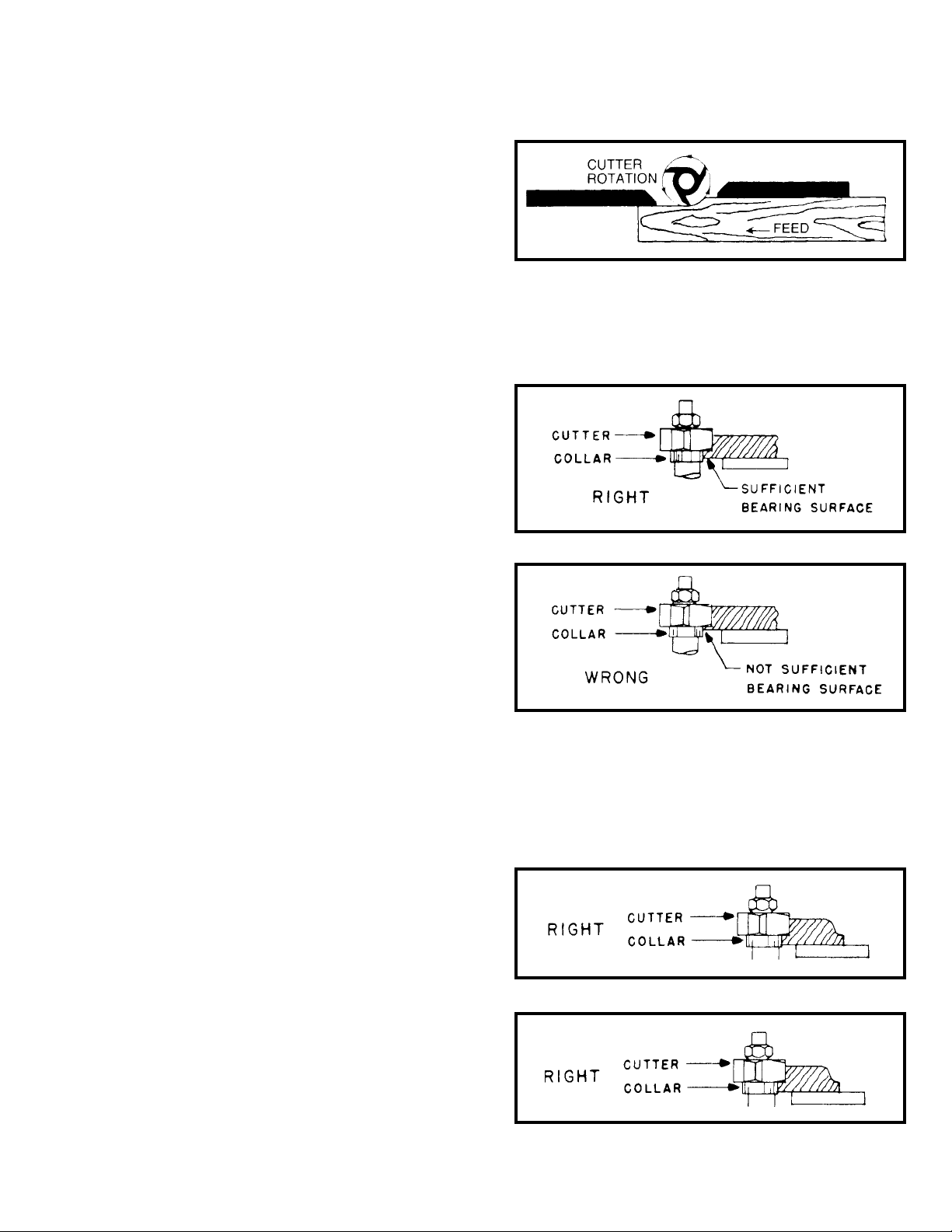
20. ALWAYS feed against the cutter rotation, as shown
in Fig. A.
21. WHEN SHAPING with collars and starting pin, the
collar MUST have sufficient bearing surface, as shown in
Fig. B. Fig. C, illustrates the wrong way for this operation
as the collar DOES NOT have sufficient bearing surface.
Fig. A
Fig. B
Fig. C
22. WHEN SHAPING with collars and starting pin, the
work must be fairly heavy in proportion to the cut being
made as shown in Fig. D. UNDER NO CIRCUMSTANCES
should short work of light body be shaped against the
collars as shown in Fig. E.
Fig. D
Fig. E
4
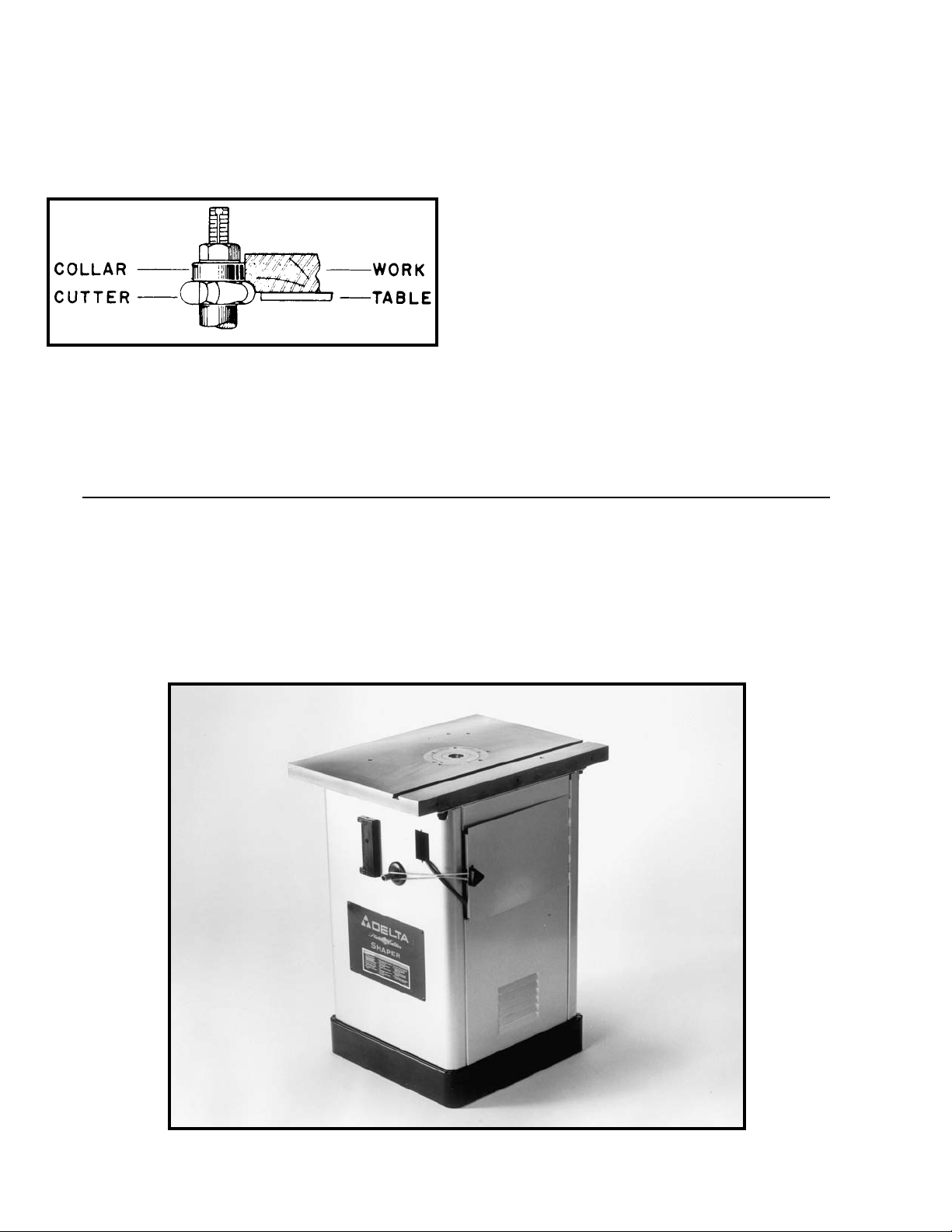
UNPACKING AND CLEANING
Carefully unpack the shaper and fence system from the shipping containers. Clean all loose parts and
remove the protective coating from the machined surfaces of the shaper table. This coating may be removed
with a soft cloth moistened with kerosene (do not use acetone, gasoline, or lacquer thinner for this purpose).
Figures 2 and 3, illustrate the shaper and all loose items supplied with the machine. Fig. 4, illustrates the
items supplied with the fence system.
ADDITIONAL SAFETY RULES FOR WOOD SHAPERS
(continued)
23. WHEN SHAPING with collars and starting pin, the
cutter should be positioned below the collar whenever
possible, as shown in Fig. F.
Fig. F
24. MAKE all adjustments with the power “OFF”.
25. KEEP guard in place at all times.
26. BEFORE leaving the machine, make sure the work
area is clean.
27. SHOULD any part of your shaper be missing,
damaged or fail in any way, or any electrical component
fail to perform properly, shut off switch and remove plug
from power supply outlet. Replace missing, damaged or
failed parts before resuming operation.
28. ADDITIONAL INFORMATION regarding the safe
and proper operation of this product is available from the
National Safety Council, 1121 Spring Lake Drive, Itasca,
IL 60143-3201, in the Accident Prevention Manual for
Industrial Operations and also in the Safety Data Sheets
provided by the NSC. Please also refer to the American
National Standards Institute ANSI 01.1 Safety Require-
ments for Woodworking Machinery and the U.S. Depart-
ment of Labor OSHA 1912.213 Regulations.
29. SAVE THESE INSTRUCTIONS. Refer to them often
and use them to instruct others.
Fig. 2

5
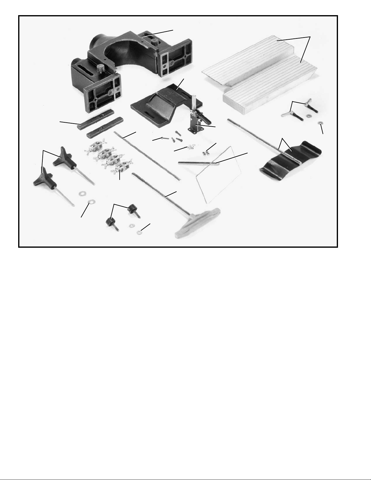
4. 10" Wide Cast Iron Extension Wings
5. Wrenches (2)
6. 7/16-20 x 1" Hex Cap Screws (6) for mounting
extension wings
7. Flat Washers (6) for mounting extension wings
8. Handwheel
9. Key for Handwheel
10. Lock Knob
11. Guard
12. 3/4" I.D. Washer (2)
13. 3/4" I.D. x 1/2" Thick Collar
14. 3/4" I.D. x 3/4" Thick Collar
15. 3/4" I.D. x 1" Thick Collar
16. Spindle Nut
17. Keyed Washer
18. Spindle
19. Tie Rod
20. Tie Rod Nut
21. Keps Nut (2) for mounting switch-to-switch
mounting bracket
22. Phillips Head Screw (2) for mounting
switch-to-switch mounting bracket
23. Flange Nut (4) for mounting switch mounting
bracket to shaper
24. Truss Head Machine Screw (4) for mounting
switch mounting bracket to shaper
25. Switch Adapter Plate (2) for mounting switch
mounting bracket to shaper
26. Starting Pin
Fig. 3
4
5
6
7
16
13
14
15
17
18
19
20
12
11
10
9
8
21
22
23
24
26
25
6
27. Fence Body
28. Left and Right fence halves
29. Locking Levers (2) for fence halves
30. Flat Washers (2) for locking levers
31. Spring clamp for fence guard
32. Top cover
33. Guard Mounting Bracket
34. Clear Plastic Guard
35. Hex Nuts (4) for mounting guard mounting bracket
to top cover
36. Lock Washers (8) for mounting guard mounting
bracket to top cover
37. Hex Soc. Hd. Screw (4) for mounting guard
mounting bracket to top cover
38. Rod for fence guard
39. Holddown for fence guard
40. Brackets for fence guard (4)
41. Flat washers (2) for mounting top cover to fence
body
42. Lock Knobs (2) for mounting top cover to fence
body
43. Flat Washers (2) for fence locking handles
44. Fence Locking Handles (2) for mounting fence
to shaper
45. Lock Bars (23) for fence halves
Fig. 4
27
28
29
30
31
34
35
36
37
38
39
41
42
40
43
44
45
32
33
7
ASSEMBLY INSTRUCTIONS
WARNING: FOR YOUR OWN SAFETY, DO NOT CONNECT THE SHAPER TO THE POWER SOURCE
UNTIL THE SHAPER IS COMPLETELY ASSEMBLED AND YOU HAVE READ AND UNDERSTOOD THE
ENTIRE INSTRUCTION MANUAL.
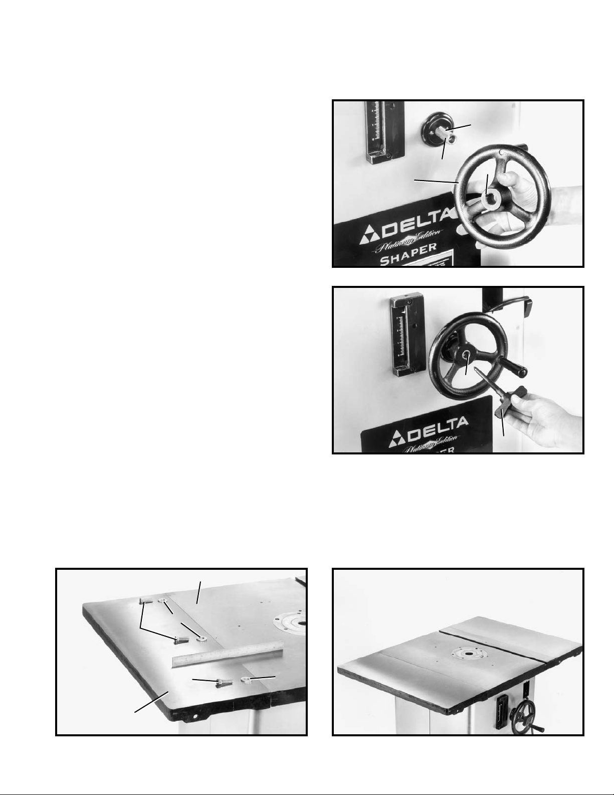
Fig. 5
Fig. 6
Fig. 8Fig. 7
ASSEMBLING SPINDLE
RAISING AND
LOWERING HANDWHEEL
1. Insert key (A) Fig. 5, into slot in spindle raising and
lowering shaft (B) as shown.
2. Assemble handwheel (C) Fig. 5, onto spindle shaft
(B), making certain the key (A) fits into the slot (D) in the
handwheel. Insert the set screw which holds the
handwheel to the shaft and tighten screw firmly against
key.
3. Thread lock knob (E) Fig. 6, into the spindle shaft (B).
ASSEMBLING EXTENSION WINGS TO SHAPER TABLE
1. Assemble extension wing (A) Fig. 7, to shaper table (B) using three 1-1/4" inch-long hex head screws (C) and flat
washers (D) supplied. Use a straight edge (E) Fig. 7, to make certain the extension wing is level with shaper table before
tightening three screws (C). Assemble and level remaining extension wing in the same manner.
2. Fig. 8, illustrates both extension wings assembled to shaper table.
A
B
C
D
B
E
D
C
A
C
D
B
8
Fig. 9 Fig. 10
Fig. 11
Fig. 13
Fig. 12
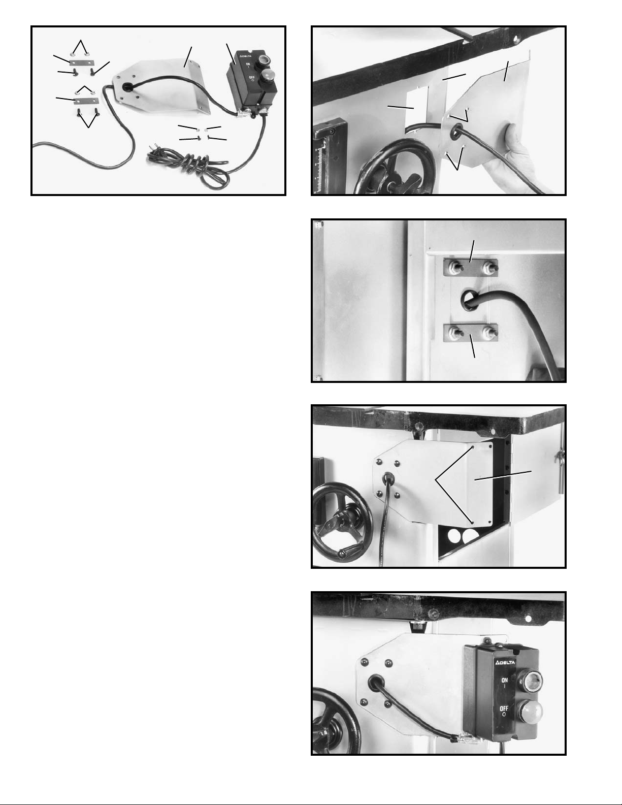
ASSEMBLING
SWITCH BRACKET
AND ON/OFF SWITCH
1. The on/off switch (A) Fig. 9, and switch mounting
bracket (B) are shipped inside the shaper cabinet. Open
the side door of the shaper cabinet, remove switch
package and remove packaging material.
2. Position switch mounting bracket (B) Fig. 10, so
holes (C) are over hole (D) in shaper cabinet (E), then
fasten bracket (B) to cabinet (E) using four truss head
screws (F) Fig. 9, flange nuts (G) and two switch adapter
plates (H). NOTE: Switch adapter plates (H) are to be
positioned inside the shaper cabinet as shown in Fig.
11.
3. Fig. 12, illustrates switch mounting bracket (B)
properly mounted to shaper cabinet.
4. Assemble on/off switch (A) Fig. 9, to switch
mounting bracket (B) Fig. 12, through two holes (J),
using two Phillips head screws (K) Fig. 9, and Keps nuts
(L).
5. Fig. 13, illustrates on/off switch properly mounted to
switch mounting bracket.
G
F
H
F
G
H
F
B
A
L
L
K K
B
D
E
C
C
H
H
B
J
9
Fig. 14
Fig. 16
Fig. 17
Fig. 18
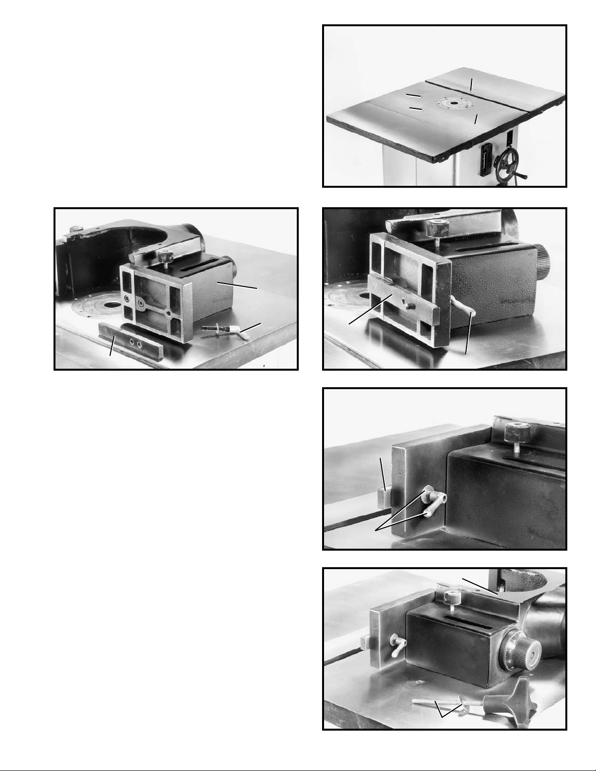
ASSEMBLING FENCE
TO SHAPER TABLE
1. The fence on this shaper can be mounted parallel
to the miter gage slot using two holes (B) Fig. 14, or
90 degrees to the miter slot by using two holes (A). The
following illustrates mounting the fence parallel to the
miter gage.
2. Place fence body (C) Fig. 15, on the table as shown,
and locate the two fence locking levers with washers (D)
and fence lock bars (E).
3. Fasten bar (E) to the front of the fence half using the
locking lever and washers (D), as shown in Figs. 16 and
17. Assemble the remaining bar to the other fence half in
the same manner. NOTE: Locking levers (D) are spring-
loaded and can be repositioned by pulling out the
handle and repositioning it on the nut located
underneath the hub of the handle.
Fig. 15
4. Locate the two fence locking handles and washers,
one of which is shown at (F) Fig. 18, and fasten fence
body (C) to one of the set of holes located on the shaper
table illustrated in Fig. 14.
A
B
A
B
C
E
E
D
E
D
C
F
D
 Loading...