


6" Professional Jointer
(Model 37-195) (Model 37-275X)
PART NO. 909995 - 01-22-03
Copyright © 2003 Delta Machinery
To learn more about DELTA MACHINERY
visit our website at: www.deltamachinery.com.
For Parts, Service, Warranty or other Assistance,
please call 1-800-223-7278 (In Canada call 1-800-463-3582).
MANUAL INSTRUCTION

SAFETY GUIDELINES / DEFINITIONS
This manual contains information that is important for you to know and understand. This information relates to protecting YOUR SAFETY and PREVENTING EQUIPMENT PROBLEMS. To help you recognize this information, we use the symbols to the right. Please read the manual and pay attention to these sections.
 Indicates an imminently hazardous situation which, if not avoided, will result in death or serious injury. Indicates a potentially hazardous situation which, if not avoided, could result in death or serious injury.
Indicates a potentially hazardous situation which, if not avoided, may result in minor or moderate injury
Used without the safety alert symbol indicates potentially hazardous situation which, if not avoided, may result in property damage.
 SOME DUST CREATED BY POWER SANDING, SAWING, GRINDING, DRILLING, AND OTHER CONSTRUCTION ACTIVITIES contains chemicals known to cause cancer, birth defects or other reproductive harm. Some examples of these chemicals are:
·lead from lead-based paints,
·crystalline silica from bricks and cement and other masonry products, and
·arsenic and chromium from chemically-treated lumber.
Your risk from these exposures varies, depending on how often you do this type of work. To reduce your exposure to these chemicals: work in a well ventilated area, and work with approved safety equipment, such as those dust masks that are specially designed to filter out microscopic particles.
GENERAL SAFETY RULES
Woodworking can be dangerous if safe and proper operating procedures are not followed. As with all machinery, there are certain hazards involved with the operation of the product. Using the machine with respect and caution will considerably lessen the possibility of personal injury. However, if normal safety precautions are overlooked or ignored, personal injury to the operator may result. Safety equipment such as guards, push sticks, hold-downs, featherboards, goggles, dust masks and hearing protection can reduce your potential for injury. But even the best guard won’t make up for poor judgment, carelessness or inattention. Always use common sense and exercise caution in the workshop. If a procedure feels dangerous, don’t try it. Figure out an alternative procedure that feels safer. REMEMBER: Your personal safety is your responsibility.
This machine was designed for certain applications only. Delta Machinery strongly recommends that this machine not be modified and/or used for any application other than that for which it was designed. If you have any questions relative to a particular application, DO NOT use the machine until you have first contacted Delta to determine if it can or should be performed on the product.
Technical Service Manager Delta Machinery
4825 Highway 45 North Jackson, TN 38305
(IN CANADA: 505 SOUTHGATE DRIVE, GUELPH, ONTARIO N1H 6M7)
Read Operator’s Manual. Do not operate equipment until you have read Operator’s Manual for Safety,
Assembly, Operation, and Maintenance Instructions.
FAILURE TO FOLLOW THESE RULES MAY RESULT IN SERIOUS PERSONAL INJURY
1.FOR YOUR OWN SAFETY, READ INSTRUCTION MANUAL BEFORE OPERATING THE TOOL. Learn the tool’s application and limitations as well as the specific hazards peculiar to it.
2.KEEP GUARDS IN PLACE and in working order.
3.ALWAYS WEAR EYE PROTECTION. Wear safety glasses. Everyday eyeglasses only have impact resistant lenses; they are not safety glasses. Also use face or dust mask if cutting operation is dusty. These safety glasses must conform to ANSI Z87.1 requirements. NOTE: Approved glasses have Z87 printed or stamped on them.
4.REMOVE ADJUSTING KEYS AND WRENCHES. Form habit of checking to see that keys and adjusting wrenches
are removed from tool before turning it “on”.
5.KEEP WORK AREA CLEAN. Cluttered areas and benches invite accidents.
6.DON’T USE IN DANGEROUS ENVIRONMENT. Don’t use power tools in damp or wet locations, or expose them to rain. Keep work area well-lighted.
7.KEEP CHILDREN AND VISITORS AWAY. All children and visitors should be kept a safe distance from work area.
8.MAKE WORKSHOP CHILDPROOF – with padlocks, master switches, or by removing starter keys.
9. DON’T FORCE TOOL. It will do the job better and be safer at the rate for which it was designed.
10.USE RIGHT TOOL. Don’t force tool or attachment to do a job for which it was not designed.
11.WEAR PROPER APPAREL. No loose clothing, gloves, neckties, rings, bracelets, or other jewelry to get caught in moving parts. Nonslip footwear is recommended. Wear protective hair covering to contain long hair.
12.SECURE WORK. Use clamps or a vise to hold work when practical. It’s safer than using your hand and frees both hands to operate tool.
13.DON’T OVERREACH. Keep proper footing and balance at all times.
14.MAINTAIN TOOLS IN TOP CONDITION. Keep tools sharp and clean for best and safest performance. Follow instructions for lubricating and changing accessories.
15.DISCONNECT TOOLS before servicing and when changing accessories such as blades, bits, cutters, etc.
16.USE RECOMMENDED ACCESSORIES. The use of accessories and attachments not recommended by Delta may cause hazards or risk of injury to persons.
2

17.REDUCE THE RISK OF UNINTENTIONAL STARTING. Make sure switch is in “OFF” position before plugging in power cord. In the event of a power failure, move switch to the “OFF” position.
18.NEVER STAND ON TOOL. Serious injury could occur if the tool is tipped or if the cutting tool is accidentally contacted.
19.CHECK DAMAGED PARTS. Before further use of the tool, a guard or other part that is damaged should be carefully checked to ensure that it will operate properly and perform its intended function – check for alignment of moving parts, binding of moving parts, breakage of parts, mounting, and any other conditions that may affect its operation. A guard or other part that is damaged should be properly repaired or replaced.
20.DIRECTION OF FEED. Feed work into a blade or cutter against the direction of rotation of the blade or cutter only.
21.NEVER LEAVE TOOL RUNNING UNATTENDED. TURN POWER OFF. Don’t leave tool until it comes to a complete stop.
22.STAY ALERT, WATCH WHAT YOU ARE DOING, AND USE COMMON SENSE WHEN OPERATING A POWER TOOL. DO NOT USE TOOL WHILE TIRED OR UNDER THE INFLUENCE OF DRUGS, ALCOHOL, OR MEDICATION. A moment of inattention while operating power tools may result in serious personal injury.
23.MAKE SURE TOOL IS DISCONNECTED FROM POWER SUPPLY while motor is being mounted, connected or reconnected.
24.THE DUST GENERATED by certain woods and wood products can be injurious to your health. Always operate machinery in well ventilated areas and provide for proper dust removal. Use wood dust collection systems whenever possible.
ADDITIONAL SAFETY RULES FOR JOINTERS
FAILURE TO FOLLOW THESE RULES MAY RESULT IN SERIOUS PERSONAL INJURY.
1.WARNING: Do not operate the jointer until it is completely assembled and installed according to the instructions.
2.IF YOU ARE NOT thoroughly familiar with the operation of jointers, obtain advice from your supervisor, instructor or other qualified person.
3.KEEP cutterhead sharp and free of all rust and pitch.
4.BEFORE starting machine, check cutterhead guard to make sure it is not damaged and operates freely.
5.ALWAYS make sure exposed cutterhead behind the fence is guarded, especially when jointing near the edge.
6.NEVER perform jointing or surfacing operations with the cutterhead guard removed.
7.MAKE CERTAIN the infeed and outfeed tables are tightened before starting the machine.
8.NEVER start the jointer with the workpiece contacting the cutterhead.
9.ALWAYS hold the workpiece firmly against the tables and fence.
10.NEVER perform any operation “Free-hand” which means using your hands to support or guide the workpiece. ALWAYS use the fence to position and guide the work.
11.AVOID awkward operations and hand positions where a sudden slip could cause your hand to move into the cutterhead.
12.ALWAYS use hold-down/push blocks for jointing material less than 3 inches in height or surfacing material thinner than 3 inches.
13.DO NOT perform jointing operations on material shorter than 10 inches, narrower than 3/4 inch or less than 1/2 inch thick.
14.DO NOT perform surfacing operations on material shorter than 10 inches, narrower than 3/4 inch, wider than 6 inches or less than 1/2 inch thick.
15.NEVER make jointing or surfacing cuts deeper than 1/8 inch. On cuts more than 1-1/2 inches wide, adjust depth of cut to 1/16 inch or less to avoid overloading machine and to minimize chance of kick-back (work thrown back toward you).
16.MAINTAIN the proper relationship of infeed and outfeed table surfaces and cutterhead knife path.
17.SUPPORT the workpiece adequately at all times during operation; maintain control of the work at all times.
18.DO NOT back the workpiece toward the infeed table.
19.DO NOT attempt to perform an abnormal or littleused operation without study and the use of adequate hold-down/push blocks, jigs, fixtures, stops, push blocks, etc.
20.SHUT OFF power before servicing or adjusting jointer.
21.DISCONNECT jointer from power source and clean the machine before leaving it.
22.MAKE SURE the work area is clean before leaving the machine.
23.SHOULD any part of your jointer be missing, damaged, or fail in any way, or any electrical component fail to perform properly, shut off switch and remove plug from power supply outlet. Replace missing, damaged or failed parts before resuming operation.
24.THE USE of attachments and accessories not recommended by Delta may result in the risk of injuries.
25.ADDITIONAL INFORMATION regarding the safe and proper operation of this product is available from the National Safety Council, 1121 Spring Lake Drive, Itasca, IL 60143-3201 in the Accident Prevention Manual for Industrial Operation and also in the Safety Data Sheets provided by the NSC. Please also refer to the American National Standard Institute ANSI 01.1 Safety Requirements for Woodworking Machinery and the U.S. Department of Labor OSHA 1910.213 Regulations.
SAVE THESE INSTRUCTIONS. Refer to them often
and use them to instruct others.
3
POWER CONNECTIONS
A separate electrical circuit should be used for your machines. This circuit should not be less than #12 wire and should be protected with a 20 Amp time lag fuse. If an extension cord is used, use only 3-wire extension cords which have 3- prong grounding type plugs and matching receptacle which will accept the machine’s plug. Before connecting the machine to the power line, make sure the switch is in the “OFF” position and be sure that the electric current is of the same characteristics as indicated on the machine. All line connections should make good contact. Running on low voltage will damage the machine.
 DO NOT EXPOSE THE MACHINE TO RAIN OR OPERATE THE MACHINE IN DAMP LOCATIONS.
MOTOR SPECIFICATIONS
Your machine is wired for 120 volt, 60 HZ alternating current. Before connecting the machine to the power source, make sure the switch is in the “OFF” position.
GROUNDING INSTRUCTIONS
 THIS MACHINE MUST BE GROUNDED WHILE IN USE TO PROTECT THE OPERATOR FROM ELECTRIC SHOCK.
1. All grounded, cord-connected machines:
In the event of a malfunction or breakdown, grounding provides a path of least resistance for electric current to reduce the risk of electric shock. This machine is equipped with an electric cord having an equipmentgrounding conductor and a grounding plug. The plug must be plugged into a matching outlet that is properly installed and grounded in accordance with all local codes and ordinances.
Do not modify the plug provided - if it will not fit the outlet, have the proper outlet installed by a qualified electrician.
Improper connection of the equipment-grounding conductor can result in risk of electric shock. The conductor with insulation having an outer surface that is green with or without yellow stripes is the equipmentgrounding conductor. If repair or replacement of the electric cord or plug is necessary, do not connect the equipment-grounding conductor to a live terminal.
Check with a qualified electrician or service personnel if the grounding instructions are not completely understood, or if in doubt as to whether the machine is properly grounded.
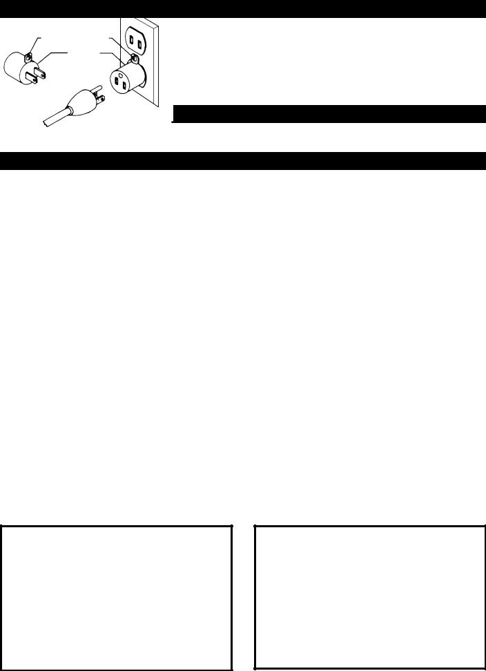
Use only 3-wire extension cords that have 3-prong grounding type plugs and matching 3-conductor receptacles that accept the machine’s plug, as shown in Fig. A.
Repair or replace damaged or worn cord immediately.
GROUNDED OUTLET BOX
CURRENT
CARRYING
PRONGS
2. Grounded, cord-connected machines intended for use on a supply circuit having a nominal rating less than 150 volts:
If the machine is intended for use on a circuit that has an outlet that looks like the one illustrated in Fig. A, the machine will have a grounding plug that looks like the plug illustrated in Fig. A. A temporary adapter, which looks like the adapter illustrated in Fig. B, may be used to connect this plug to a matching 2-conductor receptacle as shown in Fig. B if a properly grounded outlet is not available. The temporary adapter should be used only until a properly grounded outlet can be installed by a qualified electrician. The green-colored rigid ear, lug, and the like, extending from the adapter must be connected to a permanent ground such as a properly grounded outlet box. Whenever the adapter is used, it must be held in place with a metal screw.
NOTE: In Canada, the use of a temporary adapter is not permitted by the Canadian Electric Code.
3. Grounded, cord-connected machines intended for use on a supply circuit having a nominal rating between 150 - 250 volts, inclusive:
If the machine is intended for use on a circuit that has an outlet that looks like the one illustrated in Fig. C, the machine will have a grounding plug that looks like the plug illustrated in Fig. C. Make sure the machine is connected to an outlet having the same configuration as
GROUNDED OUTLET BOX
GROUNDING
MEANS
ADAPTER
GROUNDING BLADE
IS LONGEST OF THE 3 BLADES
Fig. A |
Fig. B |
4
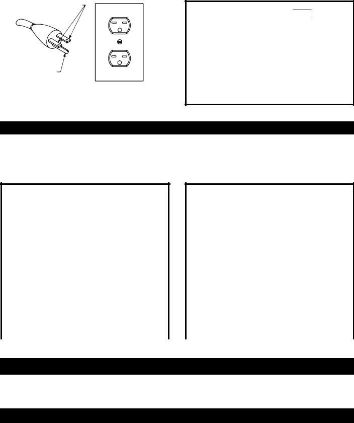
the plug. No adapter is available or should be used with this machine. If the machine must be re-connected for use on a different type of electric circuit, the reconnection should be made by qualified service personnel; and after re-connection, the machine should comply with all local codes and ordinances.
 I N A L L C A S E S , M A K E C E RTA I N THE RECEPTACLE IN QUESTION IS PROPERLY GROUNDED. IF YOU ARE NOT SURE HAVE A Q U A L I F I E D E L E C T R I C I A N C H E C K T H E RECEPTACLE.
GROUNDED OUTLET BOX
CURRENT
CARRYING
PRONGS
GROUNDING BLADE
IS LONGEST OF THE 3 BLADES
Fig. C
EXTENSION CORDS
 Use proper extension cords. Make sure your extension cord is in good condition and is a 3-wire extension cord which has a 3-prong grounding type plug and matching receptacle which will accept the machine’s plug. When using an extension cord, be sure to use one heavy enough to carry the current of the machine. An undersized cord will cause a drop in line voltage, resulting in loss of power and overheating. Fig. D, shows the correct gauge to use depending on the cord length. If in doubt, use the next heavier gauge. The smaller the gauge number, the heavier the cord.
MINIMUM GAUGE EXTENSION CORD
RECOMMENDED SIZES FOR USE WITH STATIONARY ELECTRIC MACHINES
Ampere |
|
Total Length |
Gauge of |
Rating |
Volts |
of Cord in Feet |
Extension Cord |
|
|
|
|
0-6 |
120 |
up to 25 |
18 AWG |
0-6 |
120 |
25-50 |
16 AWG |
0-6 |
120 |
50-100 |
16 AWG |
0-6 |
120 |
100-150 |
14 AWG |
6-10 |
120 |
up to 25 |
18 AWG |
6-10 |
120 |
25-50 |
16 AWG |
6-10 |
120 |
50-100 |
14 AWG |
6-10 |
120 |
100-150 |
12 AWG |
|
|
|
|
10-12 |
120 |
up to 25 |
16 AWG |
10-12 |
120 |
25-50 |
16 AWG |
10-12 |
120 |
50-100 |
14 AWG |
10-12 |
120 |
100-150 |
12 AWG |
12-16 |
120 |
up to 25 |
14 AWG |
12-16 |
120 |
25-50 |
12 AWG |
12-16 |
120 |
GREATER THAN 50 FEET NOT RECOMMENDED |
|
|
|
|
|
Fig. D
MINIMUM GAUGE EXTENSION CORD
RECOMMENDED SIZES FOR USE WITH STATIONARY ELECTRIC MACHINES
Ampere |
|
Total Length |
Gauge of |
Rating |
Volts |
of Cord in Feet |
Extension Cord |
|
|
|
|
0-6 |
240 |
up to 50 |
18 AWG |
0-6 |
240 |
50-100 |
16 AWG |
0-6 |
240 |
100-200 |
16 AWG |
0-6 |
240 |
200-300 |
14 AWG |
6-10 |
240 |
up to 50 |
18 AWG |
6-10 |
240 |
50-100 |
16 AWG |
6-10 |
240 |
100-200 |
14 AWG |
6-10 |
240 |
200-300 |
12 AWG |
|
|
|
|
10-12 |
240 |
up to 50 |
16 AWG |
10-12 |
240 |
50-100 |
16 AWG |
10-12 |
240 |
100-200 |
14 AWG |
10-12 |
240 |
200-300 |
12 AWG |
12-16 |
240 |
up to 50 |
14 AWG |
12-16 |
240 |
50-100 |
12 AWG |
12-16 |
240 |
GREATER THAN 100 FEET NOT RECOMMENDED |
|
|
|
|
|
Fig. D
OPERATING INSTRUCTIONS
FOREWORD
Delta Model 37-195 is a 6" Professional Jointer with a cutting capacity of 6-1/8" (156mm) width, 1/8" depth (3mm max.) and 1/2" (13mm) rabbeting. Unit includes; heavy-duty 1 hp, 120/240 volt induction motor, stand, dust chute, fence, threeknife cutterhead, cutterhead guard, and push blocks.
UNPACKING AND CLEANING
Carefully unpack the machine and all loose items from the shipping container(s). Remove the protective coating from all unpainted surfaces. This coating may be removed with a soft cloth moistened with kerosene (do not use acetone, gasoline or lacquer thinner for this purpose). After cleaning, cover the unpainted surfaces with a good quality household floor paste wax.
NOTICE: THE MANUAL COVER PHOTO ILLUSTRATES THE CURRENT PRODUCTION MODEL. ALL OTHER ILLUSTRATIONS ARE REPRESENTATIVE ONLY AND MAY NOT DEPICT THE ACTUAL COLOR, LABELING OR ACCESSORIES AND MAY BE INTENDED TO ILLUSTRATE TECHNIQUE ONLY.
5

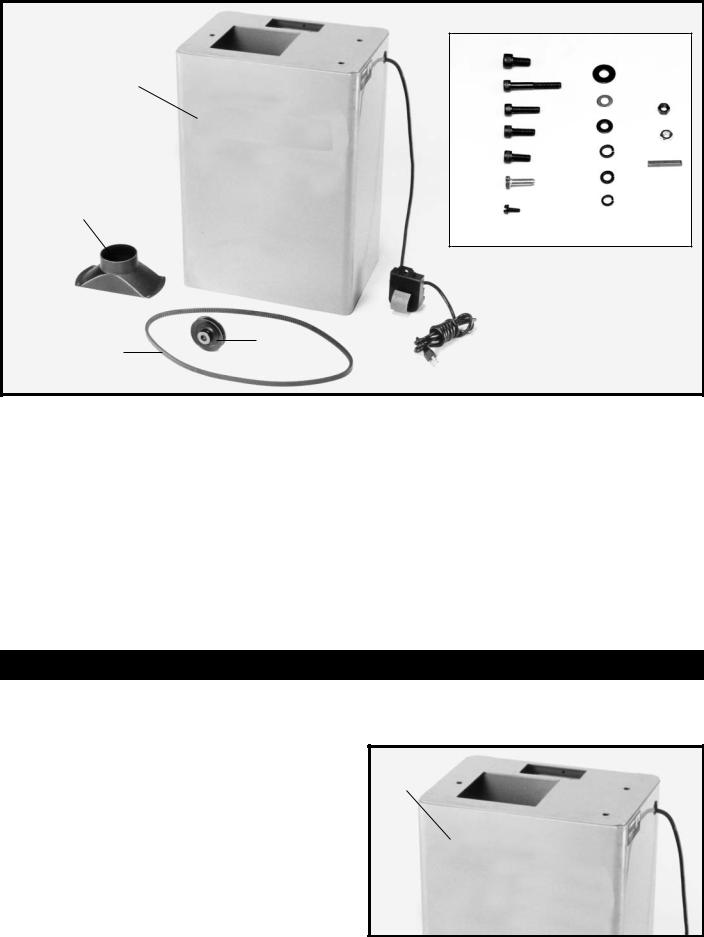
JOINTER PARTS
1
2
3
4 
5
6
7
|
8 |
|
|
|
|
|
|
|
9 |
11 |
|
||||
|
|
|
|
|
|
12 |
|
|
|
|
|
|
|
||
|
|
|
|
13 |
|
||
|
|
14 |
15 |
|
|||
|
|
|
|||||
|
10 |
|
|
|
|
|
|
|
|
|
|
|
|
|
|
|
|
|
|
|
|
Fig. 4 |
|
1. |
Jointer |
9. |
12-14mm Open End Wrench |
||||
2. |
Fence Carriage Assembly |
10. |
8-10mm Open End Wrench |
||||
3. |
Cutterhead Pulley Guard/Carriage Mounting |
11. |
8mm Hex Wrench |
||||
Bracket |
12. |
6mm Hex Wrench |
|||||
|
|
|
|
||||
4. |
Switch Mounting Bracket |
13. |
4mm Hex Wrench |
||||
|
|
|
|
||||
5. |
Cutterhead Guard |
14. |
3mm Hex Wrench |
||||
|
|
|
|
||||
6. |
Fence Tilting Handles (2) |
15. |
2.5mm Hex Wrench |
||||
|
|
|
|
||||
7.Fence
8.Push Blocks (2)
6
|
20 |
|
|
|
|
|
|
|
|
|
|
|
|
|
|
16 |
27 |
|
|
|
|
|
|
|
|
||||||
21 |
|
|
|
|
|
|
|
|
|
||||||
|
|
|
|
|
|
|
|
|
|||||||
|
|
|
|
|
|
|
|
|
|
|
|
|
|
||
|
28 |
|
|
|
|
|
|
|
|
||||||
|
22 |
|
|
|
|
|
|
|
|
|
|||||
|
|
33 |
|
|
|
|
|||||||||
|
|
|
29 |
|
|
|
|
||||||||
|
23 |
|
|
|
|
|
|
|
|
|
|
||||
|
|
|
34 |
|
|
|
|
||||||||
|
|
|
|
|
30 |
|
|
|
|
||||||
|
24 |
|
|
|
|
|
|
|
|
||||||
|
|
|
|
|
|
|
|
|
|
|
|
||||
|
|
|
|
|
35 |
|
|
|
|
||||||
|
|
|
|
|
|
31 |
|
|
|
|
|||||
|
25 |
|
|
|
|
|
|
|
|
|
|||||
|
|
|
|
|
|
|
|
|
|
|
|
||||
|
|
32 |
|
|
|
|
|
|
|
|
|||||
17 |
26 |
|
|
|
|
|
|
|
|
|
|||||
|
|
|
|
|
|
|
|
|
|||||||
|
|
|
|
|
|
|
|
|
|
|
|
|
|
||
|
|
|
|
|
|
|
|
|
|
|
|
|
|
|
|
19
18
|
|
Fig. 5 |
|
16. |
Stand with Pre-Wired Switch |
26. |
#10-16x1/2" Sheet Metal Screw (4) |
17. |
Dust Chute |
27. |
M10 Flat Washer (3) |
18. |
V-Belt |
28. |
11/32" Flat Washer (1) |
19. |
Pulley |
29. |
M8 Flat Washer (10) |
20. |
M10x1.5x20mm Hex Socket Head Screw (3) |
30. |
M10.2 Lockwasher (3) |
21. |
M8x1.25x55mm Hex Socket Head Screw (4) |
31. |
M8.1 Lockwasher (10) |
22. |
M8x1.25x30mm Hex Socket Head Screw (2) |
32. |
5/16" Lockwasher (1) |
23. |
M8x1.25x25mm Hex Socket Head Screw (2) |
33. |
M8x1.25 Hex Nut (2) |
24. |
M8x1.25x20mm Hex Socket Head Screw (2) |
34. |
5/16-18 Hex Nut (1) |
25. |
5/16-18x1" Hex Head Screw (1) |
35. |
Key |
ASSEMBLY
 FOR YOUR OWN SAFETY, DO NOT CONNECT THE MACHINE TO THE POWER SOURCE UNTIL THE MACHINE IS COMPLETELY ASSEMBLED AND YOU READ AND UNDERSTAND THE ENTIRE INSTRUCTION MANUAL.
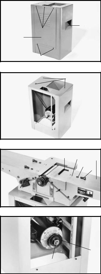
STAND AND ELECTRICALS
Your Jointer stand (A) Fig. 6, is shipped with the motor |
A |
|
|
and switch completely wired, and the motor mounted. |
|
Fig. 6
7
ASSEMBLING
JOINTER TO STAND
1.The outfeed end (N) Fig. 9, of the jointer must be pointing toward the end of the stand with dust chute opening (B) Fig. 7.
2.Remove three screws (C) Fig. 7, and loosen two screws (D). Then remove back panel (E) from stand by lifting upward.
3. Line up the three holes (F) Fig. 8, on the top of stand with the three threaded holes on the bottom of the jointer base. Using the supplied 8mm hex wrench (G) Fig. 9, fasten the jointer to the stand. Place a M10.2 lockwasher (I), on a M10x1.5x20mm hex socket head screw (H), and a M10 flat washer onto the screw. Insert the screw through the hole in the stand and thread the screw into the tapped hole in the bottom of the jointer, and tighten securely. Repeat this process for the two remaining holes in the stand and the jointer. NOTE: The mounting hole located on the dust chute end of the stand is accessed by reaching up through the dust chute.
ASSEMBLING
MOTOR PULLEY
Assemble motor pulley (K) Fig. 10, to motor shaft with the hub of the pulley in the outer position as shown. Make certain key (L) is inserted in the keyway of the pulley and motor shaft, then tighten set screw (M) using the 2.5mm hex wrench (not shown).
B
C
E
D
Fig. 7
F
Fig. 8
G J N
I
H
Fig. 9
M  K
K
L
Fig. 10
8
 Loading...