


12" Radial Arm Saw
(Model 33-890) 33-891) 33-892)
PART NO. 424-02-651-0023 (018)
Copyright © 2001 Delta Machinery
To learn more about DELTA MACHINERY
visit our website at: www.deltamachinery.com.
For Parts, Service, Warranty or other Assistance,
please call 1-800-223-7278 (In Canada call 1-800-463-3582).
MANUAL INSTRUCTION

GENERAL SAFETY RULES
Woodworking can be dangerous if safe and proper operating procedures are not followed. As with all machinery, there are certain hazards involved with the operation of the product. Using the machine with respect and caution will considerably lessen the possibility of personal injury. However, if normal safety precautions are overlooked or ignored, personal injury to the operator may result. Safety equipment such as guards, push sticks, hold-downs, featherboards, goggles, dust masks and hearing protection can reduce your potential for injury. But even the best guard won’t make up for poor judgment, carelessness or inattention. Always use common sense and exercise caution in the workshop. If a procedure feels dangerous, don’t try it. Figure out an alternative procedure that feels safer. REMEMBER: Your personal safety is your responsibility.
This machine was designed for certain applications only. Delta Machinery strongly recommends that this machine not be modified and/or used for any application other than that for which it was designed. If you have any questions relative to a particular application, DO NOT use the machine until you have first contacted Delta to determine if it can or should be performed on the product.
Technical Service Manager Delta Machinery
4825 Highway 45 North Jackson, TN 38305
(IN CANADA: 505 SOUTHGATE DRIVE, GUELPH, ONTARIO N1H 6M7)
WARNING: FAILURE TO FOLLOW THESE RULES MAY RESULT IN SERIOUS PERSONAL INJURY
1.FOR YOUR OWN SAFETY, READ INSTRUCTION MANUAL BEFORE OPERATING THE TOOL. Learn the tool’s application and limitations as well as the specific hazards peculiar to it.
2.KEEP GUARDS IN PLACE and in working order.
3.ALWAYS WEAR EYE PROTECTION. Wear safety glasses. Everyday eyeglasses only have impact resistant lenses; they are not safety glasses. Also use face or dust mask if cutting operation is dusty. These safety glasses must conform to ANSI Z87.1 requirements. NOTE: Approved glasses have Z87 printed or stamped on them.
4.REMOVE ADJUSTING KEYS AND WRENCHES. Form habit of checking to see that keys and adjusting wrenches
are removed from tool before turning it “on”.
5.KEEP WORK AREA CLEAN. Cluttered areas and benches invite accidents.
6.DON’T USE IN DANGEROUS ENVIRONMENT. Don’t use power tools in damp or wet locations, or expose them to rain. Keep work area well-lighted.
7.KEEP CHILDREN AND VISITORS AWAY. All children and visitors should be kept a safe distance from work area.
8.MAKE WORKSHOP CHILDPROOF – with padlocks, master switches, or by removing starter keys.
9.DON’T FORCE TOOL. It will do the job better and be safer at the rate for which it was designed.
10.USE RIGHT TOOL. Don’t force tool or attachment to do a job for which it was not designed.
11.WEAR PROPER APPAREL. No loose clothing, gloves, neckties, rings, bracelets, or other jewelry to get caught in moving parts. Nonslip footwear is recommended. Wear protective hair covering to contain long hair.
12.SECURE WORK. Use clamps or a vise to hold work when practical. It’s safer than using your hand and frees both hands to operate tool.
13.DON’T OVERREACH. Keep proper footing and balance at all times.
14.MAINTAIN TOOLS IN TOP CONDITION. Keep tools sharp and clean for best and safest performance. Follow instructions for lubricating and changing accessories.
15.DISCONNECT TOOLS before servicing and when changing accessories such as blades, bits, cutters, etc.
16.USE RECOMMENDED ACCESSORIES. The use of accessories and attachments not recommended by Delta may cause hazards or risk of injury to persons.
17.REDUCE THE RISK OF UNINTENTIONAL STARTING. Make sure switch is in “OFF” position before plugging in power cord. In the event of a power failure, move switch to the “OFF” position.
18.NEVER STAND ON TOOL. Serious injury could occur if the tool is tipped or if the cutting tool is accidentally contacted.
19.CHECK DAMAGED PARTS. Before further use of the tool, a guard or other part that is damaged should be carefully checked to ensure that it will operate properly and perform its intended function – check for alignment of moving parts, binding of moving parts, breakage of parts, mounting, and any other conditions that may affect its operation. A guard or other part that is damaged should be properly repaired or replaced.
20.DIRECTION OF FEED. Feed work into a blade or cutter against the direction of rotation of the blade or cutter only.
21.NEVER LEAVE TOOL RUNNING UNATTENDED. TURN POWER OFF. Don’t leave tool until it comes to a complete stop.
22.STAY ALERT, WATCH WHAT YOU ARE DOING, AND USE COMMON SENSE WHEN OPERATING A POWER TOOL. DO NOT USE TOOL WHILE TIRED OR UNDER THE INFLUENCE OF DRUGS, ALCOHOL, OR MEDICATION. A moment of inattention while operating power tools may result in serious personal injury.
23.MAKE SURE TOOL IS DISCONNECTED FROM POWER SUPPLY while motor is being mounted, connected or reconnected.
24.THE DUST GENERATED by certain woods and wood products can be injurious to your health. Always operate machinery in well ventilated areas and provide for proper dust removal. Use wood dust collection systems whenever possible.
25. WARNING: SOME DUST CREATED BY POWER SANDING, SAWING, GRINDING, DRILLING, AND OTHER CONSTRUCTION ACTIVITIES contains chemicals known to cause cancer, birth defects or other reproductive harm. Some examples of these chemicals are:
· lead from lead-based paints,
· crystalline silica from bricks and cement and other masonry products, and
· arsenic and chromium from chemically-treated lumber. Your risk from these exposures varies, depending on how often you do this type of work. To reduce your exposure to these chemicals: work in a well ventilated area, and work with approved safety equipment, such as those dust masks that are specially designed to filter out microscopic particles.
SAVE THESE INSTRUCTIONS.
Refer to them often and use them to instruct others.
2

ADDITIONAL SAFETY RULES FOR
RADIAL ARM SAWS
WARNING: FAILURE TO FOLLOW THESE RULES MAY RESULT IN SERIOUS PERSONAL INJURY
1.IF YOU ARE NOT thoroughly familiar with the operation for Radial Saws, obtain advice from your supervisor, instructor, or other qualified person.
2.MAKE SURE wiring codes and recommended electrical connections are followed and that machine is properly grounded.
3.KEEP saw blade sharp and free of all rust and pitch.
4.KEEP blade and arbor flanges free from dirt and grease.
5.MAKE SURE end plate is securely fastened to track arm before using saw.
6.BE SURE that all clamp handles are properly tightened before operating machine.
7.DO NOT perform any cutting operation freehand, that is without using the fence to support or guide the work.
8.WHEN FINISHED cross-cutting, always return the cutting-head to the rear of the track arm.
9.ALWAYS follow warning on saw guard for instructions on ripping to be absolutely certain of not ripping from the wrong end.
10.KNOW HOW to reduce the risk of kickback. Always use anti-kickback fingers when ripping. The guard should be lowered on the in-feed end and the antikickback attachment adjusted accordingly.
11.NEVER feed work into the anti-kickback end of the machine.
12.ALWAYS turn off power and wait until saw blade stops turning before moving workpiece or changing operational settings.
13.SHUT OFF the power and do not leave until the blade has come to a complete stop.
14.DIRECTION OF FEED. On ripping operations, feed work into the blade or cutter against the direction of rotation of the blade or cutter only.
15.ALWAYS use push-stick when ripping narrow work.
16.KEEP hands out of path of saw blade.
17.NEVER reach around or in back of saw blade.
18.USE only 12" saw blades with a 5/8" arbor hole.
19.DO NOT leave cut-off pieces on the table as they may vibrate into the saw blade and be thrown out. After cutting, turn saw off and remove cut-off pieces only after the blade has come to a complete stop.
20.NEVER start saw with the saw blade engaged in the workpiece.
21.MAKE SURE that long or wide workpieces are properly supported
22.NEVER perform a “crossed arm” operation. Keep arms and hands out of path of saw blade.
23.IMPORTANT: When the tool is not in use, the switch should be locked in the “OFF” position to prevent unauthorized use.
24.ADDITIONAL INFORMATION regarding the safe and proper operation of this product is available from the National Safety Council, 1121 Spring Lake Drive, Itasca, IL 60143-3201, in the Accident Prevention Manual for Industrial Operations and also in the Safety Data Sheets provided by the NSC. Please also refer to the American National Standards Institute ANSI 01.1 Safety Requirements for Woodworking Machinery and the U.S. Department of Labor OSHA 1910.213 Regulations.
3

POWER CONNECTIONS
A separate electrical circuit should be used for your tools. This circuit should not be less than #12 wire and should be protected with a 20 Amp time lag fuse. If an extension cord is used, use only 3-wire extension cords which have 3- prong grounding type plugs and matching receptacle which will accept the tool’s plug. Before connecting the motor to the power line, make sure the switch is in the “OFF” position and be sure that the electric current is of the same characteristics as indicated on the tool. All line connections should make good contact. Running on low voltage will damage the motor.
WARNING: DO NOT EXPOSE THE TOOL TO RAIN OR OPERATE THE TOOL IN DAMP LOCATIONS.
MOTOR SPECIFICATIONS
Your tool is wired for 230 volt, 60 HZ alternating current. Before connecting the tool to the power source, make sure the switch is in the “OFF” position.
SINGLE PHASE MOTOR
The single phase motor is rated for 2 hp, 230 volt, 3450 RPM. Only operate the saw from a power source that is within +10% of 230 volt nameplate rating.
THREE PHASE MOTOR
The three phase motor is rated at 2 hp, 200-230/460 volts, 3450 RPM.
Unless a special order is placed, the saw is shipped ready to run for 200-230 volts operation. Should it be necessary to re-wire your saw for 460 volts, refer to Delta Instruction Manual for 24 volt LVC (Low Voltage Control) Magnetic Motor Control Systems and contact a qualified electrician for proper procedures to convert the saw for 460 volt operation.
GROUNDING INSTRUCTIONS
WARNING: THIS TOOL MUST BE GROUNDED WHILE IN USE TO PROTECT THE OPERATOR FROM ELECTRIC SHOCK.
1. All grounded, cord-connected tools:
In the event of a malfunction or breakdown, grounding provides a path of least resistance for electric current to reduce the risk of electric shock. This tool is equipped with an electric cord having an equipment-grounding conductor and a grounding plug. The plug must be plugged into a matching outlet that is properly installed and grounded in accordance with all local codes and ordinances.
Do not modify the plug provided - if it will not fit the outlet, have the proper outlet installed by a qualified electrician.
Improper connection of the equipment-grounding conductor can result in risk of electric shock. The conductor with insulation having an outer surface that is green with or without yellow stripes is the equipmentgrounding conductor. If repair or replacement of the electric cord or plug is necessary, do not connect the equipment-grounding conductor to a live terminal.
Check with a qualified electrician or service personnel if the grounding instructions are not completely understood, or if in doubt as to whether the tool is properly grounded.
Use only 3-wire extension cords that have 3-prong grounding type plugs and matching 3-conductor receptacles that accept the tool’s plug, as shown in Fig. C.
Repair or replace damaged or worn cord immediately.
2. Grounded, cord-connected tools intended for use on a supply circuit having a nominal rating between 150 - 250 volts, inclusive:
This tool is intended for use on a circuit that has an outlet that looks like the one illustrated in Fig. C. The tool has a grounding plug that looks like the plug illustrated in Fig. C. Make sure the tool is connected to an outlet having the same configuration as the plug. No adapter is available or should be used with this tool. If the tool must be reconnected for use on a different type of electric circuit, the reconnection should be made by qualified service personnel; and after reconnection, the tool should comply with all local codes and ordinances.
 WARNING: IN ALL CASES, MAKE CERTAIN THE RECEPTACLE IN QUESTION IS PROPERLY GROUNDED. IF YOU ARE NOT SURE HAVE A QUALIFIED ELECTRICIAN CHECK THE RECEPTACLE.
GROUNDED OUTLET BOX
CURRENT CARRYING
PRONGS
GROUND PRONG
Fig. C
4

EXTENSION CORDS
Use proper extension cords. Make sure your extension cord is in good condition and is a 3-wire extension cord which has a 3-prong grounding type plug and matching receptacle which will accept the tool’s plug. When using an extension cord, be sure to use one heavy enough to carry the current of the tool. An undersized cord will cause a drop in line voltage, resulting in loss of power and overheating. Fig. D, shows the correct gauge to use depending on the cord length. If in doubt, use the next heavier gauge. The smaller the gauge number, the heavier the cord.
MINIMUM GAUGE EXTENSION CORD
RECOMMENDED SIZES FOR USE WITH STATIONARY ELECTRIC TOOLS
Ampere |
|
Total Length |
Gauge of |
Rating |
Volts |
of Cord in Feet |
Extension Cord |
0-6 |
240 |
up to 50 |
18 AWG |
0-6 |
240 |
50-100 |
16 AWG |
0-6 |
240 |
100-200 |
16 AWG |
0-6 |
240 |
200-300 |
14 AWG |
6-10 |
240 |
up to 50 |
18 AWG |
6-10 |
240 |
50-100 |
16 AWG |
6-10 |
240 |
100-200 |
14 AWG |
6-10 |
240 |
200-300 |
12 AWG |
|
|
|
|
10-12 |
240 |
up to 50 |
16 AWG |
10-12 |
240 |
50-100 |
16 AWG |
10-12 |
240 |
100-200 |
14 AWG |
10-12 |
240 |
200-300 |
12 AWG |
|
|
|
|
12-16 |
240 |
up to 50 |
14 AWG |
12-16 |
240 |
50-100 |
12 AWG |
12-16 |
240 |
GREATER THAN 100 FEET NOT RECOMMENDED |
|
|
|
|
|
Fig. D
OPERATING INSTRUCTIONS
FOREWORD
Delta Model 33-890 12" Radial Arm Saw is built for capacity with versatility. The Delta Model 33-890 has a full 3¾" depth of cut at 90 degrees, and 2½" depth of cut at 45 degrees. The 33-890 can crosscut 14-3/8" in a single pass. The 33-890 has a unique turret arm action which permits the motor assembly to rotate 360 degrees above the work table.
UNPACKING AND CLEANING
Carefully unpack the tool and all loose items from the shipping container(s). Remove the protective coating from all unpainted surfaces. This coating may be removed with a soft cloth moistened with kerosene (do not use acetone, gasoline or lacquer thinner for this purpose). After cleaning, cover the unpainted surfaces with a good quality household floor paste wax.
NOTICE: THE MANUAL COVER PHOTO ILLUSTRATES THE CURRENT PRODUCTION MODEL. ALL OTHER ILLUSTRATIONS ARE REPRESENTATIVE ONLY AND MAY NOT DEPICT THE ACTUAL COLOR, LABELING OR ACCESSORIES.
5
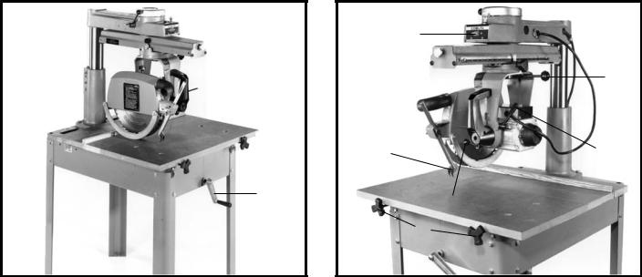
OPERATING CONTROLS
The following is an explanation of the operating controls of the Delta 10” Radial Saw. We suggest you study these explanations carefully to familiarize yourself with the controls before turning on the power, to avoid damage to the saw or personal injury.
A
 M
M
C
 B
B
F
Fig. 2
A – TRACK ARM CLAMP KNOB. Controls swing of track arm for all miter cutting operations. Locks track arm at any angle for the full 360º rotation. To rotate track arm loosen clamp knob and rotate arm. The arm will stop at the 0º and 45º positions right and left. To move the arm past these points the track arm index knob (B) must be pulled out. (Fig. 2)
B – TRACK ARM INDEX KNOB. Locates 0º and 45º position, right and left, of the track arm. (Fig. 2)
C – YOKE INDEX LEVER. Locates each 90º position of the yoke for ripping or cross-cutting operations. When rotating the yoke the yoke clamp handle must first be loose. (Fig. 2)
D – YOKE CLAMP HANDLE. The yoke clamp handle must be loose when rotating the yoke to the rip or crosscut position. (Fig. 3)
E – ANTI-KICKBACK DEVICE. When ripping, the yoke is positioned and clamped so that the blade is parallel to the fence. The rear of the blade guard is lowered until it almost touches the workpiece. The anti-kickback rod is then lowered so that the fingers catch and hold the workpiece. Never rip from the anti-kickback end of the blade guard. (Fig. 3)
L
 G
G
D
E J
H
K
Fig. 3
F – OVERARM ELEVATING HANDLE. Controls the depth of cut in all operations. Turning the handle raises or lowers the overarm. (Fig. 2)
G – CUTTINGHEAD CLAMP KNOB. Locks cuttinghead at any position on the track arm. When ripping the cutting clamp knob must be tight. (Fig. 3)
H – BEVEL INDEX KNOB. Locates 0º and 45º and 90º positions of the motor when bevel cutting. When tilting the motor for bevel cutting, the bevel clamp handle must first be loose. (Fig. 3)
J – BEVEL CLAMP LEVER. Controls tilt of motor for bevel cutting operations. Locks motor at any desired angle on the bevel scale. (Fig. 3)
K – TABLE CLAMP KNOBS. Allows the operator to quickly set the desired fence position. (Fig. 3)
L – ON-OFF SWITCH. Conveniently placed at eye level; switch can be turned on or off in an instant for added
operator protection. (Fig. 3)
M – MITER SCALE. Indicates degrees left and right for setting track arm. (Fig. 2)
6
ASSEMBLY
ASSEMBLING
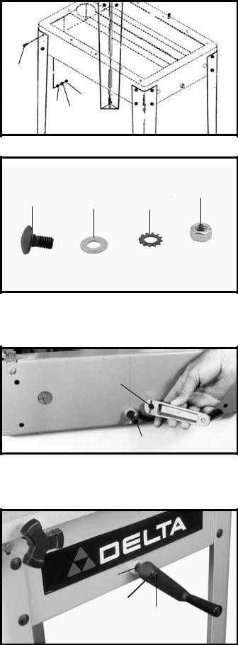
STEEL LEGS TO BASE
Carefully support the machine to the rear and brace the frame so the machine is balanced. Attach the four steel legs to each end of the base using sixteen 5/16-18x5/8" carriage head screws (A) Fig. 4A and Fig. 4B, 5/16" flat washers (B), 5/16" lockwashers (C) and 5/16" hex nuts
(D). Return saw to upright position.
ASSEMBLING OVERARM ELEVATING HANDLE
1.Insert roll pin (A) Fig. 5, into the hole in elevating shaft (B).
2.Line up the slots in elevating handle (C) Fig. 5, with roll pin (A) and place handle on shaft (B) making certain the roll pin is engaged in the slots.
3.Fasten elevating handle (C) Fig. 6, to shaft (B) with a 1/4-20X1/2" hex head screw (D) and 1/4" flat washer
(E).
A
D
B C
Fig. 4A
D
A B C
Fig. 4B
C
A
B
Fig. 5
 C
C
B
E
D
Fig. 6
7

ASSEMBLING
CUTTINGHEAD
TO TRACK ARM
1.Raise the track arm assembly (A) Fig. 7, by turning overarm elevating handle (F) Fig. 2.
2.Remove packing material from around cuttinghead assembly (B) Fig. 7.
3.Push track arm clamp lever (C) Fig. 7, to the rear until it rests against stop (D) as shown.
4.Pull out on track arm index knob (E) Fig. 7, and rotate track arm (F) 90 degrees to the position shown in Fig. 8. Tighten track arm clamp lever (C) Fig. 8, by pulling it to front position.
5.Unscrew and remove blade guard clamping rod (G) Fig. 9, and remove blade guard assembly (H).
6.Place cuttinghead clamp (J) Fig. 10, in slot on top of cuttinghead. NOTE: Jaws of cuttinghead clamp must be open as shown.
7.Lift cuttinghead assembly (B) Fig. 11, and insert roller bearings (K) into track arm assembly (A) as shown. NOTE: Make certain the roller bearings (K) are riding on track rods (L). Push cuttinghead assembly (B) Fig. 11, into track arm assembly (A) and tighten cuttinghead clamp (J) Fig. 11.
J
Fig. 10
C
F
E
D
A
 B
B
Fig. 7
C
F
Fig. 8
G
H
Fig. 9
A
J
B
L K L
Fig. 11
8
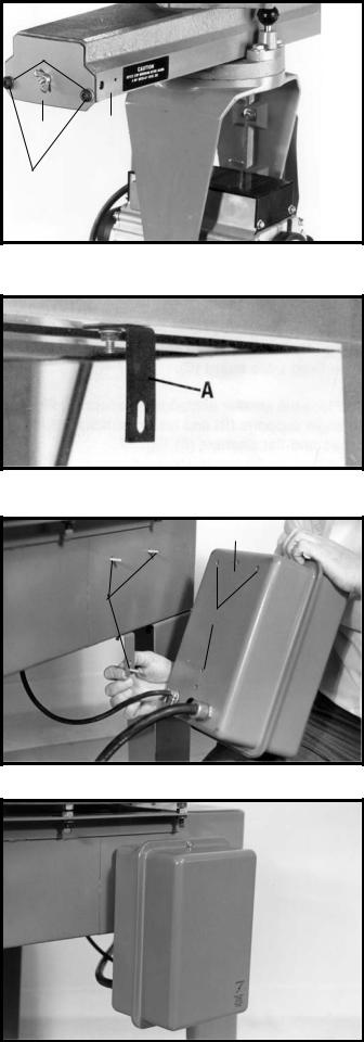
8. Assemble end cap (N) Fig. 12, to the rear of track arm assembly (A) and fasten with two 5/16-18x3/4" button head screws (P) and 5/16" lockwashers (Q) supplied.
ASSEMBLING STARTER BOX TO BASE
If you purchased your machine with magnetic starter, transformer and overload protection, assemble the starter box to the base, as follows:
1.Assemble bracket (A) to the bottom of the right side of saw base, as shown in Fig. 13. Place a 1/4" flat washer onto a 1/4-20x3/4" hex head screw and insert screw through hole in the bottom of the right side of the saw base. Place the bracket (A) Fig. 13 onto the screw, place a 1/4" lock washer onto the screw and thread a 1/4-20 hex nut onto screw and tighten securely.
2.Assemble the starter box (B) Fig. 14, to the right side of the base. Place a 1/4" lockwasher onto a 1/4-20x1/2" hex head screw, place a 1/4" flat washer on the screw and insert the hex head screw (C), through the hole in the in the bracket (E), and thread screw into the weld nut (D) Fig. 14, in the back of the starter box (B). Repeat this process for the two remaining holes in the base and the starter box.
3.Fig. 15, illustrates the starter box assembled to the base.
Q
N A
P
Fig. 12
Fig. 13
B
C
D
 E
E
Fig. 14
Fig. 15
9
 Loading...