


28-206, 28-276
10" Contractors Saw
(Model
 36-978/36-979)
14" Band Saw
Scies à ruban de 355 mm (14 po)
Sierra de Cinta de 14 pulg.
Instruction Manual
Manuel d’utilisation
Manual de instrucciones
FRANÇAIS 26 |
ESPAÑOL 50 |
|
|
www.deltamachinery.com
(800) 223-7278 - US
(800) 463-3582 - CANADA
A20096 - 09-11-06 - Rev. A
Copyright © 2006 Delta Machinery

TABLE OF CONTENTS
IMPORTANT SAFETY INSTRUCTIONS .................... |
2 |
TROUBLESHOOTING ................................................ |
21 |
SAFETY GUIDELINES - DEFINITIONS ..................... |
3 |
MAINTENANCE.......................................................... |
24 |
GENERAL SAFETY RULES ....................................... |
4 |
SERVICE..................................................................... |
24 |
ADDITIONAL SPECIFIC SAFETY RULES ................ |
5 |
ACCESSORIES........................................................... |
25 |
FUNCTIONAL DESCRIPTION ................................... |
7 |
WARRANTY................................................................ |
25 |
CARTON CONTENTS ............................................... |
7 |
FRANÇAIS .................................................................. |
26 |
ASSEMBLY ................................................................. |
10 |
ESPAÑOL.................................................................... |
50 |
OPERATION ............................................................... |
16 |
|
|
IMPORTANT SAFETY INSTRUCTIONS
 Read and understand all warnings and operating instructions before using any tool or equipment. When using tools or equipment, basic safety precautions should always be followed to reduce the risk of personal injury. Improper operation, maintenance or modification of tools or equipment could result in serious injury and property damage. There are certain applications for which
tools and equipment are designed. Delta Machinery strongly recommends that this product NOT be modified and/or used for any application other than for which it was designed.
If you have any questions relative to its application DO NOT use the product until you have written Delta Machinery and we have advised you. Contact us online at www.deltamachinery.com or by mail at Technical Service Manager, Delta Machinery, 4825 Highway 45 North, Jackson, TN 38305. In Canada,125 Mural St. Suite 300, Richmond Hill, ON, L4B 1M4)
Information regarding the safe and proper operation of this tool is available from the following sources:
•Power Tool Institute, 1300 Sumner Avenue, Cleveland, OH 44115-2851or online at www.powertoolinstitute.org
•National Safety Council, 1121 Spring Lake Drive, Itasca, IL 60143-3201
•American National Standards Institute, 25 West 43rd Street, 4 floor, New York, NY 10036 www.ansi.org - ANSI 01.1 Safety Requirements for Woodworking Machines
•U.S. Department of Labor regulations www.osha.gov
SAVE THESE INSTRUCTIONS!
SAFETY GUIDELINES - DEFINITIONS
It is important for you to read and understand this manual. The information it contains relates to protecting YOUR SAFETY and PREVENTING PROBLEMS. The symbols below are used to help you recognize this information.
Indicates an imminently hazardous situation which, if not avoided, will result in death or serious injury.
Indicates a potentially hazardous situation which, if not avoided, could result in death or serious injury.
Indicates a potentially hazardous situation which, if not avoided, may result in minor or moderate injury.
Used without the safety alert symbol indicates a potentially hazardous situation which, if not avoided, may result in property damage.
CALIFORNIA PROPOSITION 65
Some dust created by power sanding, sawing, grinding, drilling, and other construction activities contains chemicals known to cause cancer, birth defects or other reproductive harm. Some
examples of these chemicals are:
•lead from lead-based paints,
•crystalline silica from bricks and cement and other masonry products, and
•arsenic and chromium from chemically-treated lumber.
Your risk from these exposures varies, depending on how often you do this type of work. To reduce your exposure to these chemicals: work in a well ventilated area, and work with approved safety equipment, always wear NIOSH/OSHA approved, properly fitting face mask or respirator when using such tools.
2 - English

GENERAL SAFETY RULES
 Failure to follow these rules may result in serious personal injury.
1.FOR YOUR OWN SAFETY, READ THE INSTRUCTION MANUAL BEFORE OPERATING THE MACHINE. Learning the machine’s application, limitations, and specific hazards will greatly minimize the possibility of accidents and injury.
2.WEAR EYE AND HEARING PROTECTION. ALWAYS USE SAFETY GLASSES. Everyday eyeglasses are NOT safety glasses. USE CERTIFIED SAFETY EQUIPMENT. Eye protection equipment should comply with ANSI Z87.1 standards. Hearing equipment should comply with ANSI S3.19 standards.
3.WEAR PROPER APPAREL. Do not wear loose clothing, gloves, neckties, rings, bracelets, or other jewelry which may get caught in moving parts. Nonslip protective footwear is recommended. Wear protective hair covering to contain long hair.
4.DO NOT USE THE MACHINE IN A DANGEROUS ENVIRONMENT. The use of power tools in damp or wet locations or in rain can cause shock or electrocution. Keep your work area well-lit to prevent tripping or placing arms, hands, and fingers in danger.
5.MAINTAIN ALL TOOLS AND MACHINES IN PEAK CONDITION. Keep tools sharp and clean for best and safest performance. Follow instructions for lubricating and changing accessories. Poorly maintained tools and machines can further damage the tool or machine and/or cause injury.
6.CHECK FOR DAMAGED PARTS. Before using the machine, check for any damaged parts. Check for alignment of moving parts, binding of moving parts, breakage of parts, and any other conditions that may affect its operation. A guard or any other part that is damaged should be properly repaired or replaced with Delta or factory authorized replacement parts. Damaged parts can cause further damage to the machine and/or injury.
7.KEEP THE WORK AREA CLEAN. Cluttered areas and benches invite accidents.
8.KEEP CHILDREN AND VISITORS AWAY. Your shop is a potentially dangerous environment. Children and visitors can be injured.
9.REDUCE THE RISK OF UNINTENTIONAL STARTING. Make sure that the switch is in the "OFF" position before plugging in the power cord. In the event of a power failure, move the switch to the "OFF" position. An accidental start-up can cause injury. Do not touch the plug’s metal prongs when unplugging or plugging in the cord.
10.USE THE GUARDS. Check to see that all guards are in place, secured, and working correctly to prevent injury.
11.REMOVE ADJUSTING KEYS AND WRENCHES BEFORE STARTING THE MACHINE. Tools, scrap pieces, and other debris can be thrown at high speed, causing injury.
12.USE THE RIGHT MACHINE. Don’t force a machine or an attachment to do a job for which it was not designed. Damage to the machine and/or injury may result.
13.USE RECOMMENDED ACCESSORIES. The use of accessories and attachments not recommended by Delta may cause damage to the machine or injury to the user.
14.USE THE PROPER EXTENSION CORD. Make sure your extension cord is in good condition. When using an extension cord, be sure to use one heavy enough to carry the current your product will draw. An undersized cord will cause a drop in line voltage, resulting in loss of power and overheating. See the Extension Cord Chart for the correct size depending on the cord length and nameplate ampere rating. If in doubt, use the next heavier gauge. The smaller the gauge number, the heavier the cord.
15.SECURE THE WORKPIECE. Use clamps or a vise to hold the workpiece when practical. Loss of control of a workpiece can cause injury.
16.FEED THE WORKPIECE AGAINST THE DIRECTION OF THE ROTATION OF THE BLADE, CUTTER, OR ABRASIVE SURFACE. Feeding it from the other direction will cause the workpiece to be thrown out at high speed.
17.DON’T FORCE THE WORKPIECE ON THE MACHINE.
Damage to the machine and/or injury may result.
18.DON’T OVERREACH. Loss of balance can make you fall into a working machine, causing injury.
19.NEVER STAND ON THE MACHINE. Injury could occur if the tool tips, or if you accidentally contact the cutting tool.
20.NEVER LEAVE THE MACHINE RUNNING UNATTENDED. TURN THE POWER OFF. Don’t leave the machine until it comes to a complete stop. A child or visitor could be injured.
21.TURN THE MACHINE "OFF", AND DISCONNECT THE MACHINE FROM THE POWER SOURCE before installing or removing accessories, changing cutters, adjusting or changing set-ups. When making repairs, be sure to lock the start switch in the "OFF" position. An accidental start-up can cause injury.
22.MAKE YOUR WORKSHOP CHILDPROOF WITH PADLOCKS, MASTER SWITCHES, OR BY REMOVING STARTER KEYS. The accidental start-up of a machine by a child or visitor could cause injury.
23. STAY ALERT, WATCH WHAT YOU ARE DOING, AND USE
COMMON SENSE. DO NOT USE THE MACHINE WHEN YOU ARE TIRED OR UNDER THE INFLUENCE OF DRUGS, ALCOHOL, OR MEDICATION. A moment of inattention while operating power tools may result in injury.
24.  USE OF THIS TOOL CAN GENERATE AND
DISBURSE DUST OR OTHER AIRBORNE PARTICLES, INCLUDING WOOD DUST, CRYSTALLINE SILICA DUST AND ASBESTOS DUST. Direct particles away from face and body. Always operate tool in well ventilated area and provide for proper dust removal. Use dust collection system wherever possible. Exposure to the dust may cause serious and permanent respiratory or other injury, including silicosis (a serious lung disease), cancer, and death. Avoid breathing the dust, and avoid prolonged contact with dust. Allowing dust to get into your mouth or eyes, or lay on your skin may promote absorption of harmful material. Always use properly fitting NIOSH/OSHA approved respiratory protection appropriate for the dust exposure, and wash exposed areas with soap and water.
3 - English

ADDITIONAL SPECIFIC SAFETY RULES
 Failure to follow these rules may result in serious personal injury.
1.DO NOT OPERATE THIS MACHINE UNTIL it is assembled and installed according to the instructions.
2.OBTAIN ADVICE from your supervisor, instructor, or another qualified person if you are not familiar with the operation of this tool.
3.FOLLOW ALL WIRING CODES and recommended electrical connections.
4.USE THE GUARDS WHENEVER POSSIBLE. Check to see that they are in place, properly adjusted, secured, and working correctly.
5.USE PROPER BLADE SIZE and type.
6.ADJUST THE UPPER BLADE GUIDE so that it is about 1/8" above the workpiece.
7.PROPERLY ADJUST the blade tension, tracking, blade guides, and blade support bearings.
8.KEEP ARMS, HANDS, AND FINGERS away from the blade.
9.AVOID AWKWARD OPERATIONS and hand positions where a sudden slip could cause a hand to move into the blade.
10.NEVER START THE MACHINE before clearing the table of all objects (tools, scrap pieces, etc.).
11.NEVER START THE MACHINE with the workpiece against the blade.
12.HOLD WORKPIECE FIRMLY against the table. DO NOT attempt to saw a workpiece that does not have a flat surface against the table.
13.HOLD WORKPIECE FIRMLY and feed into blade at a moderate speed.
14.NEVER REACH UNDER THE TABLE while the machine is running.
15.TURN THE MACHINE "OFF" to back out of an uncompleted or jammed cut.
16.MAKE "RELIEF" CUTS prior to cutting long curves.
17.TURN THE MACHINE "OFF" and wait for the blade to stop prior to cleaning the blade area, removing debris near the blade, removing or securing workpiece, or changing the angle of the table. A coasting blade can be dangerous.
18.NEVER PERFORM LAYOUT, ASSEMBLY, or set-up work on the table/work area when the machine is running.
19. TURN THE MACHINE "OFF" AND DISCONNECT THE MACHINE from the power source before installing or removing accessories, before adjusting or changing setups, or when making repairs.
20.TURN THE MACHINE "OFF", disconnect the machine from the power source, and clean the table/work area before leaving the machine. LOCK THE SWITCH IN THE "OFF" POSITION to prevent unauthorized use.
21. ADDITIONAL INFORMATION |
regarding the |
safe |
and proper operation of power tools (i.e. a safety |
||
video) is available from the Power Tool Institute, 1300 |
||
Sumner Avenue, Cleveland, |
OH 44115-2851 |
(www. |
powertoolinstitute.com). Information is also available from the National Safety Council, 1121 Spring Lake Drive, Itasca, IL 60143-3201. Please refer to the American National Standards Institute ANSI 01.1 Safety Requirements for Woodworking Machines and the U.S. Department of Labor OSHA 1910.213 Regulations.
SAVE THESE INSTRUCTIONS.
Refer to them often
and use them to instruct others.
4 - English
POWER CONNECTIONS
A separate electrical circuit should be used for your machines. This circuit should not be less than #12 wire and should be protected with a 20 Amp time lag fuse. If an extension cord is used, use only 3-wire extension cords which have 3-prong grounding type plugs and matching receptacle which will accept the machine’s plug. Before connecting the machine to the power line, make sure the switch (s) is in the "OFF" position and be sure that the electric current is of the same characteristics as indicated on the machine. All line connections should make good contact. Running on low voltage will damage the machine.
 Do not expose the machine to rain or operate the machine in damp locations.
MOTOR SPECIFICATIONS
Your machine is wired for 120/240 volts, 60 HZ alternating current. Before connecting the machine to the power source, make sure the switch is in the "OFF" position.
GROUNDING INSTRUCTIONS
 This machine must be grounded while in use to protect the operator from electric shock.
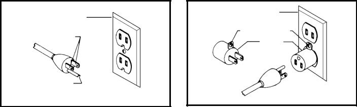
1.All grounded, cord-connected machines:
In the event of a malfunction or breakdown, grounding provides a path of least resistance for electric current to reduce the risk of electric shock. This machine is equipped with an electric cord having an equipment-grounding conductor and a grounding plug. The plug must be plugged into a matching outlet that is properly installed and grounded in accordance with all local codes and ordinances.
Do not modify the plug provided - if it will not fit the outlet, have the proper outlet installed by a qualified electrician.
Improper connection of the equipment-grounding conductor can result in risk of electric shock. The conductor with insulation having an outer surface that is green with or without yellow stripes is the equipment-grounding conductor. If repair or replacement of the electric cord or plug is necessary, do not connect the equipment-grounding conductor to a live terminal.
Check with a qualified electrician or service personnel if the grounding instructions are not completely understood, or if in doubt as to whether the machine is properly grounded.
Use only 3-wire extension cords that have 3-prong grounding type plugs and matching 3-conductor receptacles that accept the machine’s plug, as shown in Fig. A.
Repair or replace damaged or worn cord immediately.
2.Grounded, cord-connected machines intended for use on a supply circuit having a nominal rating less than 150 volts:
If the machine is intended for use on a circuit that has an outlet that looks like the one illustrated in Fig. A, the machine will have a grounding plug that looks like the plug illustrated in Fig. A. A temporary adapter, which looks like the adapter illustrated in Fig. B, may be used to connect this plug to a matching 2-conductor receptacle as shown in Fig. B if a properly grounded outlet is not available. The temporary adapter should be used only until a properly grounded outlet can be installed by a qualified electrician. The green-colored rigid ear, lug, and the like, extending from the adapter must be connected to a permanent ground such as a properly grounded outlet box. Whenever the adapter is used, it must be held in place with a metal screw.
NOTE: In Canada, the use of a temporary adapter is not permitted by the Canadian Electric Code.
 In all cases, make certain that the receptacle in question is properly grounded. If you are not sure, have a qualified electrician check the receptacle.
|
GROUNDED OUTLET BOX |
||
GROUNDED OUTLET BOX |
|
|
|
CURRENT |
GROUNDING MEANS |
||
|
|
|
|
CARRYING |
|
|
|
|
ADAPTER |
|
|
PRONGS |
|
|
|
|
|
|
|
|
|
|
|
IS
GROUNDING BLADE
IS LONGEST OF THE 3 BLADES
Fig. A |
Fig. B |
5 - English
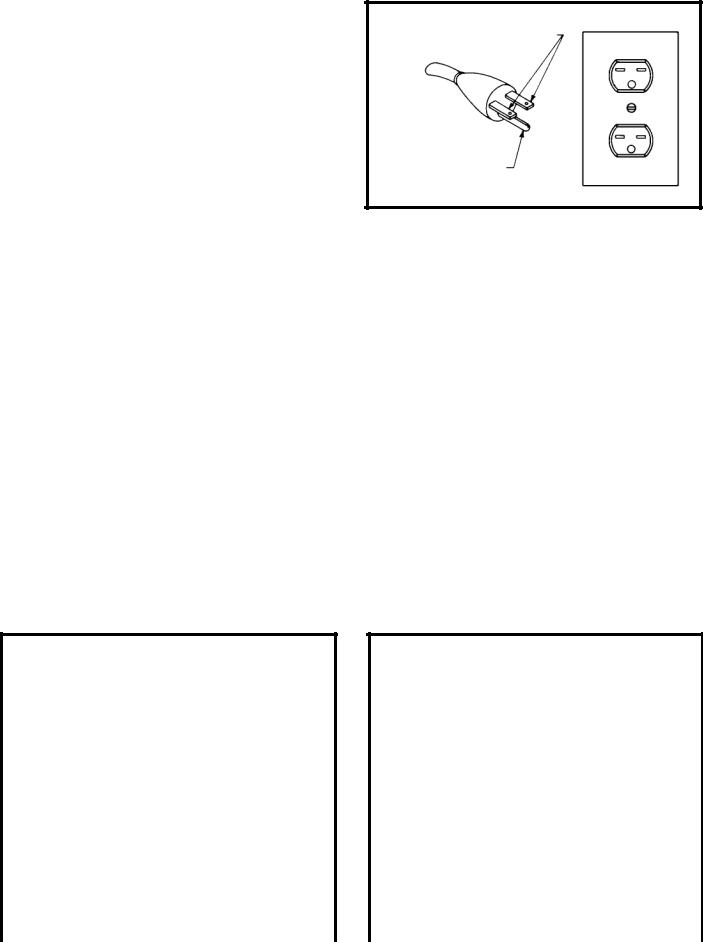
3. 240 VOLT SINGLE PHASE OPERATION
The motor supplied with your machine is a dual voltage, 120/240 volt motor. It is shipped ready- to-run for 120 volt operation. However, it can be converted for 240 volt operation.
A qualified electrician should do the conversion, or the machine can be taken to an Authorized Delta Service Center. When completed, the machine must conform to the National Electric Code and all local codes and ordinances.
The machine is converted by re-wiring the motor for 240 volts, installing a 240 volt plug on the power supply cord and replacing the switch with one that is rated for 240 volt operation.
Be sure the 240 volt plug is only used in an outlet having the same configuration as the plug illustrated in Fig. C. No adapter should be used with the 240 volt plug.
 In all cases, make certain that the receptacle in question is properly grounded. If you are not sure, have a qualified electrician check the receptacle.
GROUNDED OUTLET BOX
CURRENT
CARRYING
PRONGS
GROUNDING BLADE
IS LONGEST OF THE 3 BLADES
Fig. C
EXTENSION CORDS
 Use proper extension cords. Make sure your extension cord is in good condition and is a 3- wire extension cord which has a 3-prong grounding type plug and matching receptacle which will accept the machine’s plug. When using an extension cord, be sure to use one heavy enough to carry the current of the machine. An undersized cord will cause a drop in line voltage, resulting in loss of power and overheating. Fig. D-1 or D-2, shows the correct gauge to use depending on the cord length. If in doubt, use the next heavier gauge. The smaller the gauge number, the heavier the cord.
MINIMUM GAUGE EXTENSION CORD
RECOMMENDED SIZES FOR USE WITH STATIONARY ELECTRIC MACHINES
Ampere |
|
Total Length |
Gauge of |
Rating |
Volts |
of Cord in Feet |
Extension Cord |
|
|
|
|
0-6 |
120 |
up to 25 |
18 AWG |
0-6 |
120 |
25-50 |
16 AWG |
0-6 |
120 |
50-100 |
16 AWG |
0-6 |
120 |
100-150 |
14 AWG |
|
|
|
|
6-10 |
120 |
up to 25 |
18 AWG |
6-10 |
120 |
25-50 |
16 AWG |
6-10 |
120 |
50-100 |
14 AWG |
6-10 |
120 |
100-150 |
12 AWG |
10-12 |
120 |
up to 25 |
16 AWG |
10-12 |
120 |
25-50 |
16 AWG |
10-12 |
120 |
50-100 |
14 AWG |
10-12 |
120 |
100-150 |
12 AWG |
|
|
|
|
12-16 |
120 |
up to 25 |
14 AWG |
12-16 |
120 |
25-50 |
12 AWG |
12-16 |
120 |
GREATER THAN 50 FEET NOT RECOMMENDED |
|
|
|
|
|
Fig. D-1
MINIMUM GAUGE EXTENSION CORD
RECOMMENDED SIZES FOR USE WITH STATIONARY ELECTRIC MACHINES
Ampere |
|
Total Length |
Gauge of |
Rating |
Volts |
of Cord in Feet |
Extension Cord |
|
|
|
|
0-6 |
240 |
up to 50 |
18 AWG |
0-6 |
240 |
50-100 |
16 AWG |
0-6 |
240 |
100-200 |
16 AWG |
0-6 |
240 |
200-300 |
14 AWG |
|
|
|
|
6-10 |
240 |
up to 50 |
18 AWG |
6-10 |
240 |
50-100 |
16 AWG |
6-10 |
240 |
100-200 |
14 AWG |
6-10 |
240 |
200-300 |
12 AWG |
10-12 |
240 |
up to 50 |
16 AWG |
10-12 |
240 |
50-100 |
16 AWG |
10-12 |
240 |
100-200 |
14 AWG |
10-12 |
240 |
200-300 |
12 AWG |
|
|
|
|
12-16 |
240 |
up to 50 |
14 AWG |
12-16 |
240 |
50-100 |
12 AWG |
12-16 |
240 |
GREATER THAN 100 FEET NOT RECOMMENDED |
|
|
|
|
|
Fig. D-2
6 - English

FUNCTIONAL DESCRIPTION
FOREWORD
Model 28-206 is a 1 Hp, 120/240 volt, 2-speed unit with a quick blade-tensioning device and an enclosed stand.
Model 28-276 is a 3/4 Hp, 120/240 volt, 1-speed unit with a quick blade-tensioning device and an open stand.
UNPACKING AND CLEANING
Carefully unpack the machine and all loose items from the shipping container(s). Remove the rust-preventative oil from unpainted surfaces using a soft cloth moistened with mineral spirits, paint thinner or denatured alcohol.
Do not use highly volatile solvents such as gasoline, naphtha, acetone or lacquer thinner for cleaning your machine.
After cleaning, cover the unpainted surfaces with a good quality household floor paste wax.
NOTICE: The photo on the manual cover illustrates the current production model. All other illustrations contained in the manual are representative only and may not depict the actual labeling or accessories included. These are are intended to illustrate technique only.
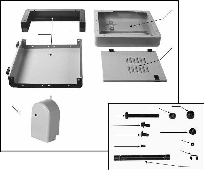
CARTON CONTENTS
1
7 |
8 |
9 |
10 |
|
|
|
|
|
2 |
|
|
|
|
4 |
3 |
|
|
|
|
|
|
|
11 |
|
12 |
|
|
|
|
|
|
5 |
|
|
|
|
|
6 |
|
|
|
|
|
|
|
1. |
Band Saw |
|
7. |
M8x 1.25 x 40mm (4) (for assembling saw to |
|
2. |
Motor |
|
|
stand) |
|
3. |
Table |
|
8. |
M8 Lockwasher (4) (for assembling saw to stand) |
|
4. |
Table Insert |
|
9. |
M8 Flat Washer (4) (for assembling saw to stand) |
|
5. |
Belt |
|
10. |
M8x1.25 Hex nut (4) (for assembling saw to stand) |
|
6. |
Motor Mounting Plate |
11. |
Table Knob (2) |
||
|
|
|
|
12. |
M13 Flat Washer (2) |
7 - English
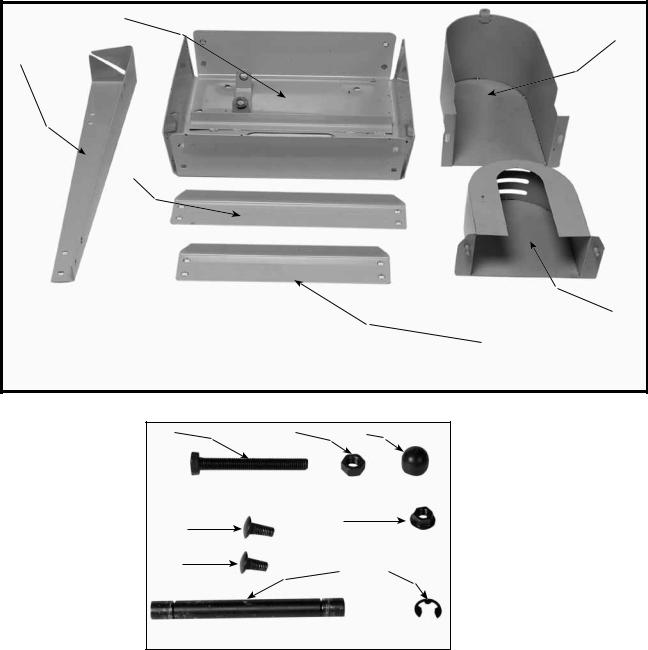
MODEL 28-206 ENCLOSED STAND PARTS
|
|
|
3 |
|
2 |
1 |
|
|
|
|
|
|
|
|
4 |
5 |
|
11 |
12 |
|
|
||
|
|
|
|
|
|
6 |
|
|
|
7 |
|
|
|
8 |
13 |
|
|
14 |
|
|
|
|
|
|
|
9 |
15 |
|
|
|
|
|
|
|
10 |
1. |
Base (2) |
9. |
M5x0.8x10mm Pan Head Screw (2) |
2. |
Side (2) |
10. |
Shaft (for attaching motor plate to top of stand) |
3. |
Stand Top |
11. |
M10 x 1.5 Hex nut |
4. |
Door (2) |
12. |
Dampening Cap |
5. |
Pulley Guard |
13. |
M8x1.25 Hex Flange Nut (30) |
6. |
M10x1.5x100mm Hex Head Screw |
14. |
M5x0.8 Hex Nut (2) |
7. |
M8x1.25x16mm Hex Head Flange Screw (26) |
15. |
9mm C ring (2) |
8. |
M8x1.25x16mm Round Head Flange Screw (4) |
|
|
8 - English
MODEL 28-276 OPEN STAND PARTS
2 |
|
|
|
|
|
|
5 |
1 |
|
|
|
3 |
|
|
|
|
|
|
6 |
|
|
|
4 |
7 |
8 |
9 |
|
10 |
|
12 |
|
|
|
|
|
11 |
|
13 |
14 |
|
|
1. |
Legs (4) |
8. |
M10x1.5 Hex Nut |
2. |
Stand Top |
9. |
Dampening Cap |
3. |
Long Brace (2) |
10. |
M8x1.25x16mm Round Head Flange Screw (4) |
4. |
Short Brace (2) |
11. |
M8x1.25x16mm Carriage Head Screw (32) |
5. |
Upper Pulley Guard |
12. |
M8x1.25 Hex Flange Nut (38) |
6. |
Lower Pulley Guard |
13. |
Shaft (for attaching motor plate to top of stand) |
7. |
M10x1.5x80mm Hex Head Screw |
14. |
9mm C ring (2) |
9 - English
ASSEMBLY
ASSEMBLY TOOLS REQUIRED
13mm OpenEnd Wrench - 8mm Open-End Wrench - Adjustable Wrench
ASSEMBLY TIME ESTIMATE
Assembly for this machine takes 2 hours or less.
For your own safety, do not connect the machine to the power source until the machine is completely assembled and you read and understand the entire instruction manual.
MODEL 28-206 ENCLOSED STAND ASSEMBLY
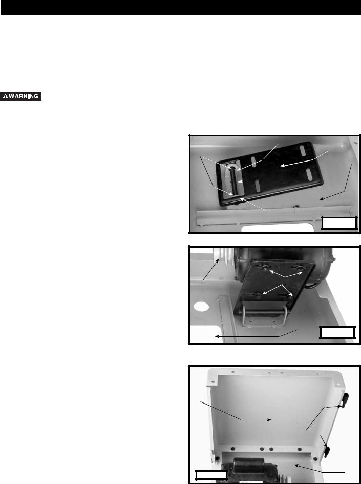
1.Place the stand top (A) Fig. 5 on a flat surface.
2.Align the two holes in the motor mounting plate (E) Fig. 5 with the two holes (B) in the stand top (A).
3.Insert the shaft (D) through the holes in the motor mounting plate and the holes in the stand top.
4.Attach the two "C" rings (C) Fig. 5 on the shaft.
5.Align the four holes on the motor bracket with the four holes (C) Fig. 6 on the motor mounting plate.
NOTE: Confirm that the motor pulley (A) Fig. 6 is mounted on the same side as the belt opening hole
(B).
6.Insert a round head flange screw (M8 x 1.25 x 16mm) through the hole in the motor bracket and the hole in the motor mounting plate.
7.Thread a hex flange nut (M8x1.25) on the screw.
8.Repeat this process for the three remaining holes.
C
E
B
A

 D
D
C
Fig. 5 |
C
A
B
Fig. 6
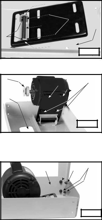
9.Align the holes in the side (A) Fig. 7 with the holes in the stand top (B).
NOTE: Confirm that the hinge catches (C) Fig. 7 are pointed toward the stand top.
10.Insert a hex head flange screw (M8x1.25x16mm) through the hole in the side of the stand and the hole in the top of the stand.
11.Thread a flange nut (M8x1.25)on the screw.
NOTE: Loosely tighten the hardware for further adjustment.
12.Repeat this process for the five remaining holes.
13.Attach the other stand side in the same manner.
A
C 
Fig. 7 |
B |
|
10 - English
14.Align the holes in the base (A) Fig. 8, with the holes in the two sides (B).
15.Insert a hex head flange screw (M8x1.25x16mm) through the hole in the side of the stand (B) Fig. 8, and through the hole in the base (A).
16.Thread a hex flange nut (M8x1.25) on the screw.
NOTE: Loosely tighten the hardware for further adjustment.
17.Repeat this process for the five remaining holes.
18.Attach the other side of the base in the same manner.
19.Attach the two bases together by inserting a hex head flange screw (M8x1.25x16mm) through the hole (C) Fig. 8 in each base, and thread a hex flange nut (M8x1.25) on the screw.
20.Turn the stand over so that it is resting on the base.
21.Slide the two hinges of the door (A) Fig. 9 over the hinge catches (B) on the stand.
22.Close the door until the door latch (C) Fig. 9, engages with the side (D).
23.Attach the other door in the same manner.
24.Thread a hex nut (M10x1.5) on a hex head screw (M10x1.5x100mm) approximately 1/4".
25.Thread the hex head screw (C) into the hole (A) Fig. 10 in the top of the stand.
26.Place the damping cap (A) Fig. 10A on the threaded end of the screw (C).
27.Align the holes (D) Fig. 10 on the hinges attached to the pulley guard with the two holes (B) in the top of the stand.
28.Insert a pan head screw (M5x0.8x10mm) through the hole (D) Fig. 10 in the hinge, and the hole (B) in the top of the stand.
29.Thread a hex nut (M5x0.8) on the screw and tighten securely.
30.Repeat this process for the remaining hole in the hinge and the top of the stand.
31.Confirm that the stand is level.
32.Tighten all hardware securely.
|
A |
|
C |
Fig. 8 |
B |
|
C
D
A 
 B
B
Fig. 9 |
D B
|
C |
A |
Fig. 10 |
|
11 - English
MODEL 28-276 OPEN STAND ASSEMBLY
 For your own safety, do not connect the machine to the power source until the machine is completely assembled and you read and understand the entire instruction manual.
E
1. Place the stand top (A) Fig. 11 on a flat surface.
2. |
Align the two holes in the motor mounting plate (E) |
|
|
Fig. 11 with the two holes (B) in the stand top (A). |
C |
3. |
Insert the shaft (D) through the holes in the motor |
D |
|
mounting plate and the holes in the stand top. |
|
4. |
Attach the two "C" rings (C) Fig. 11 to the shaft. |
B |
|
|
E |
A
Fig. 11 |
5.Align the four holes on the motor bracket with the four holes (C) Fig. 12, on the motor mounting plate.
NOTE: Confirm that the motor pulley (A) Fig. 12 is mounted on the same side and the belt-opening hole (B).
6.Insert a round head flange screw (M8x1.25x16mm) through the hole in the motor bracket and the hole in the motor mounting plate.
7.Thread a hex flange nut (M8x1.25) on the screw.
8.Repeat this process for the three remaining holes.
A
 C
C
B
Fig. 12 |
9.Align the four holes (A) Fig. 13 in the leg with the four holes in the side of the stand top (B).
10.Insert a hex head flange screw (M8x1.25x16mm) through the hole in the leg and through the hole in the top of stand.
11.Thread a flange nut (M8x1.25) on the screw.
NOTE: Loosely tighten the hardware for further adjustment.
12.Repeat this process for the three remaining holes.
13.Attach the other three stand legs in the same manner.
B 

 A
A
Fig. 13 |
12 - English
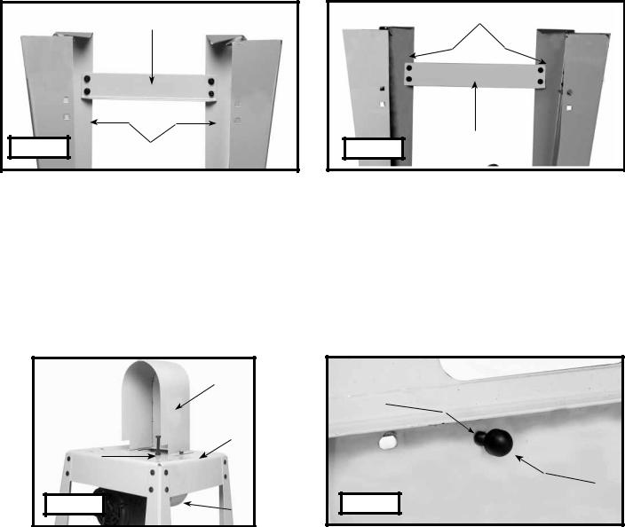
14.Align the four holes in the short brace (A) Fig. 14 with the four holes in the two legs (B).
15.Insert a carriage head bolt (M8x1.25x16mm) through the hole in the stand and the hole the short brace.
16.Thread a flange nut (M8x1.25) on the screw.
NOTE: Loosely tighten the hardware for further adjustment.
17.Repeat this process for the three remaining holes.
18.Attach the remaining short brace to the opposite side of the stand in the same manner.
19.Align the four holes in the long brace (A) Fig. 15 with the four holes in the two legs (B).
20.Insert a carriage head bolt (M8x1.25x16mm) through the hole in the stand and the hole in the long brace.
21.Thread a flange nut (M8x1.25) on the screw.
NOTE: Loosely tighten the hardware for further adjustment.
22.Repeat this process for the three remaining holes.
23.Attach the remaining long brace to the opposite side of the stand in the same manner.
A |
B |
|
Fig. 14 |
B |
A |
Fig. 15 |
24.Turn the stand right side up.
25.Thread a hex nut (M10x1.5) on a hex head screw (M10x1.5x80mm) approximately 1/4".
26.Thread the hex head screw into the hole (A) Fig. 16 in the top of the stand. Place the damping cap (A) Fig. 16A on the threaded end of the screw (C).
27.Confirm that the stand is level.
28.Securely tighten all hardware.
NOTE: Pulley guards (D) and (C) will be attached after the belt has been installed.
|
D |
|
C |
|
B |
A |
|
|
A |
Fig. 16 |
Fig. 16A |
|
C |
13 - English
ATTACHING THE SAW TO THE STAND
 THE BAND SAW IS VERY HEAVY. Use a helper when you attach the saw to the stand.
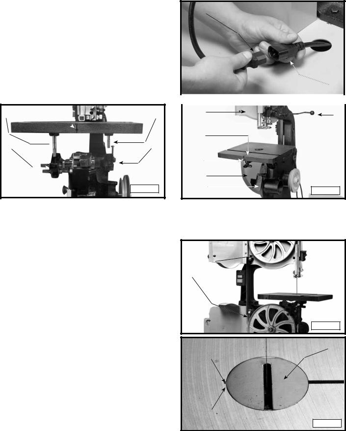
1.Place the band saw on top of the stand as shown in Fig. 17.
NOTE: Confirm that the pulley is on the same side of the stand as the pulley guard.
2.Align the four holes in the saw with the four holes in the top of the stand.
3.Place an M8 lockwasher and a M8 flat washer on a
hex head screw (M8x1.25x40mm). Insert the screw |
A |
|
through one of the holes (A) in the saw and the |
B |
|
stand. |
||
|
4. Thread a hex nut (M8x1.25) on the screw and tighten |
Fig. 17 |
securely. |
5.Repeat this process for the other hole (A).
6.Attach the belt to the saw and motor pulley. See the section "ATTACHING BELT TO SAW AND MOTOR
PULLEY".
7.Repeat STEPS 3 AND 4 for the two remaining holes (B) Fig. 17 (one of which is shown).
ATTACHING THE BELT TO THE SAW AND MOTOR PULLEY
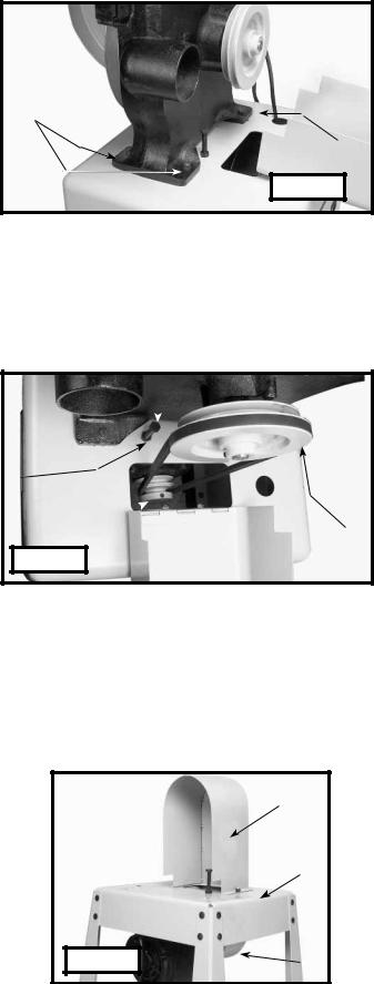
1.Place the belt over the saw pulley (A) Fig. 18.
NOTE: The model 28-276 has a one-step pulley. The model 28-206 has a two-step pulley (Fig. 18).
2.Lift the motor and place the other end of the belt around the motor pulley (B) Fig. 18. The weight of the motor will provide the correct belt tension.
 Operate the machine ONLY with all the guards in place and secure.
3.Check the alignment of the motor and saw pulley.
4.Loosen the four bolts (C) Fig. 12 that hold the motor bracket to the motor mounting plate, and adjust the position of the motor until the motor pulley and saw pulley are aligned.
C 

D
B 

A
Fig. 18 |
5.Tighten the four bolts that were loosened in STEP 4.
6.Turn bolt (C) Fig. 18, clockwise, until the dampening cap contacts the motor.
7.Back the bolt (C) Fig. 18 out approximately 1/4" and tighten the nut (D) against the top of the stand to hold bolt
(C)in place.
NOTE: Do not use the bolt and dampening washer to tension the belt. These two parts prevent the motor from rising excessively when the motor starts.
ATTACHING THE PULLEY GUARDS
NOTE: The illustration in Fig. 18A shows the stand without the band saw for clarity.
1.Insert the two threaded studs on the lower pulley guard (C) Fig 18A through the two holes in the top of the stand (B).
2.Align the two holes in the upper pulley guard (D) Fig. 18A with the two threaded studs on the lower pulley guard (C). Place the upper pulley guard on the studs of the lower pulley guard.
3.Thread a hex flange nut (M8x1.25) on each of the studs and tighten securely.
D
B
A 
Fig. 18A |
C |
14 - English
CONNECTING MOTOR CORD TO SWITCH ASSEMBLY
 Disconnect the machine from the power source!
Insert the motor plug (A) Fig. 18B into the receptacle (B) of the switch-to-motor cord.
ATTACHING THE TABLE TO THE SAW
1.Remove the band saw blade.
2.Align the two table studs (A) Fig. 19 in the bottom of the table with the two holes in the trunnion assemblies (B).
NOTE: Confirm that the slot (C) Fig. 19 is facing toward the front.
3.Place an M13 flat washer on the table stud and thread the table knob on the table stud.
4.Repeat this process for the remaining table stud.
A C 
 A
A
B  B
B
Fig. 19
B
|
|
Fig. 18B |
A |
|
|
|
|
|
|
|
|
|
|
|
|
|
|
|
|
|
|
B |
D |
|
|
|
|
||
|
|
E |
|
|
A |
|
B |
|
C |
Fig. 20 |
|
ATTACHING BLADE TO THE SAW
 Disconnect the machine from the power source!
NOTE: The 14" band saw uses 93-1/2" length blades.
1.Remove the table pin (A) Fig. 20 from the table.
2.Open the two wheel guard doors (B) Fig. 20 and the blade guard door (C).
3.Confirm that the quick tension lever (D) Fig. 20 is positioned to the left of the machine.
NOTE: Install the blade with the teeth pointing down, toward the table.
4.Slide the band saw blade, (teeth facing out), through the slot (E) Fig. 20 in the band saw table.
5.Place the blade around the two wheel assemblies (A) Fig. 21.
6.Replace the table pin (A) Fig. 20.
7.Close the two wheel-guard doors (B) Fig. 20 and the blade guard door (C).
8.Move the quick tension lever (D) Fig. 20 to the right .
9.See the section "OPERATING CONTROLS AND ADJUSTMENTS" to adjust the blade tension and tracking.
TABLE INSERT
Place the table insert (A) Fig. 22 in opening of table.
NOTE: A tab (B) on the insert fits into the notch (C) in table opening.
A 
Fig. 21
A
C 
B 
Fig. 22
15 - English

OPERATION
OPERATIONAL CONTROLS AND ADJUSTMENTS
STARTING AND STOPPING THE SAW
|
|
|
Make sure that the switch is in the |
A |
“OFF” position before plugging cord into outlet. Do |
|
|||
not touch the plug’s metal prongs when unplugging |
|
|||
or plugging in the cord |
|
|||
|
|
|
|
B |
The power switch is located on the left side of the machine. To turn the machine "ON", push the green start button (A) Fig. 23. To turn the machine "OFF", push the red stop button (B).
LOCKING THE SWITCH IN THE "OFF" POSITION
IMPORTANT: When the tool is not in use, the switch should be locked in the "OFF" position to prevent unauthorized use, using a padlock (Fig. 24) with a 3/16" diameter shackle.
 In the event of a power outage (such as a breaker or fuse trip), always move the switch to the “OFF” position until the main power is restored.
Fig. 23
Fig. 24
TILTING THE TABLE
You can tilt the band saw table 45 degrees to the right and 10 degrees to the left.
1.To tilt the table to the right, loosen the two locking knobs (A) Fig. 25, tilt the table to the desired angle as shown on the scale (D) Figs. 25 and 26, and tighten two locking knobs (A).
2.To tilt the table (C) Fig. 26 to the left, loosen the two locking knobs (A) Fig. 25 and tilt the table to the right until you have access to the table stop (A) Fig. 26. Remove the table stop (A) Fig. 26, and tilt the table to the left 10 degrees. Tighten the two locking knobs
(A) Fig. 25.
D
A
Fig. 25 |
|
A |
C |
E |
|
|
D |
|
|
A |
|
|
B |
F |
Fig. 26
16 - English
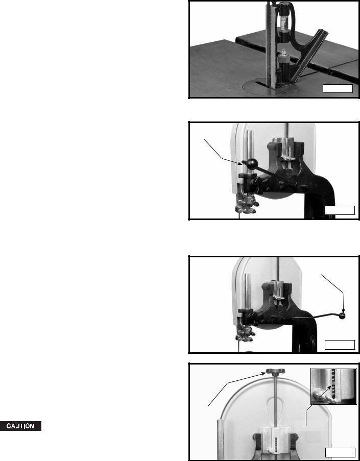
ADJUSTING THE TABLE STOP
This machine is equipped with an adjustable table stop
(A) Fig. 26 that allows the table to be set at 90 degrees to the blade.
Tilt the table (C) Fig. 26 to the left until the table stop
(A) Fig. 26 contacts the table. Place a square on the table against the blade (Fig. 27). If the blade is not 90 degrees to the table surface:
1. |
Tilt the table slightly to the right and tighten the table |
|
|
lock knobs. |
|
2. |
Loosen the locknut (B) Fig. 26 to free the adjusting |
|
|
screw (A) Fig. 26. Turn the adjusting screw (A) right |
|
|
or left to raise or lower the table stop, then tighten |
|
|
the locknut (B). |
|
3. |
Lower the table. Check the angle with the square. |
A |
|
|
4.When the table is 90 degrees to the blade, confirm that the pointer (E) Fig. 26 is set to 0°. If not, loosen the screw (F) Fig. 26 and move the pointer to 0°. Tighten the screw.
ADJUSTING BLADE TENSION
 Disconnect the machine from the power source!
The machine is equipped with a tension handle (A) Fig. |
|
|
28. To apply tension, move the tension handle (A) Fig. 28 |
|
|
toward the back. To release the blade tension, move the |
|
|
tension handle (A) Fig. 29 toward the front. |
|
|
To adjust the blade tension, move the blade tension |
|
|
handle toward the back (Fig. 29). A scale is located |
|
|
on the back of the upper wheel slide bracket. The |
|
|
graduations on the scale indicate the proper tension for |
|
|
various widths of blades. With the blade on the wheels, |
|
|
turn the knob (A) Fig. 30 to raise or lower the wheel until |
|
|
the red fiber washer (B) Fig. 30 is in line with the proper |
|
|
graduation for the size of the blade used. |
|
|
This scale is correct for average work and will not be |
|
|
affected by rebrazing of the saw blade. Use these |
|
|
graduations until you become familiar enough with |
|
|
the operation of the band saw to vary the tension for |
A |
|
different kinds of blades or work. |
||
|
||
Over-straining the blade is a common |
|
|
cause of breakage and/or poor performance. Release |
|
|
the tension when the machine is not in use. |
|
Fig. 27
Fig. 28
A
Fig. 29
B
Fig. 30
17 - English
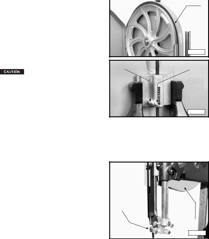
TRACKING THE BLADE
 Disconnect the machine from the power source!
IMPORTANT: Before tracking the blade, confirm that |
A |
|
the blade guides and blade support bearings are clear |
||
|
||
of the blade. |
|
After applying tension to the blade, rotate the wheels |
|
slowly forward by hand and observe the blade’s |
|
movement. The blade (A) Fig. 31 should travel in the |
|
center of the upper tire. If the blade creeps toward the |
|
front edge, loosen the wing nut (B) Fig. 32 and turn the |
|
thumb screw (C) clockwise. This action draws the blade |
|
toward the center of the tire. If the blade creeps toward |
Fig. 31 |
the back edge, turn the thumb screw in the opposite |
|
direction. Adjust the thumb screw (C) Fig. 32 only a |
|
fraction of a turn each time. |
|
B |
C |
Never track the blade while the machine |
|
is running. |
|
After the blade is tracking in the center of the tires, |
|
tighten the wing nut (B) Fig. 32. |
|
|
Fig. 32 |
VERTICAL ADJUSTMENT OF THE UPPER BLADE GUIDE ASSEMBLY
 Disconnect the machine from the power source!
To adjust the blade guides and bearings:
Set the upper blade guide assembly (A) Fig. 33 as close as possible to the top surface of the workpiece. Loosen the lock knob (B) and move the guide assembly (A) to the desired position.
A
B
Fig. 33
18 - English
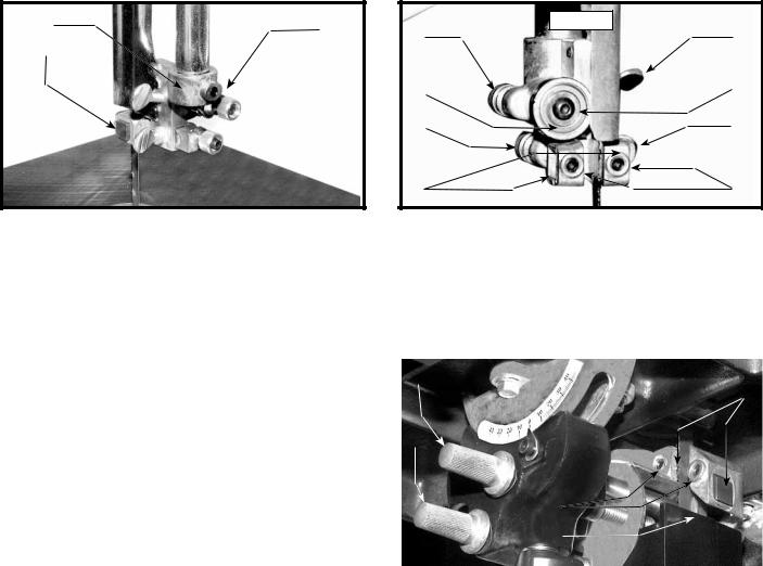
ADJUSTING THE UPPER BLADE GUIDES AND BLADE SUPPORT BEARING
Adjust the upper blade guides and blade support bearings ONLY AFTER the blade has the correct tension and is tracking properly. To adjust:
 Disconnect the machine from the power source!
1.Confirm that the bottom blade guides and support bearings are not touching the blade.
2.Observe the upper blade guide assembly. The blade guides (A) Fig. 34 should be parallel to the blade. To adjust, loosen the screw (B) and rotate the complete guide assembly (C). When the blade guides are parallel with the blade, tighten the screw (B).
3.Adjust the guides (A) Fig. 35 so that the front edge of the guides are just behind the "gullets" of the saw teeth. You can move the complete guide block bracket in or out by loosening the thumb screw (C) and turning the knurled knob (D) Fig. 35. When the guides (A) are set properly, tighten the thumb screw (C).
5.Two set screws (B) Fig. 35 hold the upper blade guides (A) in place. Loosen the set screws (B) to move the guides (A). Place them as close as possible to the side of the blade. (Do not pinch the blade). Tighten the screws (B).
6.The upper blade support bearing (E) Fig. 35 prevents damage to the set in the saw teeth by keeping the blade held forward. Set the support bearing (E) 1/64" behind the blade. Loosen the thumb screw (F) and turn the knurled knob (G) to move the support bearing (E) in or out.
7.Adjust the blade support bearing (E) so that the back edge of the blade overlaps the outside diameter of the ball bearing by about 1/16". The bearing (E) is set on an eccentric. To change the position, remove the screw (H) and bearing (E) Fig. 35. Loosen the thumb screw (F), and back out the knurled knob from the set screw. Remove the hex shaft from the hole, and rotate it to move the eccentric for the bearing.
8.When the blade guide wears so that it cannot be adjusted close to the blade, loosen the screw (B) Fig. 35 and reverse the blade guides (A) Fig. 35.
C |
Fig. 34 |
B |
|
||
|
|
|
A |
|
|
|
Fig. 35 |
G |
F |
E |
H |
|
|
D |
C |
A |
B |
ADJUSTING LOWER BLADE GUIDES AND BLADE SUPPORT BEARING
Adjust the lower blade guides and blade support bearing after the the upper guides and bearing have been adjusted.
 Disconnect the machine from the power source!
1. |
Turn the knurled knob (C) Fig. 36 to adjust the front |
E |
|
|
|
|
edge of the guide blocks (B) Fig. 36 so that they are |
Fig. 36 |
B |
||
|
just behind the "gullets" of the saw teeth. |
|
|
|
|
|
NOTE: The support bearing (D) Fig. 36 should not be |
|
|
|
|
|
touching the back of the blade. |
C |
|
|
|
2. |
Loosen the two screws (A) Fig. 36. Move the guides |
|
|
||
|
|
|
|
||
|
(B) as close as possible to the side of the blade, being |
|
|
|
|
|
careful not to pinch the blade. Tighten the screws (A). |
|
|
|
|
3. |
Turn the other knurled knob (E) to adjust the lower |
|
|
A |
|
|
blade support bearing (D) Fig. 36 so that it is about |
|
|
||
|
1/64" behind the back of the blade. |
|
|
D |
|
|
|
|
|
||
|
|
|
|
|
|
19 - English
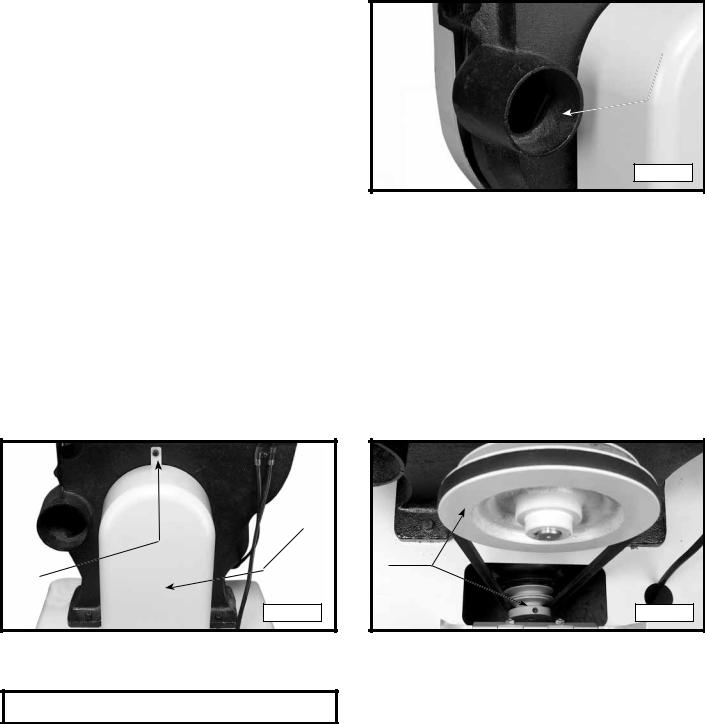
DUST PORT
A dust port (A) Fig. 36A enables you to connect your band saw to a dust collector.
NOTE": The dust port is 4" O.D.
A
Fig. 36A
CHANGING BLADE SPEED FOR MODEL 28-206 ONLY


 Disconnect the machine from the power source!
1.Remove the pulley guard (A) Fig. 37 by removing screw (B).
2.Lift the motor, place the belt on the selected step of the pulleys (A) Fig;. 38, and release the motor.
3.The motor has two speeds: 3300 fpm (good for general work), and 2500 fpm (used for resaw work).
NOTE: The motor will achieve 3300 fpm with the belt placed on the large motor pulley and the small saw pulley. The motor will achieve 2500 fpm with the belt placed on the small motor pulley and the large saw pulley.
A |
|
B |
A |
|
|
Fig. 37 |
Fig. 38 |
MACHINE USE
Before applying power to the machine, make all necessary adjustments and ensure that all guards are in place and are secure. Turn the upper wheel by hand to visually inspect the machine.
Keep the top guide within 1/8" of the workpiece. Do not force the workpiece against the blade. Light pressure will produce a smoother cut and prevent excess friction and heating of the blade. Keep the workpiece moving at a slow and consistent rate.
To prevent twisting of the blade, avoid making sharp corner cuts.
KEEP THE SAW BLADE SHARP.
20 - English
CUTTING CURVES
Turn the stock carefully so that the blade follows without twisting. For very abrupt curves, consider using a narrower blade, or a blade with more set. Another solution to this problem is to make relief cuts (Fig. 39).
When you withdraw the workpiece or change the cut, be careful not to accidentally pull the blade off of the wheels. The preference is to turn the stock and saw out through the waste material.
Fig. 39
TROUBLESHOOTING GUIDE
For assistance with your machine, visit our website at www.deltamachinery.com for a list of service centers or call the DELTA Machinery help line at 1-800-223-7278 (In Canada call 1-800-463-3582).
In spite of how well a band saw is maintained, problems can occur. The following troubleshooting guide will help you solve the more common problems:
Trouble: SAW WILL NOT START.
Probable Cause |
Remedy |
1.Saw not plugged in.
2.Fuse blown or circuit breaker tripped.
3.Cord damaged.
1.Plug in saw.
2.Replace fuse or reset circuit breaker.
3.Have cord replaced.
Trouble: BREAKER KICKS OUT FREQUENTLY. |
|
|
|
Probable Cause |
Remedy |
||
1. |
Extension cord too light or too long. |
1. |
Replace with adequate size cord. |
2. |
Feeding stock too fast. |
2. |
Feed stock more slowly. |
3. |
Blade in poor condition (dull, warped, gummed). |
3. |
Clean or replace blade. |
4. |
Low voltage supply. |
4. |
Contact an electrician. |
Trouble: BAND SAW VIBRATES EXCESSIVELY. |
|
|
|
Probable Cause |
Remedy |
||
1. |
Machine not mounted securely to stand. |
1. |
Tighten all mounting hardware. |
2. |
Stand on uneven surface. |
2. |
Reposition on flat level surface. |
3. |
Worn belt. |
3. |
Replace belt. |
4. |
Pulley not aligned. |
4. |
Adjust pulleys. |
5. |
Motor not fastened securely. |
5. |
Tighten all mounting hardware. |
(continued on next page)
21 - English
Trouble: BAND SAW DOES NOT COME UP TO SPEED. |
|
|
|
Probable Cause |
Remedy |
||
1. |
Low voltage due to improper extension cord size. |
1. |
Replace with adequate size cord. |
2. |
Low voltage. |
2. |
Contact an electrician. |
Trouble: BLADES BREAK.
Probable Cause
1.Blade not tensioned properly.
2.Blade guides improperly adjusted.
3.Blade support bearing improperly adjusted.
4.Blade wheel tracking adjustment improperly set.
5.Bad weld on blade.
6.Worn tires.
7.Forcing wide blade around short radius.
8.Dull blade or insufficient set.
9.Upper blade guide set too high.
10.Continuous running of machine when not actually cutting.
Trouble: BLADE WILL NOT TRACK.
Probable Cause
1.Blade too loose
2.Upper wheel not properly adjusted.
3.Improperly adjusted blade support bearing.
Remedy
1.Adjust blade tension.
2.Check and adjust blade guides.
3.Adjust blade support bearing.
4.Check and adjust blade tracking.
5.Replace the blade.
6.Replace tires.
7.Change to a narrower blade.
8.Replace blade.
9.Set upper blade guide within 1/8" of workpiece.
10.Turn off machine when not performing cutting operation.
Remedy
1.Adjust tension
2.Adjust upper wheel.
3.Adjust blade support bearing.
Trouble: CUT DOES NOT AGREE WITH SETTING ON THE TILT SCALE.
Probable Cause |
Remedy |
||
1. |
Pointer out of adjustment |
1. |
Adjust pointer. |
Trouble: BLADE WILL NOT STAY ON WHEEL. |
|
|
|
Probable Cause |
Remedy |
||
1. |
Blade not tensioned properly. |
1. |
Adjust blade tension. |
2. |
Blade guides improperly adjusted. |
2. |
Check and adjust blade guides. |
3. |
Blade support bearing improperly adjusted. |
3. |
Adjust blade support bearing. |
4. |
Blade wheel not tracking properly. |
4. |
Check and adjust blade tracking. |
5. |
Bad weld on blade. |
5. |
Replace the blade. |
6. |
Worn tires. |
6. |
Replace tires. |
Trouble: BAND SAW MAKES UNSATISFACTORY CUTS. |
|
|
|
Probable Cause |
Remedy |
||
1. |
Blade not tensioned properly. |
1. |
Adjust blade tension. |
2. |
Blade guides improperly adjusted. |
2. |
Check and adjust blade guides. |
3. |
Blade support bearing improperly set. |
3. |
Adjust blade support bearing. |
4. |
Blade wheel not tracking properly. |
4. |
Check and adjust blade tracking. |
5. |
Bad weld on blade. |
5. |
Replace the blade. |
6. |
Worn tires. |
6. |
Replace tires. |
7. |
Incorrect blade for work being done. |
7. |
Change the blade. |
8. |
Dull blade or insufficient set. |
8. |
Replace blade. |
9. |
Upper blade guide set too high. |
9. |
Set upper blade guide within 1/8" of work piece. |
22 - English
 Loading...