


 Loading...


Preface
Thank you for choosing DELTA’s high-performance VFD-S Series. The VFD-S Series is manufactured with high-quality components and materials and incorporate the latest microprocessor technology available.
This manual is to be used for the installation, parameter setting, troubleshooting, and daily maintenance of the AC motor drive. To guarantee safe operation of the equipment, read the following safety guidelines before connecting power to the AC motor drive. Keep this operating manual at hand and distribute to all users for reference.
To ensure the safety of operators and equipment, only qualified personnel familiar with AC motor drive are to do installation, start-up and maintenance. Always read this manual thoroughly before using VFD-S series AC Motor Drive, especially the WARNING, DANGER and CAUTION notes.
Failure to comply may result in personal injury and equipment damage. If you have any questions, please contact your dealer.
PLEASE READ PRIOR TO INSTALLATION FOR SAFETY.
 DANGER!
1.AC input power must be disconnected before any wiring to the AC motor drive is made.
2.A charge may still remain in the DC-link capacitors with hazardous voltages, even if the power has been turned off. To prevent personal injury, please ensure that power has been turned off before opening the AC motor drive and wait ten minutes for the capacitors to discharge to safe voltage levels.
3.Never reassemble internal components or wiring.
4.The AC motor drive may be destroyed beyond repair if incorrect cables are connected to the input/output terminals. Never connect the AC motor drive output terminals U/T1, V/T2, and W/T3 directly to the AC mains circuit power supply.
5.Ground the VFD-S using the ground terminal. The grounding method must comply with the laws of the country where the AC motor drive is to be installed. Refer to the Basic Wiring Diagram.
6.VFD-S series is used only to control variable speed of 3-phase induction motors, NOT for 1- phase motors or other purpose.
7.VFD-S series shall NOT be used for life support equipment or any life safety situation.

 WARNING!
1.DO NOT use Hi-pot test for internal components. The semi-conductor used in the AC motor drive is easily damaged by high-pressure.
2.There are highly sensitive MOS components on the printed circuit boards. These components are especially sensitive to static electricity. To prevent damage to these components, do not touch these components or the circuit boards with metal objects or your bare hands.
3.Only qualified personnel are allowed to install, wire and maintain AC motor drive.
 CAUTION!
1.Some parameter settings will cause the motor to run immediately after applying power.
2.DO NOT install the AC motor drive in a place subjected to high temperature, direct sunlight, high humidity, excessive vibration, corrosive gases or liquids, or airborne dust or metallic particles.
3.Only use AC motor drives within specification. Failure to comply may result in fire, explosion or electric shock.
4.To prevent personal injury, please keep children and unqualified people away from the equipment.
5.When the motor cable between the AC motor drive and motor is too long, the layer insulation of the motor may be damaged. Please use a frequency inverter duty motor or add an AC output reactor to prevent damage to the motor. Refer to appendix B Reactor for details.
6.The rated voltage for the AC motor drive must be ≤ 240V for 230V models (≤ 120V for 115V models, ≤ 480V for 460V models) and the mains supply current capacity must be ≤ 5000A RMS (≤10000A RMS for the ≥ 40hp (30kW) models).

Table of Contents
Preface .............................................................................................................. |
i |
|
Table of Contents ........................................................................................... |
iii |
|
Chapter 1 Introduction................................................................................. |
1-1 |
|
1.1 |
Receiving and Inspection.................................................................... |
1-1 |
1.1.1 Nameplate Information................................................................ |
1-1 |
|
1.1.2 Model Explanation ...................................................................... |
1-1 |
|
1.1.3 Series Number Explanation ........................................................ |
1-2 |
|
1.1.4 Drive Frames .............................................................................. |
1-2 |
|
1.2 |
Appearances....................................................................................... |
1-2 |
1.3 |
Installation Steps ................................................................................ |
1-3 |
1.4 |
Storage ............................................................................................... |
1-4 |
Chapter 2 Installation and Wiring ............................................................... |
2-1 |
|
2.1 |
Ambient Conditions............................................................................. |
2-1 |
2.2 |
Installation........................................................................................... |
2-1 |
2.3 |
Dimensions......................................................................................... |
2-3 |
2.4 |
Wiring ............................................................................................... |
2-16 |
2.4.1 Basic Wiring.............................................................................. |
2-17 |
|
2.4.2 External Wiring.......................................................................... |
2-22 |
|
2.4.3 Main Terminals Connections .................................................... |
2-23 |
|
2.4.4 Control Terminals...................................................................... |
2-25 |
|
2.4.5 Main Circuit Terminals .............................................................. |
2-28 |
|
Chapter 3 Start Up........................................................................................ |
3-1 |
|
3.1 |
Preparations before Start-up............................................................... |
3-1 |
3.2 |
Operation Method ............................................................................... |
3-2 |
3.3 |
Trial Run ............................................................................................. |
3-2 |
Chapter 4 Digital Keypad Operation ........................................................... |
4-1 |
|
4.1 |
Description of the Digital Keypad........................................................ |
4-1 |
4.2 |
Explanation of LED Indicators............................................................. |
4-1 |
4.3 |
Explanations of Display Messages ..................................................... |
4-1 |
4.4 |
How to Operate the Digital Keypad..................................................... |
4-3 |
Chapter 5 Parameters .................................................................................. |
5-1 |
|
5.1 |
Summary of Parameter Settings......................................................... |
5-2 |
Group 0 User Parameters.................................................................... |
5-2 |
|
Group 1 Basic Parameters................................................................... |
5-2 |
|
Group 2 Operation Method Parameters............................................... |
5-3 |
|
Group 3 Output Function Parameters .................................................. |
5-5 |
|
Group 4 Input Function Parameters..................................................... |
5-5 |
|
Group 5 Multi-Step Speed and PLC Parameters ................................. |
5-7 |
|
Group 6 Protection Parameters ........................................................... |
5-7 |
|
Group 7 Motor Parameters .................................................................. |
5-9 |
|
Group 8 Special Parameters................................................................ |
5-9 |
|
Group 9 Communication Parameters................................................. |
5-10 |
|
Group A PID Parameters ................................................................... |
5-10 |
|
5.2 |
Parameter Settings for Applications.................................................. |
5-12 |
5.3 |
Description of Parameter Settings .................................................... |
5-17 |
Group 0: User Parameters................................................................. |
5-17 |
|
Group 1: Basic Parameters................................................................ |
5-22 |
|
Group 2: Operation Method Parameters............................................ |
5-27 |
|
Group 3: Output Function Parameters ............................................... |
5-31 |
|
Group 4: Input Function Parameters................................................. |
5-35 |
|
Group 5: Multi-step Speeds and PLC Parameters............................. |
5-47 |
|
Group 6: Protection Parameters ....................................................... |
5-52 |
|
Group 7: Motor Parameters .............................................................. |
5-57 |
|
Group 8: Special Parameters............................................................. |
5-58 |
|
Group 9: Communication Parameters............................................... |
5-62 |
|
Group A: PID Control ......................................................................... |
5-75 |
|
Chapter 6 Fault Code Information............................................................... |
6-1 |
|
6.1 |
Common Problems and Solutions ...................................................... |
6-1 |
6.2 |
Reset .................................................................................................. |
6-4 |
Chapter 7 Troubleshooting.......................................................................... |
7-1 |
|
7.1 |
Over Current (OC) .............................................................................. |
7-1 |
7.2 |
Ground Fault....................................................................................... |
7-2 |
7.3 |
Over Voltage (OV) .............................................................................. |
7-2 |
7.4 |
Low Voltage (Lv)................................................................................. |
7-3 |
7.5 |
Over Heat (OH)................................................................................... |
7-4 |
7.6 |
Overload ............................................................................................. |
7-4 |
7.7 |
Keypad Display is Abnormal ............................................................... |
7-5 |
7.8 |
Phase Loss (PHL)............................................................................... |
7-5 |
7.9 |
Motor cannot Run ............................................................................... |
7-6 |
7.10 Motor Speed cannot be Changed ..................................................... |
7-7 |
|
7.11 Motor Stalls during Acceleration ....................................................... |
7-8 |
|
7.12 The Motor does not Run as Expected .............................................. |
7-8 |
|
7.13 Electromagnetic/Induction Noise ...................................................... |
7-9 |
|
7.14 Environmental Condition................................................................... |
7-9 |
|
7.15 Affecting Other Machines ............................................................... |
7-10 |
|
Chapter 8 Maintenance and Inspections.................................................... |
8-1 |
|
Appendix A Specifications ......................................................................... |
A-1 |
|
Appendix B Accessories ............................................................................ |
B-1 |
|
B.1 |
All Brake Resistors & Brake Units Used in AC Motor Drives.............. |
B-1 |
B.1.1 Dimensions and Weights for Brake resistors.............................. |
B-3 |
|
B.2 |
EMI Filters .......................................................................................... |
B-4 |
B.2.1 Dimensions................................................................................. |
B-7 |
|
B.3 |
AC Reactor....................................................................................... |
B-11 |
B.3.1 AC Input Reactor Recommended Value................................... |
B-11 |
|
B.3.2 AC Output Reactor Recommended Value................................ |
B-11 |
|
B.3.3 Applications for AC Reactor ..................................................... |
B-12 |
|
B.4 DC Choke Recommended Values.................................................... |
B-14 |
|
B.5 |
Zero Phase Reactor (RF220X00A) .................................................. |
B-15 |
B.6 |
Din Rail-DR01 .................................................................................. |
B-16 |
B.7 |
Remote Controller RC-01................................................................. |
B-17 |
B.8 |
Conduit Bracket (BK-S) .................................................................... |
B-18 |
B.9 |
Non-fuse Circuit Breaker Chart ........................................................ |
B-19 |
Appendix C How to Select the Right AC Motor Drive............................... |
C-1 |
|
C.1 Capacity Formulas ............................................................................. |
C-2 |
|
C.2 General Precautions .......................................................................... |
C-4 |
|
C.3 How to Choose a Suitable Motor........................................................ |
C-5 |
|

Chapter 1 Introduction
1.1 Receiving and Inspection
This VFD-S AC motor drive has gone through rigorous quality control tests at the factory before shipment. After receiving the AC motor drive, please check for the following:
Check to make sure that the package includes an AC motor drive, the User Manual/Quick Start and CD, dust covers and rubber bushings.
Inspect the unit to assure it was not damaged during shipment.
Make sure that the part number indicated on the nameplate corresponds with the part number of your order.
1.1.1 Nameplate Information
Example for 1HP/0.75kW 3-phase 230V AC motor drive
AC Drive Model |
|
|
|
MODEL |
|
: VFD007S23A |
|
|
|||||||||||||||||||||||||
|
|
|
|
||||||||||||||||||||||||||||||
Input Spec. |
|
|
|
INPUT |
|
: 3PH 200-240V 50/60Hz 5.1A |
|||||||||||||||||||||||||||
|
|
||||||||||||||||||||||||||||||||
Output Spec. |
|
|
|
OUTPUT : 3PH 0-240V 4.2A 1.6kVA 0.75kW/1HP |
|||||||||||||||||||||||||||||
|
|
||||||||||||||||||||||||||||||||
Output Frequency Range |
|
|
|
Frequency Range : 1-400Hz |
|
|
|||||||||||||||||||||||||||
|
|
|
|
||||||||||||||||||||||||||||||
Serial Number & Bar Code |
|
|
|
|
|
|
|
|
|
|
|
|
|
|
|
|
|
|
|
|
|
|
|
|
|
|
|
|
|
|
|
||
|
|
|
|
|
|
|
|
|
|
|
|
|
|
|
|
|
|
|
|
|
|
|
|
|
|
|
|
|
|
|
|
||
|
|
|
|
|
|
|
|
|
|
|
|
007S23A0T7010001 |
|
|
|||||||||||||||||||
|
|
|
|
|
|
|
|
|
|
|
|
|
|||||||||||||||||||||
|
|
|
|
|
|
|
|
|
|
|
|
|
|
|
|
|
|
|
|
|
|
|
|
|
|
|
|
|
|
|
|
|
|
|
|
|
|
|
|
DELTA ELECTRONICS INC. |
MADE IN XXXXX |
||||||||||||||||||||||||||
|
|
|
|
|
|
|
|
|
|
|
|
|
|
|
|
|
|
|
|
|
|
|
|
|
|
|
|
|
|
|
|
|
|
1.1.2 Model Explanation
VFD 007 S 23 A Version Type
Input Voltage 11:Single phase 115V 21:Single phase 230V 23:Three phase 230V
43:Three phase 460V
S Series
Applicable motor capacity
002: 0.25HP(0.2kW) 004: 0.5HP(0.4kW) 007: 1 HP(0.7kW)
Series Name |
022: 3 HP(2.2kW) |
Revision August 2008, SE09, SW V2.61 |
1-1 |
Chapter 1 Introduction|VFD-S Series
1.1.3Series Number Explanation
007S23A 0T 6 01 


Production number Production week Production year 2006 Production factory
(Taoyuan)
230V 3-phase 1HP(0.75kW)
Model
If the nameplate information does not correspond to your purchase order or if there are any problems, please contact your distributor.
1.1.4 Drive Frames
Frame |
Power range |
Models |
|
|
0.25-2hp |
VFD002S11A/11B/21A/21B/21E/23A, |
|
S1 |
VFD004S11A/11B/21A/21B/21E/23A/43A/43B/43E, |
||
(0.2-1.5kW) |
|||
|
VFD007S21A/21B/21E/23A/43A/43B/43E, VFD015S23D |
||
|
|
||
S2 |
1-5hp |
VFD007S11A/11B, VFD015S21D/21E/21U/43D/43E/43U, |
|
(0.75-3.7kW) |
VFD022S21D/21E/21U/23D/43D/43E/43U |
||
|
Please refer to Chapter 2.3 for exact dimensions.
1.2 Appearances
VFD002S11A/11B/21A/21B/23A, |
Frame S1: VFD002S21E, VFD004S21E, |
VFD004S11A/11B/21A/21B/23A/43A/43B/43E, |
VFD007S21E, VFD015S23D, |
VFD007S21A/21B/23A/43A/43B/43E, |
Frame S2: VFD007S11A/11B, |
|
VFD015S21D/21E/21U/43D/43E/43U, |
|
VFD022S21D/21E/21U/23D/43D/43E/43U |
1-2 |
Revision August 2008, SE09, SW V2.61 |
Chapter 1 Introduction|VFD-S Series
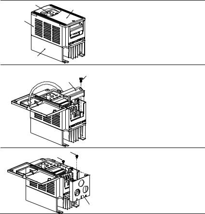
1.3 Installation Steps
KNOB
COVER
CASE
HEAT SINK
SCREW
DIVISION
PLATE
Installation Steps
1. Remove front cover screw and open.
2. Remove Division Plate. If using optional conduit bracket, please refer to next page.
3. Connect AC Input Power and motor leads. Never connect the AC drive output terminals U/T1, V/T2, W/T3 to main AC Input power.
4. Reinstall Division Plate.
SCREW
SCREW
For Optional Conduit Bracket:
Make sure to fasten both screws on conduit bracket as shown in the drawing for safety grounding purpose. Bring all the wires out through the conduit bracket.
Screw Torque: 5 to 6 kgf-cm (4.3 to 5.2 in-lbf)
CONDUIT
BRACKET
Revision August 2008, SE09, SW V2.61 |
1-3 |
Chapter 1 Introduction|VFD-S Series
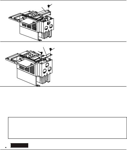
SCREW
DIVISION
PLATE
Reinstall Division Plate.
Screw Torque: 5 to 6 kgf-cm (4.3 to 5.2 in-lbf)
CONDUIT
BRACKET SCREW
SCREW
Install Conduit Bracket cover and tighten screws.
1.4 Storage
The AC motor drive should be kept in the shipping carton or crate before installation. In order to retain the warranty coverage, the AC motor drive should be stored properly when it is not to be used for an extended period of time. Storage conditions are:
Store in a clean and dry location free from direct sunlight or corrosive fumes. Store within an ambient temperature range of -20 °C to +60 °C.
Store within a relative humidity range of 0% to 90% and non-condensing environment. Store within an air pressure range of 86kPa to 106kPa.
 CAUTION!
1.DO NOT store in an area with rapid changes in temperature. It may cause condensation and frost.
2.DO NOT place on the ground directly. It should be stored properly. Moreover, if the surrounding environment is humid, you should put exsiccator in the package.
1-4 |
Revision August 2008, SE09, SW V2.61 |
Chapter 1 Introduction|VFD-S Series
3.If the AC motor drive is stored for more than 3 months, the temperature should not be higher than 30 °C. Storage longer than one year is not recommended, it could result in the degradation of the electrolytic capacitors.
4.When the AC motor drive is not used for a long time after installation on building sites or places with humidity and dust, it’s best to move the AC motor drive to an environment as stated above.
Revision August 2008, SE09, SW V2.61 |
1-5 |
Chapter 1 Introduction|VFD-S Series
This page intentionally left blank.
1-6 |
Revision August 2008, SE09, SW V2.61 |

Chapter 2 Installation and Wiring
2.1 Ambient Conditions
Install the AC motor drive in an environment with the following conditions:
Operation |
Air Temperature: |
-10 ~ +40°C (14 ~ 104°F), Non-condensing |
|
|
|
and not frozen |
|
|
Relative Humidity: |
<90%, no condensation allowed |
|
|
Atmosphere pressure: |
86 |
~ 106 kPa |
|
Installation Site Altitude: |
<1000m |
|
|
Vibration: |
<20Hz: 9.80 m/s2 (1G) max |
|
|
|
20 |
~ 50Hz: 5.88 m/s2 (0.6G) max |
Storage |
Temperature: |
-20°C ~ +60°C (-4°F ~ 140°F) |
|
Transportation |
Relative Humidity: |
<90%, no condensation allowed |
|
|
Atmosphere pressure: |
86 |
~ 106 kPa |
|
Vibration: |
<20Hz: 9.80 m/s2 (1G) max |
|
|
|
20 |
~ 50Hz: 5.88 m/s2 (0.6G) max |
Pollution Degree |
2: good for a factory type environment. |
||
 CAUTION!
1.Operating, storing or transporting the AC motor drive outside these conditions may cause damage to the AC motor drive.
2.Failure to observe these precautions may void the warranty!
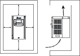
2.2 Installation
1.Mount the AC motor drive vertically on a flat vertical surface by using bolts or screws. Other directions are not allowed.
2.The AC motor drive will generate heat during operation. Allow sufficient space around the unit for heat dissipation.
3.The heat sink temperature may rise to 90°C when running. The material on which the AC motor drive is mounted must be noncombustible and be able to withstand this high temperature.
4.When the AC motor drive is installed in a confined space (e.g. cabinet), the surrounding temperature must be within 10 ~ 40°C with good ventilation. DO NOT install the AC motor drive in a space with bad ventilation.
Revision August 2008, SE09, SW V2.61 |
2-1 |
Chapter 2 Installation and Wiring|VFD-S Series
5.When installing multiple AC motor drives in the same cabinet, they should be adjacent in a row with enough space. When installing one AC motor drive below another one, use a metal separation barrier between the AC motor drives to prevent mutual heating. Refer to figure below for details.
6.Prevent fiber particles, scraps of paper, saw dust, metal particles, etc. from adhering to the heatsink.
Mounting Clearances
150mm |
|
(6inch) |
Air Flow |
50mm (2inch) |
|
(2inch) |
50mm |
150mm |
|
(6inch) |
|
2-2 |
Revision August 2008, SE09, SW V2.61 |
Chapter 2 Installation and Wiring|VFD-S Series
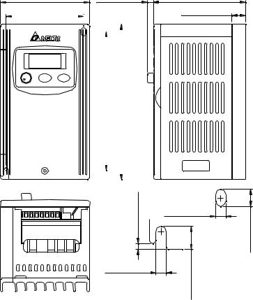
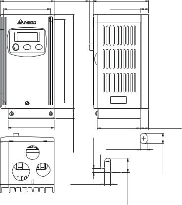
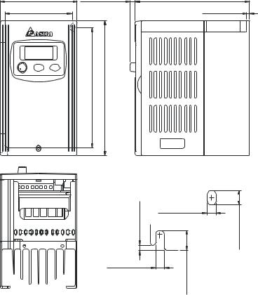
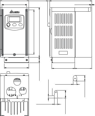
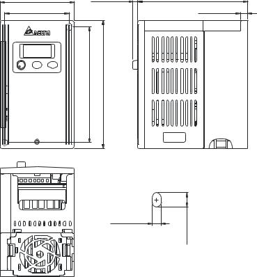
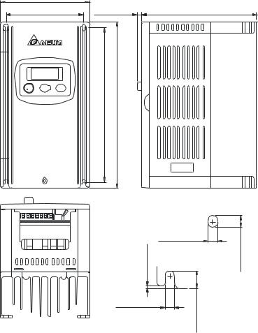
2.3 Dimensions
(Dimensions are in millimeter and [inch])
Frame S1: VFD002S11A, VFD002S21A, VFD002S23A
85.0 [3.35] |
5.8 [0.23] |
88.0 [3.47] |
|||
74.0 [2.92] |
|
|
|
|
13.0 [0.51] |
|
|
|
|
|
|
|
|
|
|
|
|
|
|
|
132.2[5.21] |
|
148.0[5.83] |
|
|
|
|
|
|
|||
|
|
|
|
|
|
|
|
|
|
|
|
|
|
|
|
|
|
|
|
|
|
|
|
|
|
|
|
[0.12] |
5.0 [0.20] |
|
3.0 |
[0.44]11.1 |
|
5.0 [0.20] |
||
|
8.1 [0.32]
Revision August 2008, SE09, SW V2.61 |
2-3 |
Chapter 2 Installation and Wiring|VFD-S Series
Frame S1: VFD002S11B, VFD002S21B
85 .0 [3 .3 5] |
5. 8 [0. 23 ] |
88 .0 [3 .4 7] |
74 .0 [2 .9 2] |
|
13 .0 [0 .5 1] |
[5.21] |
[5.83] |
2.2 |
8.0 |
13 |
14 |
73 .0 [2 .8 8]
16.0[0.63] |
[0.12] |
|
3.0 |
5. 0 [0. 20 ]
67 .8 [2 .6 7] |
13 .0 [0 .5 1] |
5. 0 [0. 20 ] |
|
|
[0.32] |
|
8.1 |
11.1[0.44] |
|
2-4 |
Revision August 2008, SE09, SW V2.61 |
Chapter 2 Installation and Wiring|VFD-S Series
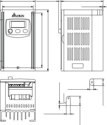
Frame S1: VFD004S11A, VFD004S21A, VFD004S23A
85 .0 |
[3 .3 5] |
5. 8 [0. 23 ] |
74 .0 |
[2 .9 2] |
|
[5.21] |
[5.83] |
32.2 |
48.0 |
1 |
1 |
3.0 [ 0.12]
5. 0 [0. 20 ]
10 2. 0 [ 4. 02]
2. 8 [0. 11 ]
5. 0 [0. 20 ]
8.1 [0.32]
11.1 [0.44]
Revision August 2008, SE09, SW V2.61 |
2-5 |
Chapter 2 Installation and Wiring|VFD-S Series
Frame S1: VFD004S11B, VFD004S21B
85 .0 [3 .3 5] |
5. 8 [0. 23 ] |
10 2. 0 [ 4. 02] |
|
74 .0 [2 .9 2] |
|
|
2. 8 [0. 11 ] |
|
|
|
|
[5.21] |
[5.83] |
132.2 |
148.0 |
73 .0 [2 .8 8]
[0.63] |
|
6.0 |
.12] |
1 |
[0 |
|
3.0 |
5. 0 [0. 20 ]
67 |
.8 |
[2 .6 7] |
27 .0 [1 .0 6] |
5 |
. 0 |
[0. 20 ] |
|
|
|
|
8.1[0.32] |
|
|
[0.44] |
|
|
|
11.1 |
|
2-6 |
Revision August 2008, SE09, SW V2.61 |
Chapter 2 Installation and Wiring|VFD-S Series
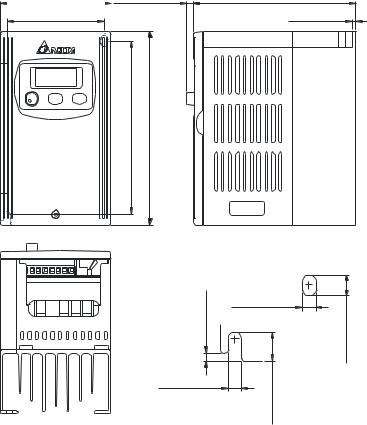
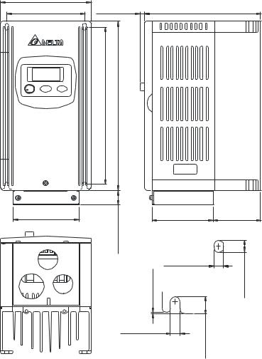
Frame S1: VFD007S21A, VFD007S23A
85 .0 [3 .3 5] |
|
5. 8 [0. 23 ] |
74 .0 [2 .9 2] |
|
|
|
|
|
2.2[5.21] |
8.0[5.83] |
13 |
14 |
3.0 [0 .12]
5. 0 [0. 20 ]
12 4. 0 [ 4. 89]
2. 8 [0. 11 ]
5. 0 [0. 20 ]
8.1 [ 0.32]
1 1.1 [ 0.44]
Revision August 2008, SE09, SW V2.61 |
2-7 |
Chapter 2 Installation and Wiring|VFD-S Series
Frame S1: VFD007S21B
85 .0 |
[3 .3 5] |
5. 8 [0. 23 ] |
12 4. 0 [ 4. 89] |
74 .0 |
[2 .9 2] |
|
2. 8 [0. 11 ] |
[5.21] |
[5.83] |
132.2 |
148.0 |
73 .0 [2 .8 8]
[0.63] |
|
16.0 |
2] |
|
3.0[0.1 |
5. 0 [0. 20 ]
67 .8 [2 .6 7] |
50 .0 [1 .9 7] |
5. 0 [0. 20 ]
|
[0.32] |
.44] |
8.1 |
11.1[0 |
|
2-8 |
Revision August 2008, SE09, SW V2.61 |
Chapter 2 Installation and Wiring|VFD-S Series
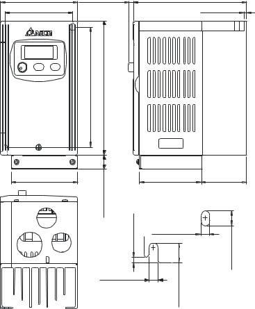
Frame S1: VFD004S43A, VFD004S43E, VFD007S43A, VFD007S43E
85 .0 |
[3 .3 5] |
5. 8 [0. 23 ] |
74 .0 |
[2 .9 2] |
|
13 2.2 [ 5.21] 14 8.0 [ 5.83]
3.0 [0 .12]
5. 0 [0. 20 ]
12 6. 0 [ 4. 96]
3. 0 [0. 12 ]
5. 0 [0. 20 ]
8.1 [0.32]
1 1.1 [ 0.44]
Revision August 2008, SE09, SW V2.61 |
2-9 |
Chapter 2 Installation and Wiring|VFD-S Series
Frame S1: VFD004S43B, VFD007S43B
85 .0 |
[3 .3 5] |
5. 8 [0. 23 ] |
12 6. 0 [ 4. 96] |
74 .0 |
[2 .9 2] |
|
3. 0 [0. 12 ] |
[5.21] |
[5.83] |
32.2 |
48.0 |
1 |
1 |
73 .0 [2 .8 8]
[0.63] |
|
16.0 |
2] |
|
3.0[0.1 |
5. 0 [0. 20 ]
67 .8 [2 .6 7] |
51 .0 [2 .0 1] |
5. 0 [0. 20 ] |
|
|
8.1[0.32] |
11.1[0.44] |
|
2-10 |
Revision August 2008, SE09, SW V2.61 |
Chapter 2 Installation and Wiring|VFD-S Series
Frame S1: VFD002S21E, VFD004S21E, VFD007S21E, VFD015S23D
85 .0 |
[3 .3 5] |
5. 8 [ 0. 23 ] |
12 7. 0 [ 5. 00] |
74 .0 |
[2 .9 2] |
|
8. 5 [ 0. 33 ] |
13 3.7 [ 5.27] 14 8.0 [ 5.83]
5. 0 [ 0. 20 ]
8.3 [ 0.33]
Revision August 2008, SE09, SW V2.61 |
2-11 |
Chapter 2 Installation and Wiring|VFD-S Series
Frame S2: VFD007S11A
10 0. 0 [ 3. 94] |
|
86 .5 [3 .4 1] |
5. 4 [0. 21 ] |
[6.81] |
[7.33] |
173.0 |
186.0 |
1 .0 [0 .04]
5. 5 [0. 22 ]
12 9. 0 [ 5. 08]
5. 5 [0. 22 ]
6.5 [ 0.26]
9 .5 [0 .38]
2-12 |
Revision August 2008, SE09, SW V2.61 |
Frame S2: VFD007S11B
10 0. 0 [ 3. 94]
86 .5 [3 .4 1]
73 .0 [2 .8 8]
Chapter 2 Installation and Wiring|VFD-S Series
5. 4 [0. 21 ] |
12 9. 0 [ 5. 08] |
[6.82] |
[7.33] |
173.0 |
186.0 |
16.0[0.63] |
67 .8 [2 .6 7] |
53 .5 [2 .11] |
|
|
|
|
5. 5 [0. 22 ] |
] |
|
.04] |
[0.26 |
|
.0[0 |
6.5 |
|
1 |
|
|
5. 5 [0. 22 ] |
|
|
9.5[0.38] |
|
Revision August 2008, SE09, SW V2.61 |
2-13 |
Chapter 2 Installation and Wiring|VFD-S Series
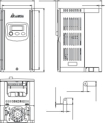
Frame S2: VFD015S21D, VFD015S21E, VFD015S43D, VFD015S43E, VFD022S21D, VFD022S21E, VFD022S23D, VFD022S43D, VFD022S43E
10 0. 0 [ 3. 94] |
5. 4 [0. 21 ] |
86 .5 [3 .4 1] |
|
17 3.0 [ 6.82] 18 6.0 [ 7.33]
1.0 [0.04]
5. 5 [0. 22 ]
12 9. 3 [ 5. 09]
8. 5 [0. 33 ]
5. 5 [0. 22 ] |
] |
|
[0.26 |
|
6.5 |
9.5[0.37] |
|
2-14 |
Revision August 2008, SE09, SW V2.61 |
Chapter 2 Installation and Wiring|VFD-S Series
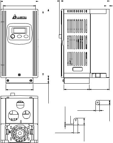
Frame S2: VFD015S21U, VFD015S43U, VFD022S21U, VFD022S43U
100.0 [3.94] |
|
5.4 [0.21] |
|
|
129.3 [5.09] |
|
|
|
||||
|
|
|
|
|
|
|
|
|
|
|
|
|
|
|
|
|
|
|
|
|
|
|
|
|
|
86.5 [3.41] |
|
|
|
|
|
|
8.5 |
[0.33] |
|
|
||
|
|
|
|
|
|
|
|
|
|
|
|
|
|
173.0 [6.82] |
|
|
186.0 [7.33] |
|
|
|||
|
|
|
|
|
|
|
|
|
|
|
|
|
|
|
73.0 [2.88] |
67.8 [2.67] |
53.9 [2.12] |
|
16.0 [0.63] |
|
1.0 [0.04] |
5.5 [0.22] |
|
|
5.5 [0.22] |
37][0. |
|
|
|
9.5 |
6.5 [0.26]
Revision August 2008, SE09, SW V2.61 |
2-15 |
Loading...