


SC1430
Table of contents
 Loading...
Dell™ PowerEdge™
SC1430 Systems
Hardware Owner’s Manual
www.dell.com | support.dell.com

Notes, Notices, and Cautions
NOTE: A NOTE indicates important information that helps you make better use of your computer.
NOTICE: A NOTICE indicates either potential damage to hardware or loss of data and tells you how to avoid the
problem.
CAUTION: A CAUTION indicates a potential for property damage, personal injury, or death.
____________________
Information in this document is subject to change without notice.
© 2006 Dell Inc. All rights reserved.
Reproduction in any manner whatsoever without the written permission of Dell Inc. is strictly forbidden.
Trademarks used in this text: Dell, the DELL logo, Inspiron, Dell Precision, Dimension, OptiPlex, Latitude, P owerEdge, P owerV ault, P owerApp,
PowerConnect, and XPS are trademarks of Dell Inc.; Intel is a registered trademark of Intel Corporation; Microsoft and Windows are registered
trademarks of Microsoft Corporation; EMC is a registered trademark of EMC Corporation.
Other trademarks and trade names may be used in this document to refer to either the entities claiming the marks and names or their products.
Dell Inc. disclaims any proprietary interest in trademarks and trade names other than its own.
Model EMS01
June 2006 P/N WH819 Rev. A00

Contents
1 About Your System. . . . . . . . . . . . . . . . . . . . . . . . . . . . . 9
Other Information You May Need . . . . . . . . . . . . . . . . . . . . . . . . . 9
Accessing System Features During Startup
Front-Panel Features and Indicators
Back-Panel Features and Indicators
Connecting External Devices
NIC Indicator Codes
Diagnostics Indicator Codes
System Messages
Warning Messages
Diagnostics Messages
Alert Messages
. . . . . . . . . . . . . . . . . . . . . . . . . . . . . . . . 17
. . . . . . . . . . . . . . . . . . . . . . . . . . . . . . . 25
. . . . . . . . . . . . . . . . . . . . . . . . . . . . . . 25
. . . . . . . . . . . . . . . . . . . . . . . . . . . . . . . . . 25
. . . . . . . . . . . . . . . . . . . . . . . . 13
. . . . . . . . . . . . . . . . . . . . . . . . . . . . 14
. . . . . . . . . . . . . . . . . . . . . . . . . . . 15
. . . . . . . . . . . . . . . . . . . 10
. . . . . . . . . . . . . . . . . . . . . . 11
. . . . . . . . . . . . . . . . . . . . . . 13
2 Using the System Setup Program . . . . . . . . . . . . . . . . . . 27
Entering the System Setup Program . . . . . . . . . . . . . . . . . . . . . . . 27
Responding to Error Messages
Using the System Setup Program
System Setup Options
Main Screen
. . . . . . . . . . . . . . . . . . . . . . . . . . . . . . 28
. . . . . . . . . . . . . . . . . . . . . . . . . . . . . . . . 28
CPU Information Screens
Integrated Devices Screen
System Security Screen
Exit Screen
. . . . . . . . . . . . . . . . . . . . . . . . . . . . . . . . . 33
. . . . . . . . . . . . . . . . . . . . . . . 27
. . . . . . . . . . . . . . . . . . . . . . 28
. . . . . . . . . . . . . . . . . . . . . . . . . . 31
. . . . . . . . . . . . . . . . . . . . . . . . . 32
. . . . . . . . . . . . . . . . . . . . . . . . . . 33
System Event Log
. . . . . . . . . . . . . . . . . . . . . . . . . . . . . . . . . 34
System and Setup Password Features
Using the System Password
Using the Setup Password
Disabling a Forgotten Password
. . . . . . . . . . . . . . . . . . . . . . . . 36
. . . . . . . . . . . . . . . . . . . . . . . . . 38
. . . . . . . . . . . . . . . . . . . . . . . . . 39
. . . . . . . . . . . . . . . . . . . . . . 35
Contents 3

3 Installing System Components . . . . . . . . . . . . . . . . . . . . 41
Recommended Tools . . . . . . . . . . . . . . . . . . . . . . . . . . . . . . . 41
Inside the System
Opening the System
Closing the System
Rotatable Hard-Drive Carrier
. . . . . . . . . . . . . . . . . . . . . . . . . . . . . . . . 42
. . . . . . . . . . . . . . . . . . . . . . . . . . . . . . . 43
. . . . . . . . . . . . . . . . . . . . . . . . . . . . . . . . 43
. . . . . . . . . . . . . . . . . . . . . . . . . . 44
Rotating the Hard-Drive Carrier Out of the System
Rotating the Hard-Drive Carrier Into the System
Removing and Replacing the Front Drive Bezel
Removing and Replacing the Front Drive Bezel Insert
Hard Drives
. . . . . . . . . . . . . . . . . . . . . . . . . . . . . . . . . . . . 48
Hard Drive Installation Guidelines
. . . . . . . . . . . . . . . . . . . . . 48
Removing a Hard Drive from the Rotatable Carrier
Installing a Hard Drive in the Rotatable Carrier
Removing an Optional Third Hard Drive
Installing an Optional Third Hard Drive
Removing an Optional Fourth Hard Drive
Installing an Optional Fourth Hard Drive
Diskette Drive
. . . . . . . . . . . . . . . . . . . . . . . . . . . . . . . . . . 63
Removing the Diskette Drive
Installing a Diskette Drive
. . . . . . . . . . . . . . . . . . . . . . . . . . 64
. . . . . . . . . . . . . . . . . . . . . . . . 63
. . . . . . . . . . . . . . . . . . 54
. . . . . . . . . . . . . . . . . . . 55
. . . . . . . . . . . . . . . . . . 58
. . . . . . . . . . . . . . . . . . 59
. . . . . . . . . . . . . 44
. . . . . . . . . . . . . . 46
. . . . . . . . . . . . . . . . . 46
. . . . . . . . . . . 47
. . . . . . . . . . . . . 49
. . . . . . . . . . . . . . 50
4 Contents
Optical and Tape Drives
Removing an Optical or Tape Drive
Installing an Optical or Tape Drive
Expansion Cards
Installing an Expansion Card
Removing an Expansion Card
. . . . . . . . . . . . . . . . . . . . . . . . . . . . . 66
. . . . . . . . . . . . . . . . . . . . . 66
. . . . . . . . . . . . . . . . . . . . . 68
. . . . . . . . . . . . . . . . . . . . . . . . . . . . . . . . . 70
. . . . . . . . . . . . . . . . . . . . . . . . 70
. . . . . . . . . . . . . . . . . . . . . . . . 72
Installing a SAS Controller Expansion Card
Microprocessor
Removing the Processor
Replacing the Processor
. . . . . . . . . . . . . . . . . . . . . . . . . . . . . . . . . 73
. . . . . . . . . . . . . . . . . . . . . . . . . . 73
. . . . . . . . . . . . . . . . . . . . . . . . . . 75
. . . . . . . . . . . . . . . . . . . 72

Memory. . . . . . . . . . . . . . . . . . . . . . . . . . . . . . . . . . . . . . 76
General Memory Module Installation Guidelines
Non-Optimal Memory Configurations
Installing Memory Modules
Removing Memory Modules
. . . . . . . . . . . . . . . . . . . . . . . . . 77
. . . . . . . . . . . . . . . . . . . . . . . . 79
. . . . . . . . . . . . . . . . . . . 77
. . . . . . . . . . . . . 77
System Battery
Replacing the System Battery
Power Supply
Removing the Power Supply
Installing the Power Supply
Replacing the Cooling Fans
Replacing the Card and Front Fans
Replacing the Memory Fan
Replacing the Fourth Hard-Drive Fan
Chassis Intrusion Switch
Removing the Chassis Intrusion Switch
Installing the Chassis Intrusion Switch
. . . . . . . . . . . . . . . . . . . . . . . . . . . . . . . . . . 79
. . . . . . . . . . . . . . . . . . . . . . . 79
. . . . . . . . . . . . . . . . . . . . . . . . . . . . . . . . . . 81
. . . . . . . . . . . . . . . . . . . . . . . . 81
. . . . . . . . . . . . . . . . . . . . . . . . . 82
. . . . . . . . . . . . . . . . . . . . . . . . . . . 83
. . . . . . . . . . . . . . . . . . . . . 83
. . . . . . . . . . . . . . . . . . . . . . . . . 85
. . . . . . . . . . . . . . . . . . . . 86
. . . . . . . . . . . . . . . . . . . . . . . . . . . . 86
. . . . . . . . . . . . . . . . . . 86
. . . . . . . . . . . . . . . . . . . 87
Removing and Replacing the Bezel (Service Only Parts Procedure)
Removing the Bezel
Replacing the Bezel
Front I/O Panel (Service Only Parts Procedure)
Removing the Front I/O Panel
Replacing the Front I/O Panel
Thermal Diode Cable (Service Only Parts Procedure)
. . . . . . . . . . . . . . . . . . . . . . . . . . . . . 87
. . . . . . . . . . . . . . . . . . . . . . . . . . . . . 88
. . . . . . . . . . . . . . . . . 89
. . . . . . . . . . . . . . . . . . . . . . . . 89
. . . . . . . . . . . . . . . . . . . . . . . . 90
. . . . . . . . . . . . . 91
. . . . . . 87
System Board (Service Only Parts Procedure)
Removing the System Board
Installing the System Board
. . . . . . . . . . . . . . . . . . . . . . . . 91
. . . . . . . . . . . . . . . . . . . . . . . . . 93
. . . . . . . . . . . . . . . . . 91
4 Troubleshooting Your System . . . . . . . . . . . . . . . . . . . . . 95
Safety First—For You and Your System . . . . . . . . . . . . . . . . . . . . . 95
Start-Up Routine
. . . . . . . . . . . . . . . . . . . . . . . . . . . . . . . . . 95
Contents 5

Checking the Equipment . . . . . . . . . . . . . . . . . . . . . . . . . . . . . 95
Troubleshooting IRQ Assignment Conflicts
Troubleshooting External Connections
Troubleshooting the Video Subsystem
Troubleshooting the Keyboard
Troubleshooting the Mouse
. . . . . . . . . . . . . . . . . . . . . . . 97
. . . . . . . . . . . . . . . . . . . . . . . . . 98
. . . . . . . . . . . . . . . . . 96
. . . . . . . . . . . . . . . . . . . 96
. . . . . . . . . . . . . . . . . . . 96
Troubleshooting Serial I/O Problems
. . . . . . . . . . . . . . . . . . . . . . 98
Troubleshooting a Serial I/O Device
Troubleshooting a USB Device
Troubleshooting a NIC
. . . . . . . . . . . . . . . . . . . . . . . . . . . . . 100
Troubleshooting a Wet System
Troubleshooting a Damaged System
Troubleshooting the System Battery
. . . . . . . . . . . . . . . . . . . . . . . 99
. . . . . . . . . . . . . . . . . . . . . . . . . 100
. . . . . . . . . . . . . . . . . . . . . . 101
. . . . . . . . . . . . . . . . . . . . . . 102
Troubleshooting System Cooling Problems
Troubleshooting a Fan
Troubleshooting System Memory
Troubleshooting a Diskette Drive
Troubleshooting an Optical Drive
Troubleshooting a Hard Drive
Troubleshooting a SAS RAID Controller
Troubleshooting Expansion Cards
Troubleshooting the Microprocessors
. . . . . . . . . . . . . . . . . . . . . . . . . . 103
. . . . . . . . . . . . . . . . . . . . . . . 103
. . . . . . . . . . . . . . . . . . . . . . . 105
. . . . . . . . . . . . . . . . . . . . . . . 106
. . . . . . . . . . . . . . . . . . . . . . . . . 107
. . . . . . . . . . . . . . . . . . . . 108
. . . . . . . . . . . . . . . . . . . . . . . 109
. . . . . . . . . . . . . . . . . . . . 110
. . . . . . . . . . . . . . . . . . . . 99
. . . . . . . . . . . . . . . . . . 102
5 Running the System Diagnostics . . . . . . . . . . . . . . . . . . 113
6 Contents
Using Dell PowerEdge Diagnostics . . . . . . . . . . . . . . . . . . . . . . 113
System Diagnostics Features
When to Use the System Diagnostics
Running the System Diagnostics
System Diagnostics Testing Options
. . . . . . . . . . . . . . . . . . . . . . . . . 113
. . . . . . . . . . . . . . . . . . . . . 114
. . . . . . . . . . . . . . . . . . . . . . . 114
. . . . . . . . . . . . . . . . . . . . . . 114

Using the Custom Test Options . . . . . . . . . . . . . . . . . . . . . . . . 114
Selecting Devices for Testing
Selecting Diagnostics Options
Viewing Information and Results
. . . . . . . . . . . . . . . . . . . . . . . 115
. . . . . . . . . . . . . . . . . . . . . . 115
. . . . . . . . . . . . . . . . . . . . . 115
6 Jumpers and Connectors . . . . . . . . . . . . . . . . . . . . . . . 117
System Board Jumpers. . . . . . . . . . . . . . . . . . . . . . . . . . . . . 117
Clearing CMOS Settings
. . . . . . . . . . . . . . . . . . . . . . . . . 118
System Board Connectors
Disabling a Forgotten Password
. . . . . . . . . . . . . . . . . . . . . . . . . . . 120
. . . . . . . . . . . . . . . . . . . . . . . . 122
7 Getting Help . . . . . . . . . . . . . . . . . . . . . . . . . . . . . . . . 123
Obtaining Assistance . . . . . . . . . . . . . . . . . . . . . . . . . . . . . 123
Online Services
AutoTech Service
Automated Order-Status Service
Support Service
Dell Enterprise Training and Certification
Problems With Your Order
Product Information
Returning Items for Warranty Repair or Credit
Before You Call
Contacting Dell
. . . . . . . . . . . . . . . . . . . . . . . . . . . . . . 123
. . . . . . . . . . . . . . . . . . . . . . . . . . . . . 124
. . . . . . . . . . . . . . . . . . . . . 124
. . . . . . . . . . . . . . . . . . . . . . . . . . . . . . 124
. . . . . . . . . . . . . . . . . . . 125
. . . . . . . . . . . . . . . . . . . . . . . . . . . 125
. . . . . . . . . . . . . . . . . . . . . . . . . . . . . . 125
. . . . . . . . . . . . . . . . 125
. . . . . . . . . . . . . . . . . . . . . . . . . . . . . . . . . 125
. . . . . . . . . . . . . . . . . . . . . . . . . . . . . . . . . 128
Glossary . . . . . . . . . . . . . . . . . . . . . . . . . . . . . . . . . . . . . 149
. . . . . . . . . . . . . . . . . . . . . . . . . . . . . . . . . . . . . . . . 157
Index
Contents 7

8 Contents
About Your System
This section describes the physical, firmware, and software interface features that provide and ensure
the essential functioning of your system. The physical connectors on your system’s front and back
panels provide convenient connectivity and system expansion capability. The system firmware,
applications, and operating systems monitor the system and component status and alert you when a
problem arises. System conditions can be reported by any of the following:
• Front or back panel indicators
• System messages
• Warning messages
• Diagnostics messages
• Alert messages
This section describes each type of message, lists the possible causes, and provides steps to resolve
any problems indicated by a message. The system indicators and features are illustrated in this
section.
Other Information You May Need
CAUTION: The Product Information Guide provides important safety and regulatory information. Warranty
information may be included within this document or as a separate document.
• The
• CDs included with your system provide documentation and tools for configuring and managing
• Systems management software documentation describes the features, requirements, installation,
• Operating system documentation describes how to install (if necessary), configure, and use the
• Documentation for any components you purchased separately provides information to configure
• Updates are sometimes included with the system to describe changes to the system, software,
Getting Started Guide
technical specifications.
your system.
and basic operation of the software.
operating system software.
and install these options.
and/or documentation.
provides an overview of system features, setting up your system, and
NOTE: Always check for updates on support.dell.com and read the updates first because they often
supersede information in other documents.
About Your System 9

• Release notes or readme files may be included to provide last-minute updates to the system or
documentation or advanced technical reference material intended for experienced users or
technicians.
Accessing System Features During Startup
Table 1-1 describes keystrokes that may be entered during startup to access system features. If your
operating system begins to load before you enter the keystroke, allow the system to finish booting, and
then restart your system and try again.
Table 1-1. Keystrokes for Accessing System Features
Keystroke Description
<F2> Enters the System Setup program. See "Using the System Setup Program" on page 27.
<F10> Opens the utility partition, allowing you to run the system diagnostics. See "Running the System
Diagnostics" on page 114.
<F11> Enters the boot menu selection screen, allowing you to choose a boot device.
<F12> Initiates PXE boot.
<Ctrl+C> Option is displayed for some SAS controller expansion cards. Enters the SAS Configuration Utility,
which includes RAID configuration options. See your SAS adapter User’s Guide for more
information.
<Ctrl+R> Enters the RAID configuration utility, which allows you to configure an optional RAID expansion
card. For more information, see the documentation for your RAID card.
<Ctrl+S> Option is displayed only if you have PXE support enabled through the System Setup Program (see
"Integrated Devices Screen" on page 32). This keystroke allows you to configure NIC settings for
PXE boot. For more information, see the documentation for your integrated NIC.
10 About Your System
Front-Panel Features and Indicators
1
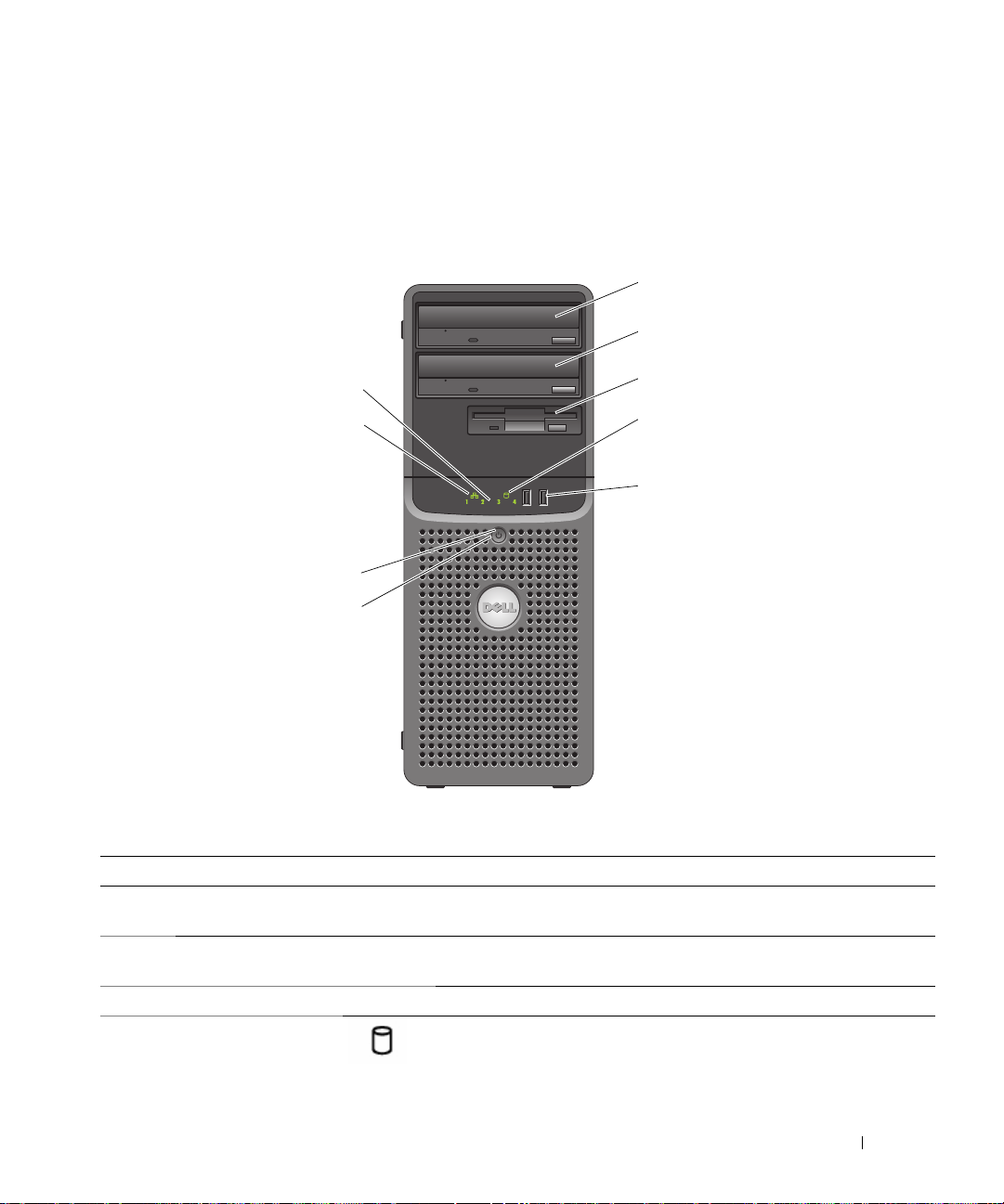
Figure 1-1 shows the controls, indicators, and connectors located on the system's front panel. Table 1-2
provides component descriptions.
Figure 1-1. Front-Panel Features and Indicators
2
9
8
7
6
Table 1-2. Front-Panel Components
Item Component Icon Description
1 upper 5.25-inch drive
bay
2 lower 5.25-inch drive
bay
3 flex bay Holds a diskette drive or an optional third hard drive.
4 hard-drive activity
indicator
Holds an optical drive.
Holds an optional optical or half-height tape drive, or a fourth hard
drive (requires mounting bracket).
Indicates hard drive activity.
3
4
5
About Your System 11
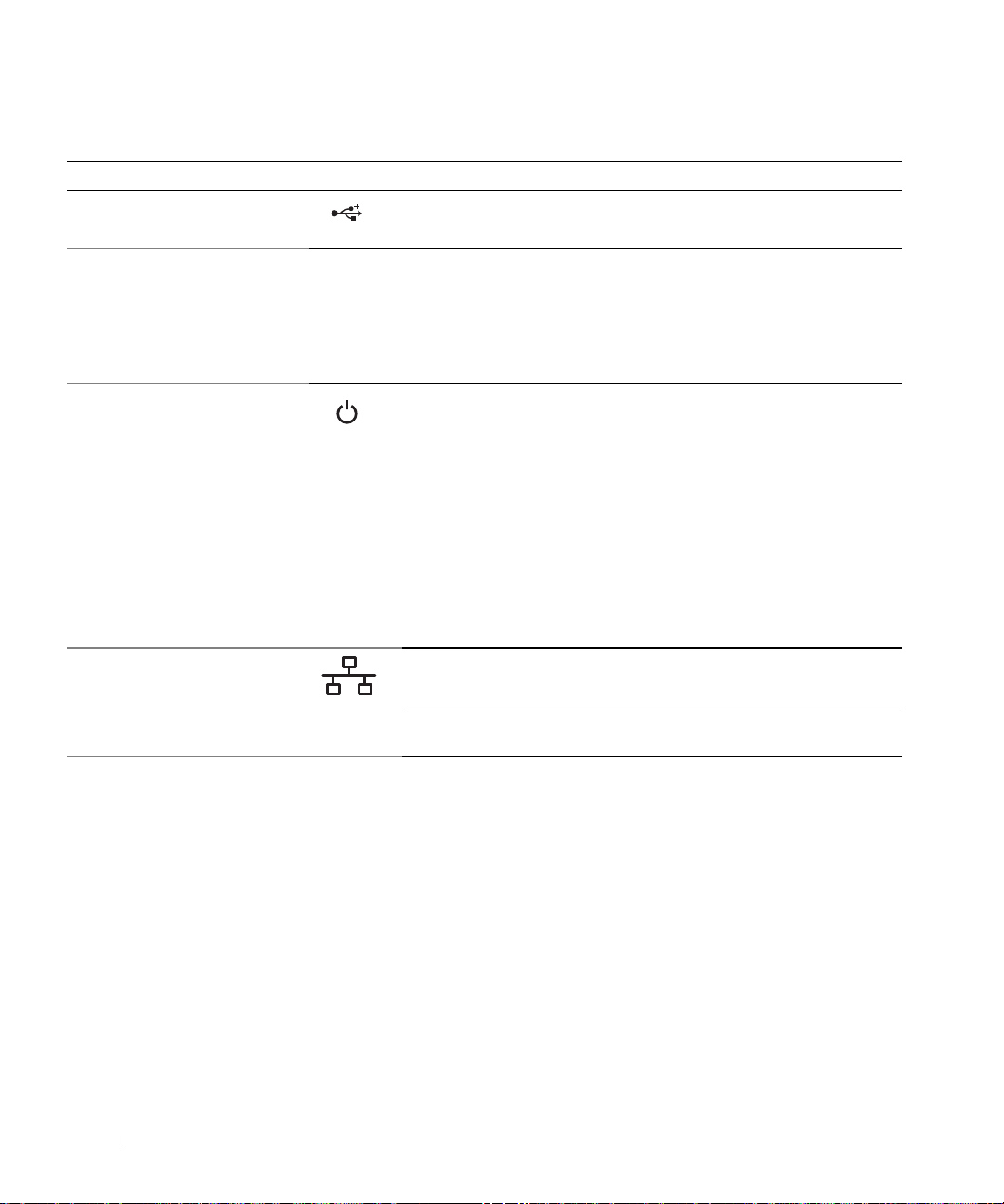
Table 1-2. Front-Panel Components (continued)
Item Component Icon Description
5 USB connectors (2) Connects USB 2.0-compliant devices to the system.
6 power button The power button controls the DC power supply output to the system.
NOTE: If you turn off the system using the power button and the system is
running an ACPI-compliant operating system, the system performs a
graceful shutdown before the power is turned off. If the system is not
running an ACPI-compliant operating system, the power is turned off
immediately after the power button is pressed.
7 power light No light — The system is off.
Steady green — The system is powered on.
Steady amber — The power supply is probably good. Check the
diagnostic indicators to see if the specific problem is identified. See
"Diagnostics Indicator Codes" on page 15.
Blinking amber — The system is powering up.
• If the hard-drive indicator is off, the power supply may need to be
replaced.
• If the hard-drive indicator is on, the system board is faulty. Check
the diagnostic indicators to see if the specific problem is identified.
See "Diagnostics Indicator Codes" on page 15.
8 network link light Lights when the system is linked to a network.
9 diagnostic lights (4) Display light-pattern codes to assist in troubleshooting system
problems.
See "Diagnostics Indicator Codes
" on page 15
.
12 About Your System
Back-Panel Features and Indicators
1
Figure 1-2 shows the connectors located on the system's back panel.
Figure 1-2. Back-Panel Features
2
3
4
1 AC power connector 2 expansion-card slots (5) 3 NIC connector
4 USB connectors (5) 5 video connector 6 parallel connector
7 serial connector
5
6
7
Connecting External Devices
When connecting external devices to your system, follow these guidelines:
• Most devices must be connected to a specific connector and device drivers must be installed before the
device operates properly. (Device drivers are normally included with your operating system software or
with the device itself.) See the documentation that accompanied the device for specific installation
and configuration instructions.
About Your System 13
• Always attach an external device while your system and the device are turned off. Next, turn on any
external devices before turning on the system (unless the documentation for the device specifies
otherwise).
See "Using the System Setup Program" on page 27 for information about enabling, disabling, and
configuring I/O ports and connectors.
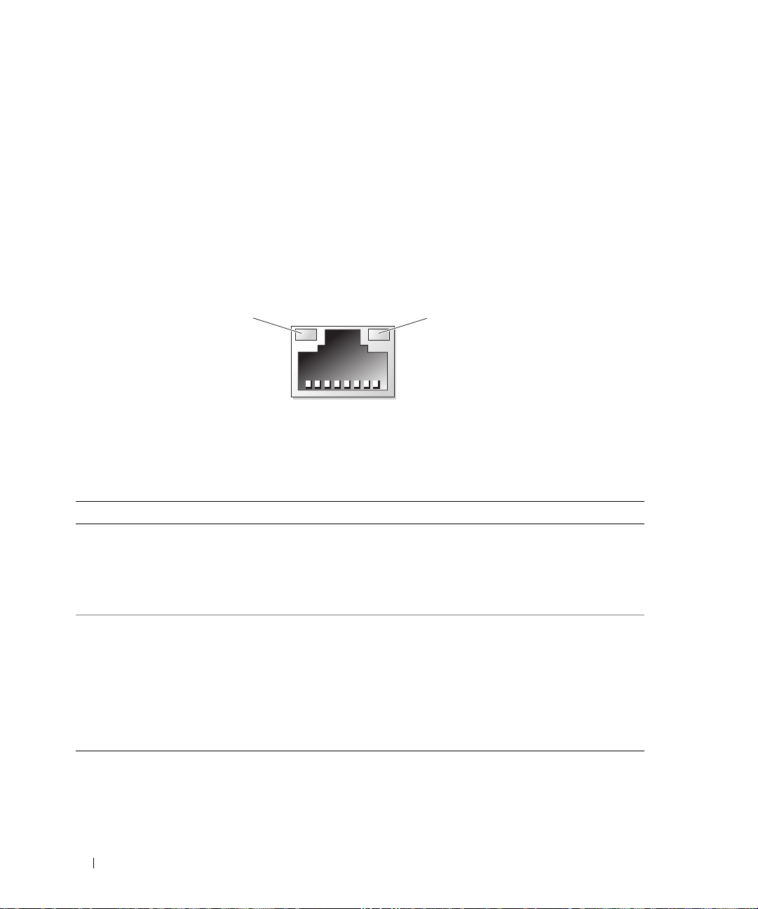
NIC Indicator Codes
The NIC on the back panel has an indicator that provides information on network activity and link
status. See Figure 1-3. Table 1-3 lists the NIC indicator codes.
Figure 1-3. NIC Indicators
12
1 link indicator 2 activity indicator
Table 1-3. NIC Indicator Codes
Indicator Type Indicator Code Description
Activity Off When off at the same time that the link indicator is off,
the NIC is not connected to the network or the NIC is
disabled in the System Setup program. See "Using the
System Setup Program" on page 27.
Blinking Indicates that network data is being sent or received.
Link Off When off at the same time that the activity indicator is
off, the NIC is not connected to the network or the NIC is
disabled in the System Setup program. See "Using the
System Setup Program" on page 27.
Yellow 1000-Mbps connection
Orange 100-Mbps connection
Green 10-Mbps connection
14 About Your System
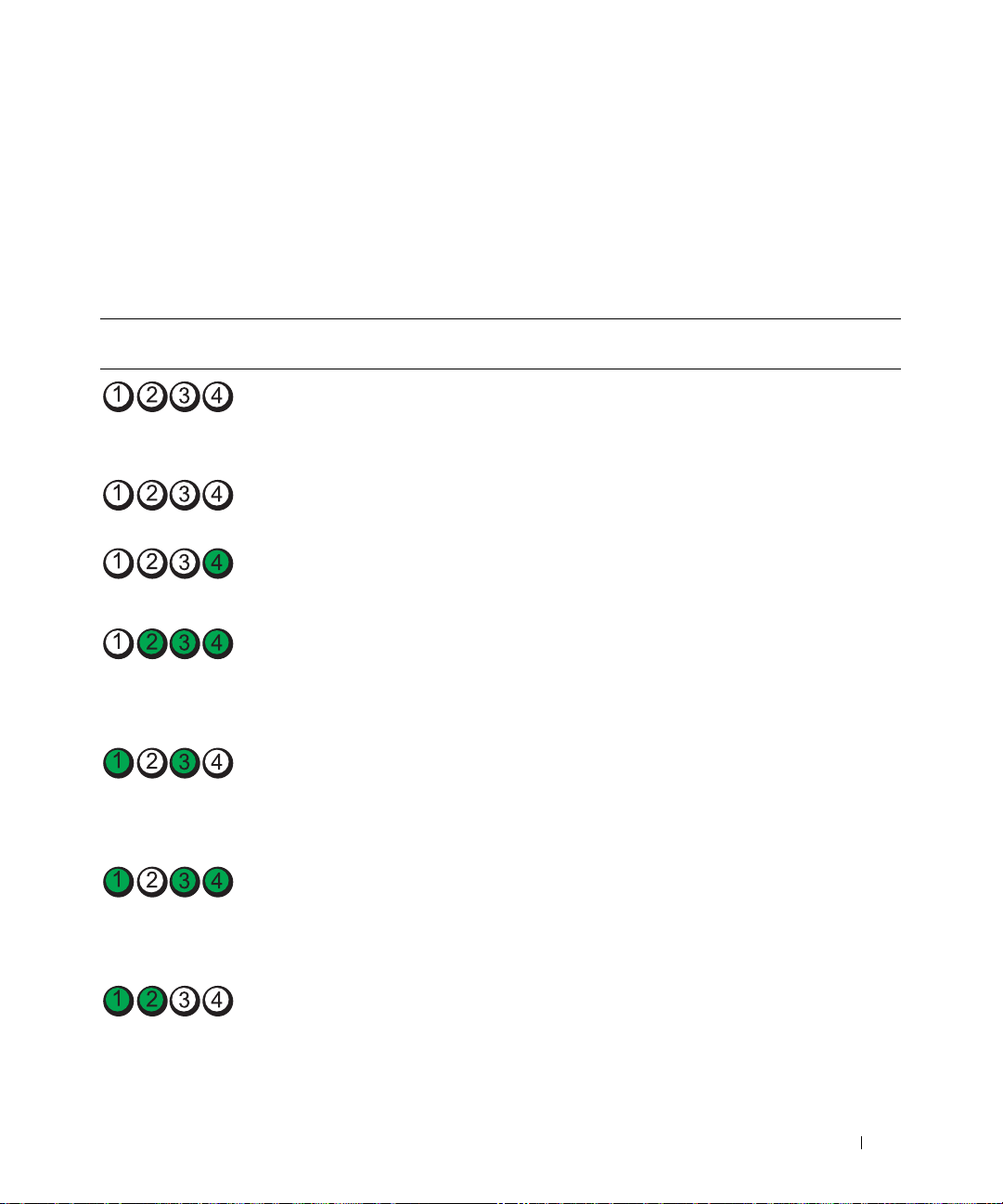
Diagnostics Indicator Codes
The four diagnostic indicator lights on the system front panel display error codes during system startup.
Table 1-4 lists the causes and corrective actions associated with these codes and the power light status
before system POST. Table 1-5 lists the causes and possible corrective actions for these codes during
POST. A highlighted circle indicates the light is on; a non-highlighted circle indicates the light is off.
Table 1-4. Diagnostic Indicator Codes Before POST
Code Power
Light
off No electrical power is
green Normal operation None
off Normal off condition; the
amber The BIOS is not executing. Ensure that the processor is seated correctly and
(blinking)
blinking
amber
(blinking)
amber A possible power supply
(blinking)
amber A possible system board
Causes Corrective Action
Connect the computer to a working electrical
supplied to the computer.
system is connected to an
electrical outlet.
A possible power supply or
power cable failure has
occurred.
failure has occurred.
failure has occurred.
outlet.
If the problem is still not resolved, see "Getting
Help" on page 123.
Press the power button to turn the computer on.
If the system does not turn on and the power light
is off, see "Getting Help" on page 123.
restart the system. See "Microprocessor" on
page 73).
If the problem persists, see "Getting Help" on
page 123.
Check the power supply connections and the
condition of cables. See "Installing the Power
Supply" on page 82.
If the problem persists, see "Getting Help" on
page 123.
Verify that both power supply cables are plugged in
to the system board. See "Installing the Power
Supply" on page 82.
If the problem persists, see "Getting Help" on
page 123.
See "Getting Help" on page 123.
(blinking)
About Your System 15
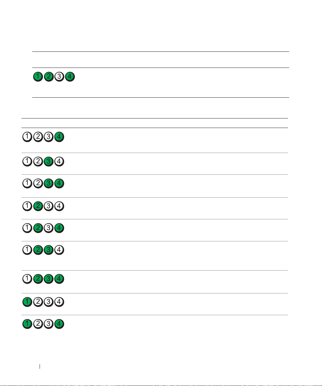
Table 1-4. Diagnostic Indicator Codes Before POST (continued)
Code Power
Light
off A processor mismatch exists. See "Troubleshooting the Microprocessors" on
(blinking)
Table 1-5. Diagnostic Indicator Codes During POST
Code Causes Corrective Action
BIOS checksum failure
detected; system is in recovery
mode.
Possible processor failure. See "Troubleshooting the Microprocessors" on page 110.
Memory failure. See "Troubleshooting System Memory" on page 103.
Possible expansion card failure. See "Troubleshooting Expansion Cards" on page 109.
Possible video failure. See "Getting Help" on page 123.
Causes Corrective Action
page 110.
Ensure that all network cards and connections are functioning
properly. See "Troubleshooting Your System" on page 95.
If the problem persists, see "Getting Help" on page 123.
Diskette drive or hard drive
failure.
Possible USB failure. See "Troubleshooting a USB Device" on page 99.
No memory modules detected. See "Troubleshooting System Memory" on page 103.
System board failure. See "Getting Help" on page 123.
16 About Your System
Ensure that the diskette drive and hard drives are properly
connected. See "Hard Drives" on page 48 and "Diskette Drive"
on page 63 for information on the drives installed in your
system.
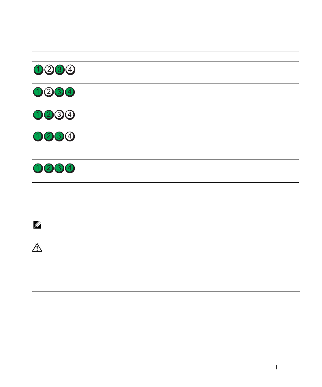
Table 1-5. Diagnostic Indicator Codes During POST (continued)
Code Causes Corrective Action
Memory configuration error. See "Troubleshooting System Memory" on page 103.
Possible system board resource
and/or system board hardware
failure.
Possible system resource
configuration error.
Other failure. Ensure that the diskette drive, optical drive, and hard drives are
The system is in a normal
operating condition after
POST.
See "Troubleshooting IRQ Assignment Conflicts" on page 96. If
the problem persists, see "Getting Help" on page 123.
See "Troubleshooting Your System" on page 95.
If the problem persists, see "Getting Help" on page 123.
properly connected. See "Troubleshooting Your System" on
page 95 for the appropriate drive installed in your system.
If the problem persists, see "Getting Help" on page 123.
Information only.
System Messages
System messages appear on the screen to notify you of a possible problem with the system. Table 1-6 lists
the system messages that can occur and the probable cause and corrective action for each message.
NOTE: If you receive a system message that is not listed in Table 1-6, check the documentation for the application
that is running when the message appears or the operating system's documentation for an explanation of the
message and recommended action.
CAUTION: Only trained service technicians are authorized to remove the system cover and access any of the
components inside the system. See your Product Information Guide for complete information about safety
precautions, working inside the computer, and protecting against electrostatic discharge.
Table 1-6. System Messages
Message Causes Corrective Actions
Alert! Air temperature
sensor not detected.
The front panel thermal diode cable is
improperly installed or has failed.
Verify that cables are firmly seated in the
connectors on the front I/O panel and
the system board. See "Front I/O Panel
(Service Only Parts Procedure)" on
page 89.
About Your System 17

Table 1-6. System Messages (continued)
Message Causes Corrective Actions
Alert! Cable not detected
in INTRUDER connector.
Alert! FAN_CCAG was not
detected.
Alert! FAN_FRONT was not
detected.
Alert! FAN_HDD was not
detected.
Alert! FAN_MEM was not
detected.
Alert! FAN_PSU was not
detected.
Alert! Cover was
previously removed.
Alert! Previous FAN_CCAG
failure.
Alert! Previous FAN_FRONT
failure.
Alert! Previous FAN_HDD
failure.
Alert! Previous FAN_MEM
failure.
Alert! Previous FAN_PSU
failure.
Alert! Previous thermal
event.
Alert! Previous voltage
failure.
The chassis intrusion switch is not
connected to the system board.
Specified fan is missing, faulty, or
improperly installed.
• FAN_CCAG — card fan
• FAN_FRONT — front fan
• FAN_HDD — hard-drive fan for
optional fourth hard drive
• FAN_MEM — memory fan
The power supply fan is faulty. See "Getting Help" on page 123.
The system cover has been opened. Information only. To reset, enter the
Specified fan failed before last system
startup.
• FAN_CCAG — card fan
• FAN_FRONT — front fan
• FAN_HDD — hard-drive fan for
optional fourth hard drive
• FAN_MEM — memory fan
• FAN_PSU — power supply fan
BIOS detected a thermal event before
the last system startup.
Sensor detected voltage out of range
before last system startup.
Verify that the chassis intrusion switch
cable is firmly seated in the INTRUDER
connector on the system board. See
"Installing the Chassis Intrusion Switch"
on page 87.
See "Troubleshooting System Cooling
Problems" on page 102.
System Setup program. See "Using the
System Setup Program" on page 27.
Information only.
Ensure that thermal grease is applied to
the heat sink and the heat sink is
installed properly. Ensure that the
system fans are functioning properly. See
"Replacing the Processor" on page 75 and
"Troubleshooting System Cooling
Problems" on page 102.
Information only.
18 About Your System

Table 1-6. System Messages (continued)
Message Causes Corrective Actions
Alert! Processor thermal
probe failure detected.
BIOS Update Attempt
Failed!
CPUs with different cache
sizes detected!
The processor thermal probe has
See "Getting Help" on page 123.
failed.
Remote BIOS update attempt failed. Retry the BIOS update. If problem
persists, see "Getting Help" on page 123.
Microprocessors with different cache
sizes are installed.
Ensure that all microprocessors have the
same cache size and that they are
properly installed. See "Microprocessor"
on page 73.
Decreasing available
memory
DIMM pairs must be matched
in size, speed, and
technology. The following
DIMM pair is mismatched:
DIMM x and DIMM y.
Faulty or improperly installed memory
modules.
Mismatched or unmatched DIMMs
installed; faulty or improperly seated
memory module(s).
See "Troubleshooting System Memory"
on page 103.
Ensure that all pairs of memory modules
are of the same type and size and that
they are properly installed. See
"Memory" on page 76. If the problem
persists, see "Troubleshooting System
Memory" on page 103.
DIMMs must be populated in
sequential order beginning
with slot 1. The following
DIMM is electrically
The specified DIMM is inaccessible to
the system due to its location. DIMMs
must be populated in sequential order,
beginning with slot 1.
Populate 2 or 4 DIMMs sequentially
beginning with slot 1. See "Memory" on
page 76.
isolated: DIMM x.
DIMMs should be installed
in pairs. Pairs must be
matched in size, speed,
and technology.
Mismatched or unmatched DIMMs
installed; faulty or improperly seated
memory module(s). The system will
operate in a degraded mode with
reduced ECC protection. Only
memory installed in channel 0 will be
Ensure that all pairs of memory modules
are of the same type and size and that
they are properly installed. See
"Memory" on page 76. If the problem
persists, see "Troubleshooting System
Memory" on page 103.
accessible.
Dual-rank DIMM paired with
Single-rank DIMM - The
following DIMM/rank has
been disabled by BIOS:
DIMM x Rank y
Mismatched DIMMs installed; faulty
memory module(s). The system has
detected a dual-rank DIMM paired
with a single-rank DIMM. The second
rank of the dual-rank DIMM will be
disabled.
Ensure that all pairs of memory modules
are of the same type and size and that
they are properly installed. See
"Memory" on page 76. If the problem
persists, see "Troubleshooting System
Memory" on page 103.
About Your System 19

Table 1-6. System Messages (continued)
Message Causes Corrective Actions
Diskette drive n seek
failure
Diskette read failure Faulty or improperly inserted diskette. Replace the diskette. If the problem
Diskette subsystem reset
failed
Drive not ready Diskette missing from or improperly
Error: Incorrect memory
configuration. DIMMs must
be installed in pairs of
matched memory size,
speed, and technology.
Error: Memory failure
detected. Memory size
reduced. Replace the
faulty DIMM as soon as
possible.
FBD training error: The
following branch has been
disabled: Branch x
Gate A20 failure Faulty keyboard controller; faulty
Incorrect configuration settings in the
System Setup program.
Faulty or improperly installed diskette
drive.
Loose diskette drive interface cable, or
loose power cable.
Faulty or improperly installed
diskette.
inserted in diskette drive.
Mismatched or unmatched DIMMs
installed; faulty or improperly seated
memory module(s).
Faulty or improperly seated memory
module(s).
The specified branch (channel pair)
contains DIMMs that are
incompatible with each other.
system board.
Run the System Setup program to
correct the settings. See "Using the
System Setup Program" on page 27.
Replace the diskette. If the problem
persists, see "Troubleshooting a Diskette
Drive" on page 105.
Reseat diskette drive interface cable, or
power cable. See "Troubleshooting a
Diskette Drive" on page 105.
persists, see "Troubleshooting a Diskette
Drive" on page 105.
Replace the diskette. If the problem
persists, see "Troubleshooting a Diskette
Drive" on page 105.
Replace the diskette. If the problem
persists, see "Troubleshooting a Diskette
Drive" on page 105.
Ensure that all pairs of memory modules
are of the same type and size and that
they are properly installed. See
"Memory" on page 76. If the problem
persists, see "Troubleshooting System
Memory" on page 103.
See "Troubleshooting System Memory"
on page 103.
Ensure that only Dell-qualified memory
is used. Dell recommends purchasing
memory upgrade kits directly from
www.dell.com or your Dell sales agent to
ensure compatibility.
See "Getting Help" on page 123.
20 About Your System

Table 1-6. System Messages (continued)
Message Causes Corrective Actions
General failure The operating system is unable to
carry out the command.
n
IDE primary drive
found
Invalid configuration
information - please run
SETUP program
Invalid NVRAM
configuration, Resource
Re-allocated
Keyboard Controller
failure
Manufacturing mode
detected
MEMBIST failure - The
following DIMM/rank has
been disabled by BIOS:
DIMM x Rank y
Memory address line
failure at
value
expecting
Memory double word logic
failure at
value
expecting
Memory odd/even logic
failure at
value
expecting
Memory write/read failure
address
at
expecting
Memory tests terminated by
keystroke.
address
address
address,
, read
value
not
, read
value
, read
value
read
value
value
IDE cables are not properly seated, or
drive missing.
System has detected invalid
configuration.
System detected and corrected a
resource conflict.
Faulty keyboard controller; faulty
system board
System is in manufacturing mode. Reboot to take the system out of
Faulty memory module(s). See "Troubleshooting System Memory"
Faulty or improperly installed memory
modules.
POST memory test terminated by
pressing the spacebar.
This message is usually followed by
specific information. Note the
information and take the appropriate
action to resolve the problem.
See "Troubleshooting an Optical Drive"
on page 106.
Remove the RTCST jumper if it is
installed. See Figure 6-1 for the jumper
location.
No action is required.
See "Getting Help" on page 123.
manufacturing mode.
on page 103.
See "Troubleshooting System Memory"
on page 103.
Information only.
About Your System 21

Table 1-6. System Messages (continued)
Message Causes Corrective Actions
No boot device available Faulty or missing optical/diskette
drive subsystem, hard drive, or harddrive subsystem, or no boot disk in
drive A.
No boot sector on hard
drive
No timer tick interrupt Faulty system board. See "Getting Help" on page 123.
Northbound merge error -
The following DIMM has
been disabled by BIOS:
DIMM x
Not a boot diskette No operating system on diskette. Use a bootable diskette.
PCIe Degraded Link Width
Error: Embedded
nn
Bus#
Expected Link Width is
Actual Link Width is
PCIe Degraded Link Width
Error: Slot
Expected Link Width is
Actual Link Width is
PCIe Training Error:
Embedded
Bus#
PCIe Training Error:
Slot
/Dev#nn/Func
n
nn
/Dev#nn/Funcn
n
n
n
n
Incorrect configuration settings in
System Setup program, or no
operating system on hard drive.
The specified DIMM was unable to
establish a successful data link with
the memory controller.
Faulty or improperly installed PCIe
card in the specified slot.
n
Faulty or improperly installed PCIe
card in the specified slot.
n
Faulty or improperly installed PCIe
card in the specified slot.
Use a bootable diskette, CD, or hard
drive. If the problem persists, see
"Troubleshooting a Diskette Drive" on
page 105, "Troubleshooting an Optical
Drive" on page 106, and
"Troubleshooting a Hard Drive" on
page 107. See "Using the System Setup
Program" on page 27 for information
about setting the order of boot devices.
Check the hard-drive configuration
settings in the System Setup program.
See "Using the System Setup Program"
on page 27. If necessary, install the
operating system on your hard drive. See
your operating system documentation.
See "Troubleshooting System Memory"
on page 103.
Reseat the PCIe card in the specified
slot number. See "Expansion Cards" on
page 70. If the problem persists, see
"Getting Help" on page 123.
Reseat the PCIe card in the specified
slot number. See "Expansion Cards" on
page 70. If the problem persists, see
"Getting Help" on page 123.
Reseat the PCIe card in the specified
slot number. See "Expansion Cards" on
page 70. If the problem persists, see
"Getting Help" on page 123.
22 About Your System

Table 1-6. System Messages (continued)
Message Causes Corrective Actions
PCI BIOS failed to install PCI device BIOS (Option ROM)
checksum failure is detected during
shadowing. Loose cables to expansion
card(s); faulty or improperly installed
expansion card.
Plug & Play Configuration
Error
Read fault
Requested sector not found
Remote configuration
update attempt failed
ROM bad checksum = address Expansion card improperly installed or
n
SATA port
not found
Sector not found
Seek error
Seek operation failed
Shutdown failure Shutdown test failure. See "Troubleshooting System Memory"
hard disk drive
Error encountered in initializing PCI
device; faulty system board.
The operating system cannot read
from the diskette or hard drive, the
system could not find a particular
sector on the disk, or the requested
sector is defective.
System unable to process Remote
Configuration request.
faulty.
SATA cables are not properly seated,
or drive missing.
Faulty diskette or hard drive. See "Troubleshooting a Diskette Drive"
Reseat the expansion cards. Ensure that
all appropriate cables are securely
connected to the expansion cards. If the
problem persists, see "Troubleshooting
Expansion Cards" on page 109.
Install the RTCRST jumper and reboot
the system. See Figure 6-1 for jumper
location. If the problem persists, see
"Troubleshooting Expansion Cards" on
page 109.
Replace the diskette. Ensure that the
diskette and hard drive cables are
properly connected. See
"Troubleshooting a USB Device" on
page 99, "Troubleshooting a Diskette
Drive" on page 105, or "Troubleshooting
a Hard Drive" on page 107 for the
appropriate drive(s) installed in your
system.
Retry Remote Configuration.
Reseat the expansion cards. Ensure that
all appropriate cables are securely
connected to the expansion cards. If the
problem persists, see "Troubleshooting
Expansion Cards" on page 109.
See "Troubleshooting a Hard Drive" on
page 107.
on page 105 or "Troubleshooting a Hard
Drive" on page 107 for the appropriate
drive(s) installed in your system.
on page 103.
About Your System 23

Table 1-6. System Messages (continued)
Message Causes Corrective Actions
The amount of system
memory has changed
The following DIMM pair is
not compatible with the
memory controller: DIMM x
and DIMM y
The following DIMMs are
not compatible: DIMM x and
DIMM y
Time-of-day clock stopped Faulty battery or faulty chip. See "Troubleshooting the System
Time-of-day not set please run SETUP program
Timer chip counter 2
failed
Unsupported CPU
combination
Unsupported CPU stepping
detected
Utility partition not
available
Warning! No microcode
update loaded for
processor
n
Memory has been added or removed
or a memory module may be faulty.
The specified DIMM(s) are
incompatible with the system.
The specified DIMM(s) are
incompatible with the system.
Incorrect Time or Date settings; faulty
system battery.
Faulty system board. See "Getting Help" on page 123.
Microprocessor(s) is not supported by
the system.
The <F10> key was pressed during
POST, but no utility partition exists
on the boot hard drive.
Microcode update failed. Update the BIOS firmware. See "Getting
If memory has been added or removed,
this message is informative and can be
ignored. If memory has not been added
or removed, check the SEL to determine
if single-bit or multi-bit errors were
detected and replace the faulty memory
module. See "Troubleshooting System
Memory" on page 103.
Ensure that only Dell-qualified memory
is used. Dell recommends purchasing
memory upgrade kits directly from
www.dell.com or your Dell sales agent to
ensure compatibility.
Ensure that only ECC FBD1 memory is
used. Dell recommends purchasing
memory upgrade kits directly from
www.dell.com or your Dell sales agent to
ensure compatibility.
Battery" on page 102.
Check the Time and Date settings. See
"Using the System Setup Program" on
page 27. If the problem persists, replace
the system battery. See "System Battery"
on page 79.
Install a supported microprocessor or
microprocessor combination. See
"Microprocessor" on page 73.
Create a utility partition on the boot
hard drive. See the CDs that came with
your system.
Help" on page 123.
24 About Your System

Table 1-6. System Messages (continued)
Message Causes Corrective Actions
Warning: The current
memory configuration is
not optimal. Dell
recommends a population of
2 or 4 DIMMs. DIMMs should
be populated sequentially
starting in slot 1.
Write fault
Write fault on selected
drive
System has detected a legal but nonoptimal population of DIMMs. The
system will run with all memory
accessible but will experience suboptimal performance.
Faulty diskette, optical/diskette drive
assembly, hard drive, or hard-drive
subsystem.
Populate 2 or 4 DIMMs sequentially
beginning with slot 1. See "Memory" on
page 76.
See "Troubleshooting a Diskette Drive"
on page 105, "Troubleshooting an
Optical Drive" on page 106, or
"Troubleshooting a Hard Drive" on
page 107.
NOTE: For the full name of an abbreviation or acronym used in this table, see the "Glossary" on page 149.
Warning Messages
A warning message alerts you to a possible problem and prompts you to respond before the system
continues a task. For example, before you format a diskette, a message will warn you that you may lose all
data on the diskette. Warning messages usually interrupt the task and require you to respond by typing
(yes) or
n (no).
NOTE: Warning messages are generated by either the application or the operating system. For more information,
see the documentation that accompanied the operating system or application.
y
Diagnostics Messages
When you run system diagnostics, an error message may result. Diagnostic error messages are not
covered in this section. Record the message on a copy of the Diagnostics Checklist in "Getting Help" on
page 123, and then follow the instructions in that section for obtaining technical assistance.
Alert Messages
Systems management software generates alert messages for your system. Alert messages include
information, status, warning, and failure messages for drive, temperature, fan, and power conditions. For
more information, see the systems management software documentation.
About Your System 25

26 About Your System
Using the System Setup Program
After you set up your system, run the System Setup program to familiarize yourself with your system
configuration and optional settings. Record the information for future reference.
You can use the System Setup program to:
• Change the system configuration stored in NVRAM after you add, change, or remove hardware
• Set or change user-selectable options—for example, the time or date
• Enable or disable integrated devices
• Correct discrepancies between the installed hardware and configuration settings
Entering the System Setup Program
1
Turn on or restart your system.
2
Press <F2> immediately after you see the following message display briefly on the screen:
<F2> = System Setup
If your operating system begins to load before you press <F2>, allow the system to finish booting,
and then restart your system and try again.
NOTE: To ensure an orderly system shutdown, see the documentation that accompanied your operating
system.
Responding to Error Messages
You can enter the System Setup program by responding to certain error messages. If an error message
appears while the system is booting, make a note of the message. Before entering the System Setup
program, see "System Messages" on page 17 for an explanation of the message and suggestions for
correcting errors.
NOTE: After installing a memory upgrade, it is normal for your system to send a message the first time you
start your system.
Using the System Setup Program 27
Using the System Setup Program
Table 2-1 lists the keys that you use to view or change information on the System Setup program screens
and to exit the program.
Table 2-1. System Setup Program Navigation Keys
Keys Action
Up arrow or <Shift><Tab> Moves to the previous field.
Down arrow or <Tab> Moves to the next field.
Spacebar, <+>, <
right arrows
<Esc> Exits the System Setup program and restarts the
<F1> Displays the System Setup program
NOTE: For most of the options, any changes that you make are recorded but do not take effect until you restart the
system.
–>, left and
Cycles through the settings in a field. In many fields,
you can also type the appropriate value.
system if any changes were made.
's help file.
System Setup Options
Main Screen
When you enter the System Setup program, the main System Setup program screen appears. See
Figure 2-1.
28 Using the System Setup Program
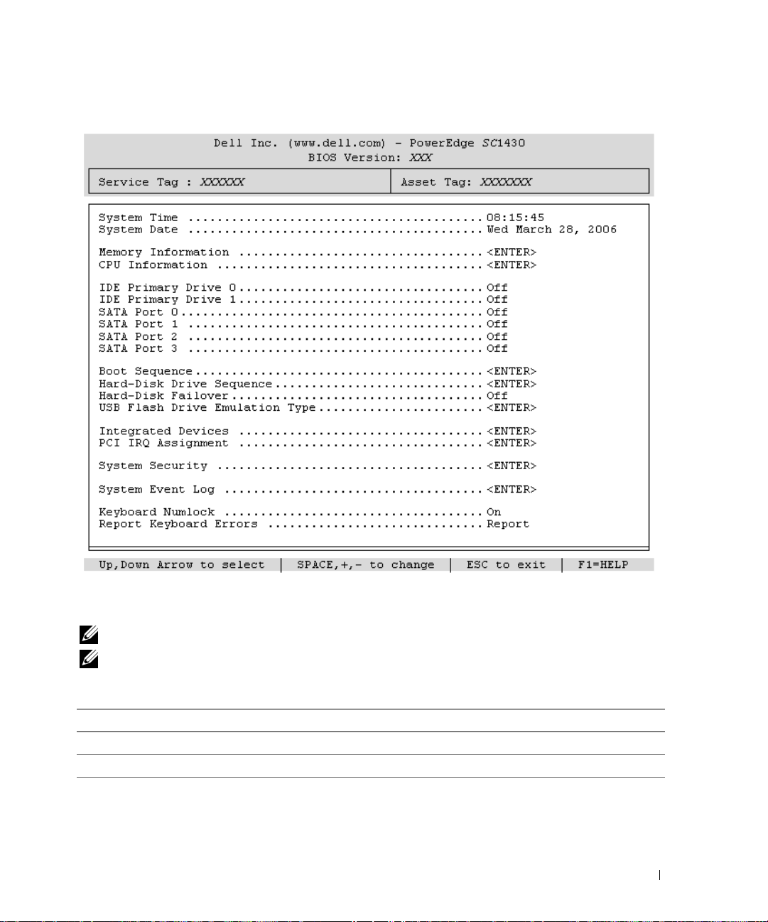
Figure 2-1. Main System Setup Program Screen
Table 2-2 lists the options and descriptions for the information fields that appear on the main System
Setup program screen.
NOTE: The options for the System Setup program change based on the system configuration.
NOTE: The System Setup program defaults are listed under their respective options, where applicable.
Table 2-2. System Setup Program Options
Option Description
System Time Resets the time on the system's internal clock.
System Date Resets the date on the system's internal calendar.
Memory Information Displays information related to installed system and video memory, including size,
type, and speed of memory modules, system video memory size and system
memory test option.
Using the System Setup Program 29

Table 2-2. System Setup Program Options (continued)
Option Description
CPU Information Displays information related to microprocessors (speed, cache size, and so on).
Enable or disable Hyper-Threading technology, if supported, by changing the
setting of the Logical Processor option. See Table 2-3.
SATA Port X Displays type and capacity of SATA drive attached to Port X on the system board.
Boot Sequence Determines the order in which the system searches for boot devices during system
startup. Available options can include the diskette drive, CD drive, hard drives, and
network. Only the first IDE device found will be available in the boot sequence.
Hard-Disk Drive Sequence
Hard-Disk Failover
(
Off
default)
USB Flash Drive Type
Auto
default)
(
Integrated Devices See "Integrated Devices Screen" on page 32.
PCI IRQ Assignment Displays a screen to change the IRQ assigned to each of the integrated devices on
System Security Displays a screen to configure the system password and setup password features,
System Event Log Select to view or clear the System Event Log (SEL). See "System Event Log" on
Keyboard NumLock
(
On
default)
Report Keyboard Errors
Report
default)
(
Specifies the order in which hard drives are configured in the system. The first hard
drive in the system will be the bootable C: drive in DOS/DOS-like operating
systems.
When this field is set to On and the first hard drive is not available, the system
attempts to boot from the other hard drives in the order specified in Hard-Disk
Drive Sequence before searching for the next device in Boot Sequence. This
feature may be used to boot to a mirrored drive in a software RAID 1 configuration.
Determines the emulation type for a USB flash drive. Hard disk allows the USB
flash drive to act as a hard drive. Floppy allows the USB flash drive to act as a
removal diskette drive. Auto automatically chooses an emulation type.
the PCI bus, and any installed expansion cards that require an IRQ.
AC power recovery, and chassis intrusion detection. See Table 2-5. See "Using the
System Password" on page 36 and "Using the Setup Password" on page 38 for more
information.
page 34.
Determines whether your system starts up with the NumLock mode activated on
101- or 102-key keyboards (does not apply to 84-key keyboards).
Enables or disables reporting of keyboard errors during the POST. Select Report for
host systems that have keyboards attached. Select Do Not Report to suppress all
error messages relating to the keyboard or keyboard controller during POST. This
setting does not affect the operation of the keyboard itself if a keyboard is attached
to the system.
30 Using the System Setup Program
Loading...