


 Loading...
Dell Dimension E520 Service Manual
Dell™ Dimension™ E520 Service Manual
Before You Begin
About Your Computer
Technical Overview
Specifications
Advanced Troubleshooting
System Setup
Removing and Installing Parts
Notes, Notices, and Cautions
NOTE: A NOTE indicates important information that helps you make better use of your computer.
NOTICE: A NOTICE indicates either potential damage to hardware or loss of data and tells you how to avoid the problem.
CAUTION: A CAUTION indicates a potential for property damage, personal injury, or death.
If you purchased a Dell™ n Series computer, any references in this document to Microsoft® Windows® operating systems are not applicable.
Information in this document is subject to change without notice. © 2006 Dell Inc. All rights reserved.
Reproduction in any manner whatsoever without the written permission of Dell Inc. is strictly forbidden.
Trademarks used in this text: Dell, the DELL logo, and Dimension are trademarks of Dell Inc.; Intel, Pentium, and SpeedStep are registered trademarks of Intel Corporation; Microsoft and Windows are registered trademarks of Microsoft Corporation.
Other trademarks and trade names may be used in this document to refer to either the entities claiming the marks and names or their products. Dell Inc. disclaims any proprietary interest in trademarks and trade names other than its own.
Model DCTA
July 2006 Rev. A00
file:///T|/htdocs/systems/dimE520/en/SM_EN/index.htm[10/16/2012 1:04:33 PM]

Before You Begin: Dell Dimension E520 Service Manual
Back to Contents Page
Before You Begin
Dell™ Dimension™ E520 Service Manual
 Getting Started
 Recommended Tools
 Turning Off Your Computer
 Before Working Inside Your Computer
Getting Started
This manual provides procedures for removing and replacing the components in your computer. Unless otherwise noted, each procedure assumes that the following conditions exist:
 You have performed the steps in Turning Off Your Computer and Before Working Inside Your Computer.
 You have read the safety information in your Dell™ Product Information Guide.
 A component can be replaced by performing the removal procedure in reverse order.
Recommended Tools
The procedures in this document may require the following tools:
 Small flat-blade screwdriver
 Phillips screwdriver
 Flash BIOS update program (download)
Turning Off Your Computer
NOTICE: To avoid losing data, save and close any open files and exit any open programs before you turn off your computer.
1.Shut down the operating system:
a.Save and close any open files, exit any open programs, click the Start button, and then click Shutdown.
b.In the Shut Down Windows window, select Shut down.
The computer turns off after the operating system shutdown process finishes.
2.Ensure that the computer and any attached devices are turned off. If your computer and attached devices did not automatically turn off when you shut down your operating system, press and hold the power button for 4 seconds.
Before Working Inside Your Computer
file:///T|/htdocs/systems/dimE520/en/SM_EN/before.htm[10/16/2012 1:04:35 PM]

Before You Begin: Dell Dimension E520 Service Manual
Use the following safety guidelines to help protect your computer from potential damage and to help ensure your own personal safety.
CAUTION: Before you begin any of the procedures in this section, follow the safety instructions in the
Product Information Guide.
CAUTION: Handle components and cards with care. Do not touch the components or contacts on a card. Hold a card by its edges or by its metal mounting bracket. Hold a component such as a processor by its edges, not by its pins.
NOTICE: Only a certified service technician should perform repairs on your computer. Damage due to servicing that is not authorized by Dell is not covered by your warranty.
NOTICE: When you disconnect a cable, pull on its connector or on its strain-relief loop, not on the cable itself. Some cables have a connector with locking tabs; if you are disconnecting this type of cable, press in on the locking tabs before you disconnect the cable. As you pull connectors apart, keep them evenly aligned to avoid bending any connector pins. Also, before you connect a cable, ensure that both connectors are correctly oriented and aligned.
NOTICE: To avoid damaging the computer, perform the following steps before you begin working inside the computer.
1. Turn off your computer. See Turning Off Your Computer.
NOTICE: To disconnect a network cable, first unplug the cable from your computer, and then unplug it from the network port or device.
2.Disconnect any telephone or telecommunication lines from the computer.
3.Disconnect your computer and all attached devices from their electrical outlets, and then press the power button to ground the system board.
NOTICE: Before touching anything inside your computer, ground yourself by touching an unpainted metal surface, such as the metal at the back of the computer. While you work, periodically touch an unpainted metal surface to dissipate any static electricity that could harm internal components.
Back to Contents Page
file:///T|/htdocs/systems/dimE520/en/SM_EN/before.htm[10/16/2012 1:04:35 PM]
About Your Computer: Dell Dimension E520 Service Manual
Back to Contents Page
About Your Computer
Dell™ Dimension™ E520 Service Manual
 Front View of the Computer
 Back View of the Computer
 Back Panel Connectors
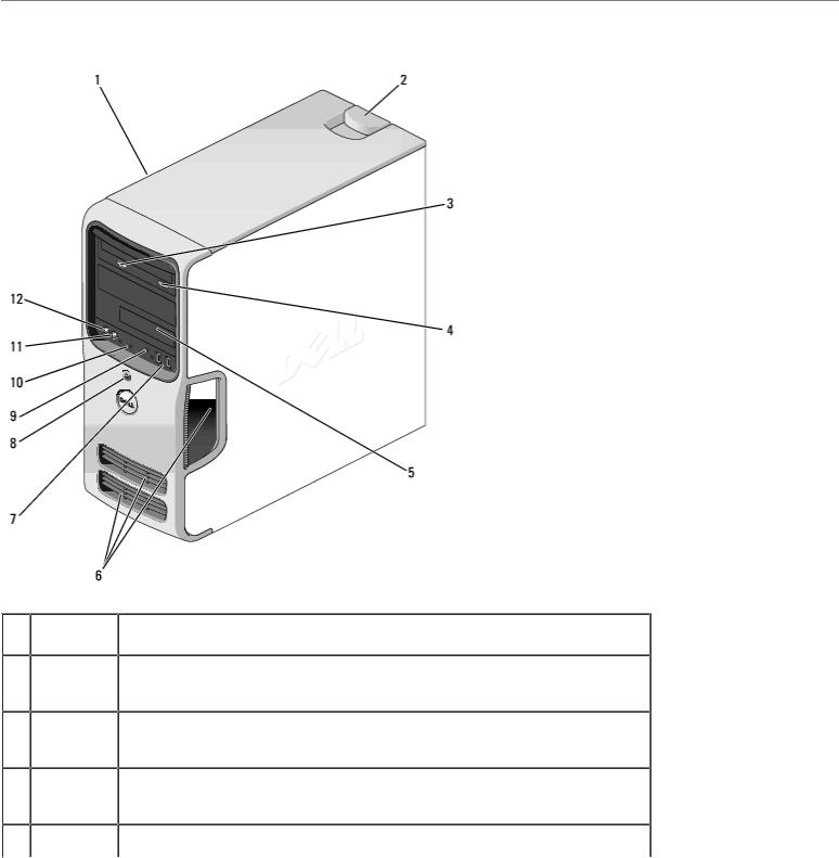
Front View of the Computer
1 |
Service |
Use the Service Tag to identify your computer when you access the Dell |
|
Tag |
Support website or contact support. |
2 |
cover |
Use this latch to remove the cover. |
|
release |
|
|
latch |
|
3 |
CD or DVD |
The CD or DVD drive light is on when the computer reads data from, or writes |
|
activity |
data to the CD or DVD drive. |
|
light |
|
4 |
CD or DVD |
Press the CD or DVD eject button to eject a disc from the CD or DVD drive. |
|
eject |
|
|
button |
|
5 |
FlexBay |
Can contain an optional floppy drive or optional Media Card Reader. |
file:///T|/htdocs/systems/dimE520/en/SM_EN/about.htm[10/16/2012 1:04:38 PM]
About Your Computer: Dell Dimension E520 Service Manual
|
drive |
|
|
6 |
vents |
For adequate cooling, do not block any of the vents. |
|
|
|
NOTICE: Ensure that there is a minimum of two inches of space between all |
|
|
|
vents and any objects near the vents. |
|
|
|
NOTICE: Keep the vent area clean and dust-free to ensure that the system is |
|
|
|
adequately ventilated. Use only a dry cloth to clean the vent area to avoid |
|
|
|
water damage to the system. |
|
7 |
USB 2.0 |
Use the front USB connectors for devices that you connect occasionally, such |
|
|
connectors |
as flash memory keys, cameras, or bootable USB devices. For more |
|
|
(2) |
information on booting to a USB device see System Setup Options. |
|
|
|
NOTE: It is recommended that you use the back USB connectors for devices |
|
|
|
that typically remain connected, such as printers and keyboards. |
|
8 |
power |
Press the power button to turn on the computer. |
|
|
button |
|
|
|
|
NOTICE: To avoid losing data, do not use the power button to turn off the |
|
|
|
computer. Instead, perform an operating system shutdown. |
|
9 |
hard drive |
The hard drive light is on when the computer reads data from or writes data |
|
|
activity |
to the hard drive. The light may also be on when a device such as a CD player |
|
|
light |
is operating. |
|
10 |
diagnostic |
Use the sequence of the diagnostic lights to help you troubleshoot a problem |
|
|
lights (4) |
with your computer (see Diagnostic Lights). |
|
11 |
headphone |
Use the headphone connector to attach headphones and most kinds of |
|
|
connector |
speakers. |
|
12 |
microphone |
Use the microphone connector to attach a personal computer microphone for |
|
|
connector |
voice or musical input into a sound or telephony program. |
|
|
|
|
|
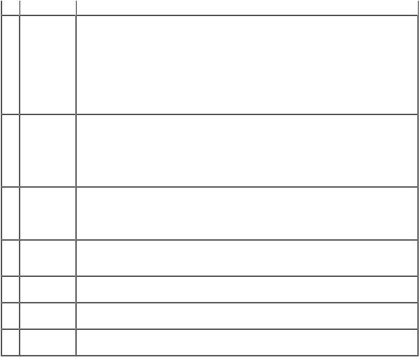
Back View of the Computer
file:///T|/htdocs/systems/dimE520/en/SM_EN/about.htm[10/16/2012 1:04:38 PM]
About Your Computer: Dell Dimension E520 Service Manual
1 |
power |
Insert the power cable. |
|
connector |
|
2 |
back I/O |
Plug USB, network, VGA monitor, and audio devices into the appropriate |
|
connectors |
connectors (see Back Panel Connectors). |
3 |
card slots (4) |
Access connectors for installed PCI or PCI Express cards. |
|
|
|
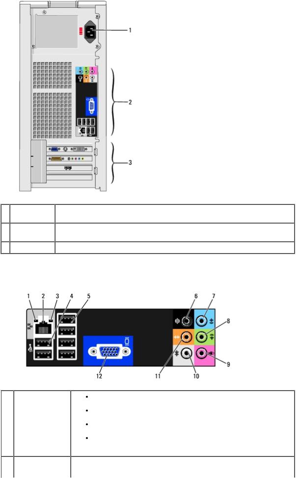
Back Panel Connectors
1 |
link integrity |
Green — A good connection exists between a 10-Mbps network |
|
light |
and the computer. |
|
|
Orange — A good connection exists between a 100-Mbps network |
|
|
and the computer. |
|
|
Yellow — A good connection exists between a 1000-Mbps (1- |
|
|
Gbps) network and the computer. |
|
|
Off — The computer is not detecting a physical connection to the |
|
|
network. |
2 |
network adapter |
NOTICE: Do not plug a telephone cable into the network connector. |
|
connector |
file:///T|/htdocs/systems/dimE520/en/SM_EN/about.htm[10/16/2012 1:04:38 PM]

About Your Computer: Dell Dimension E520 Service Manual
|
|
Use the network adapter connector to attach your computer to a |
|
|
network or broadband device. Connect one end of a network cable to |
|
|
either a network jack or your network or broadband device, and then |
|
|
connect the other end of the network cable to the network adapter |
|
|
connector on your computer. A click indicates that the network cable |
|
|
has been securely attached. |
|
|
On computers with an additional network card, use the connectors on |
|
|
the card and on the back of the computer when setting up multiple |
|
|
network connections (such as a separate intraand extranet). |
|
|
NOTE: It is recommended that you use Category 5 wiring and |
|
|
connectors for your network. If you must use Category 3 wiring, force |
|
|
the network speed to 10 Mbps to ensure reliable operation. |
3 |
network activity |
Flashes a yellow light when the computer is transmitting or receiving |
|
light |
network data. A high volume of network traffic may make this light |
|
|
appear to be in a steady "on" state. |
4 |
USB 2.0 |
Use the back, rear-dual USB connectors for devices that typically remain |
|
connectors (2) |
connected, such as printers and keyboards. |
|
(rear dual) |
|
|
|
NOTE: It is recommended that you use the front USB connectors for |
|
|
devices that you connect occasionally, such as joysticks, cameras, or |
|
|
bootable USB devices. |
5 |
USB 2.0 |
Use the back, rear-quad USB connectors for devices that typically |
|
connectors (4) |
remain connected, such as printers and keyboards. |
|
(rear quad) |
|
|
|
NOTE: It is recommended that you use the front USB connectors for |
|
|
devices that you connect occasionally, such as joysticks, cameras, or |
|
|
bootable USB devices. |
6 |
surround sound |
Use the (black) surround sound connector to attach multichannel- |
|
connector |
capable speakers. |
|
|
On computers with a sound card, use the connector on the card. |
7 |
line-in connector |
Use the (blue) line-in connector to attach a record/playback device such |
|
|
as a cassette player, CD player, or VCR. |
|
|
On computers with a sound card, use the connector on the card. |
8 |
line- |
Use the (green) line-out connector to attach headphones and most |
|
out/headphone |
speakers with integrated amplifiers. |
|
connector |
On computers with a sound card, use the connector on the card. |
|
|
|
9 |
microphone |
Use the (pink) microphone connector to attach a personal computer |
|
connector |
microphone for voice or musical input into a sound or telephony |
|
|
program. |
|
|
On computers with a sound card, use the connector on the card. |
10 |
side surround |
Use the (gray) side surround sound connector to attach multichannel- |
|
sound connector |
capable speakers. The side-surround output provides enhanced |
|
|
surround audio for computers with 7.1 speakers. |
|
|
On computers with a sound card, use the connector on the card. |
11 |
center/subwoofer |
Use the (orange) center/subwoofer connector to attach a center speaker |
|
LFE connector |
or a single subwoofer. |
On computers with a sound card, use the connector on the card.
NOTE: The LFE (Low Frequency Effects) Audio channel, found in digital surround sound audio schemes, carries only low frequency information of 80 Hz and below. The LFE channel drives a subwoofer to provide extremely low bass extension. Systems not using subwoofers can shunt the LFE information to the main speakers in the surround sound setup.
file:///T|/htdocs/systems/dimE520/en/SM_EN/about.htm[10/16/2012 1:04:38 PM]
About Your Computer: Dell |
Dimension E520 Service Manual |
12 VGA connector |
Use the integrated video connector to attach your video monitor |
|
(optional). |
|
On computers with a video card, use the connector on the card. |
Back to Contents Page
file:///T|/htdocs/systems/dimE520/en/SM_EN/about.htm[10/16/2012 1:04:38 PM]
Technical Overview: Dell Dimension E520 Service Manual
Back to Contents Page
Technical Overview
Dell™ Dimension™ E520 Service Manual
 Inside View of Your Computer
 System Board Components
 Power Supply DC Connector Pin Assignments
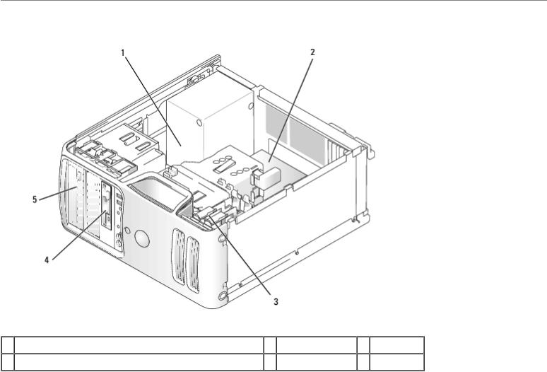
Inside View of Your Computer
1 |
power supply |
2 |
system board |
3 hard drive |
4 |
floppy drive (optional) or media card reader (optional) |
5 |
CD or DVD drive |
|
|
|
|
|
|
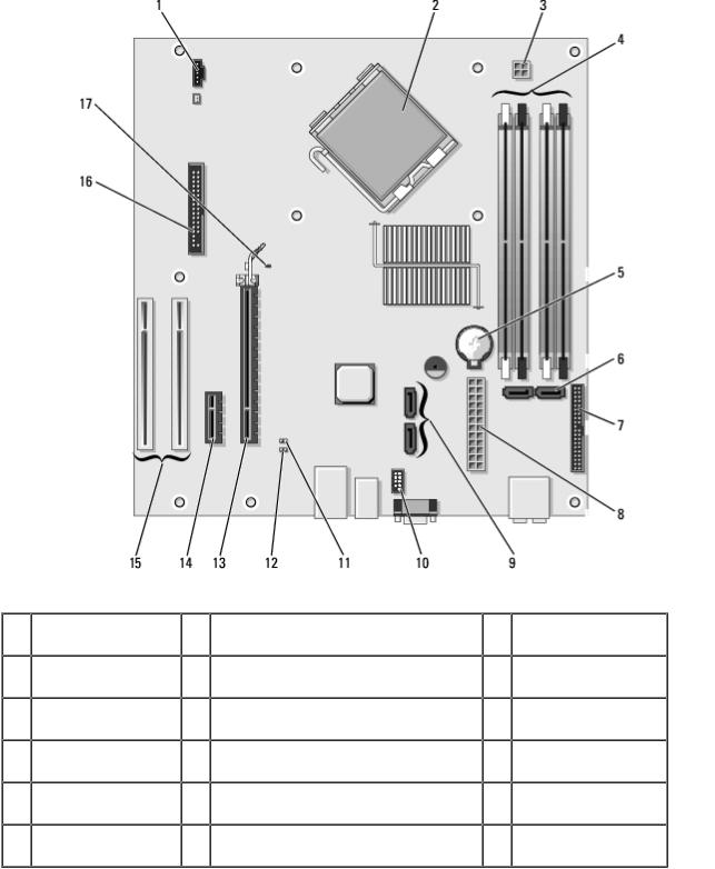
System Board Components
file:///T|/htdocs/systems/dimE520/en/SM_EN/techov.htm[10/16/2012 1:04:43 PM]
Technical Overview: Dell Dimension E520 Service Manual
1 |
CPU fan connector |
2 |
processor and heat sink connector |
3 |
processor power |
|
|
|
|
|
connector |
4 |
memory module |
5 |
battery socket (BATTERY) |
6 |
SATA Connectors |
|
connectors |
|
|
|
SATA0 and SATA1 |
7 |
front panel I/O |
8 |
main power connector |
9 |
SATA connectors |
|
connector |
|
|
|
SATA4 and SATA5 |
10 |
FlexBay USB |
11 |
clear CMOS jumper (CLRCMOS) |
12 |
password jumper |
|
connector |
|
|
|
(CLRPSWD) |
13 |
PCI Express x16 |
14 |
PCI Express x1 card connector |
15 |
PCI card connector |
|
card connector |
|
|
|
|
16 |
floppy drive |
17 |
Standby LED (near blue lever on PCI |
|
|
|
connector (FLOPPY) |
|
Express x16 connector) |
|
|
|
|
|
|
|
|
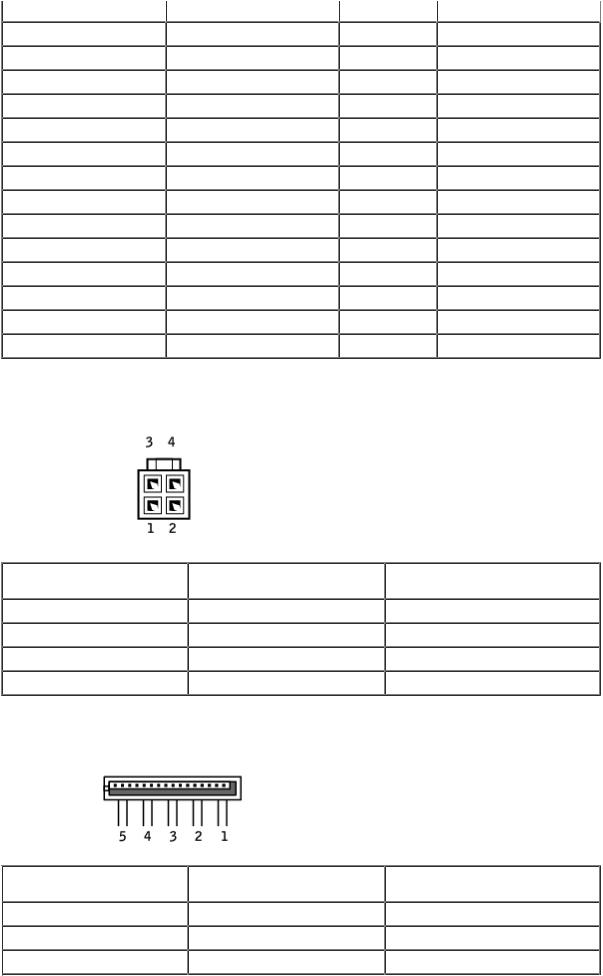
Power Supply DC Connector Pin Assignments
file:///T|/htdocs/systems/dimE520/en/SM_EN/techov.htm[10/16/2012 1:04:43 PM]
Technical Overview: Dell Dimension E520 Service Manual
DC Power Connector P1
Pin Number |
Signal Name |
Color |
Wire Gauge |
1 |
+3.3 VDC |
Orange |
18-AWG |
2 |
+3.3 VDC |
Orange |
18-AWG |
3 |
COM |
Black |
18-AWG |
4 |
+5 VDC |
Red |
18-AWG |
5 |
COM |
Black |
18-AWG |
6 |
+5 VDC |
Red |
18-AWG |
7 |
COM |
Black |
18-AWG |
8 |
POK |
Gray |
18-AWG |
9 |
+5 VFP |
Purple |
18-AWG |
file:///T|/htdocs/systems/dimE520/en/SM_EN/techov.htm[10/16/2012 1:04:43 PM]
Technical Overview: Dell Dimension E520 Service Manual |
|
|
|
|
||
10 |
|
+12 VB DC |
|
White |
|
18-AWG |
|
|
|
||||
11 |
|
+12VB DC |
|
White |
|
18-AWG |
|
|
|
||||
12 |
|
+3.3 VDC |
|
Orange |
|
18-AWG |
13 |
|
+3.3 VDC |
|
Orange |
|
18-AWG |
14 |
|
-12 VDC |
|
Blue |
|
18-AWG |
15 |
|
COM |
|
Black |
|
18-AWG |
16 |
|
PS-ON |
|
Green |
|
18-AWG |
17 |
|
COM |
|
Black |
|
18-AWG |
18 |
|
COM |
|
Black |
|
18-AWG |
19 |
|
COM |
|
Black |
|
18-AWG |
20 |
|
N/C |
|
N/C |
|
18-AWG |
21 |
|
+5 VDC |
|
Red |
|
18-AWG |
22 |
|
+5 VDC |
|
Red |
|
18-AWG |
23 |
|
+5 VDC |
|
Red |
|
18-AWG |
24 |
|
COM |
|
Black |
|
18-AWG |
DC Power Connector P2
Pin Number |
Signal Name |
18-AWG Wire |
1 |
COM |
Black |
2 |
COM |
Black |
3 |
+12 VA DC |
Yellow |
4 |
+12 VA DC |
Yellow |
DC Power Connect P3, P5, P8, and P9
Pin Number |
Signal Name |
18-AWG Wire |
1 |
+3.3 VDC |
Orange |
2 |
COM |
Black |
3 |
+5 VDC |
Red |
file:///T|/htdocs/systems/dimE520/en/SM_EN/techov.htm[10/16/2012 1:04:43 PM]
Technical Overview: Dell Dimension E520 Service Manual |
|
|
4 |
COM |
Black |
5 |
+12 VB DC |
White |
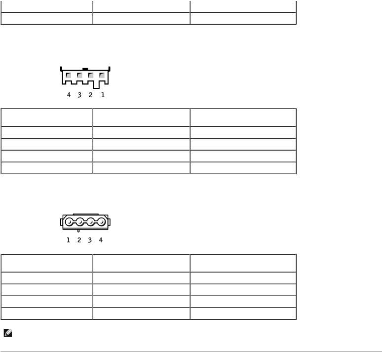
DC Power Connector P7
Pin Number |
Signal Name |
18-AWG Wire |
1 |
+5 VDC |
Red |
2 |
COM |
Black |
3 |
COM |
Black |
4 |
+12 A VDC |
Yellow |
DC Power Connector P10
Pin Number |
Signal Name |
18-AWG Wire |
1 |
+12 VA DC |
Yellow |
2 |
COM |
Black |
3 |
COM |
Black |
4 |
+5V DC |
Red |
NOTE: The P10 connector is intended for use with PCI Express graphics cards that have power requirements exceeding 75 watts.
Back to Contents Page
file:///T|/htdocs/systems/dimE520/en/SM_EN/techov.htm[10/16/2012 1:04:43 PM]
Specifications: Dell Dimension E520 Service Manual
Back to Contents Page
Specifications
Dell™ Dimension™ E520 Service Manual
Processor |
|
Processor type |
Intel® Pentium® 4 |
|
Intel® Pentium® D |
|
Intel® Core™ 2 Duo |
|
NOTE: Not all Pentium 4 processors |
|
support Hyper-Threading technology. |
Level 1 (L1) cache |
32 KB |
Level 2 (L2) cache |
1 MB for Pentium 4 5XX processors (with |
|
Hyper Threading) |
|
2 MB for Pentium 4 6XX processors (with |
|
Hyper Threading) |
|
2 x 2 MB for Pentium D 9XX processors |
|
(with dual core) |
|
2 x 1 MB for Pentium D 8XX processors |
|
(with dual core) |
|
256K for Celeron® D 3XX processors |
|
2 MB for Intel Core™ E6400 processors |
|
and earlier |
|
4 MB for Intel Core™ E6600 processors |
|
and later |
Memory |
|
Type |
533-MHz, 667-MHz, and 800-MHz dual |
|
DDR2 unbuffered SDRAM |
Memory connectors |
four |
Memory capacities |
256 MB, 512 MB, or 1 GB non-ECC |
Maximum memory |
4 GB |
|
NOTE: See Addressing Memory With 4- |
|
GB Configurations to verify the amount of |
|
memory available to the operating |
|
system. |
BIOS address |
F0000h |
Computer Information |
|
Chipset |
Intel G965 Express Chipset |
RAID Support |
RAID 1 (Mirroring) |
DMA channels |
eight |
Interrupt levels |
24 |
file:///T|/htdocs/systems/dimE520/en/SM_EN/specs.htm[10/16/2012 1:04:46 PM]

Specifications: Dell Dimension E520 Service Manual |
|
|
|
|
BIOS chip (NVRAM) |
|
4 MB |
|
|||
|
NIC |
|
integrated network interface capable of |
|
|
||
|
|
|
10/100 communication |
|
System clock |
|
533-MHz, 800-MHz, or 1066-MHz data |
|
|
|
rate |
|
Video |
|
|
|
Type |
|
integrated Intel® Graphics Media |
|
|
|
Accelerator X3000 (Intel® GMA X3000) |
|
|
|
PCI Express |
|
Audio |
|
|
|
Type |
|
Sigmatel 9227 |
|
Expansion Bus |
|
|
|
Bus type |
|
PCI 2.3 |
|
|
|
PCI Express x1 and x16 |
|
Bus speed |
|
PCI: 33 MHz |
|
|
|
PCI Express: |
|
|
|
x1 slot bidirectional speed - 500 |
|
|
|
MB/s |
|
|
|
x16 slot bidirectional speed - 8 |
|
|
|
GB/s |
|
PCI |
|
|
|
connectors |
|
two |
|
connector size |
|
120 pins |
|
connector data width (maximum) |
|
32 bits |
|
PCI Express |
|
|
|
connector |
|
one x1 |
|
connector size |
|
36 pins |
|
connector data width (maximum) |
|
1 PCI Express lane |
|
PCI Express |
|
|
|
connector |
|
one x16 |
|
connector size |
|
164 pins |
|
connector data width (maximum) |
|
16 PCI Express lanes |
|
Drives |
|
|
|
|
|
|
|
Externally accessible: |
|
|
|
Bays |
|
two 5.25-inch drive bays |
|
|
|
one 3.5-inch drive bay (FlexBay) |
|
Available devices |
|
Serial ATA drives (4), floppy drive, USB |
|
|
|
memory devices, CD/DVD drive, and |
|
|
|
Media Card Reader |
|
|
|
|
file:///T|/htdocs/systems/dimE520/en/SM_EN/specs.htm[10/16/2012 1:04:46 PM]
Specifications: Dell Dimension E520 Service Manual |
|
|
Internally accessible: |
|
two bays for 1-inch high serial ATA hard |
|
||
|
|
drives |
Connectors |
|
|
|
|
|
External connectors: |
|
|
Video |
|
15-hole connector |
Network adapter |
|
RJ-45 connector |
USB |
|
two front-panel and six back-panel USB |
|
|
2.0-compliant connectors |
Audio |
|
six connectors for 7.1 support |
System board connectors: |
|
|
Serial ATA (SATA) |
|
four 7-pin connectors |
FlexBay Drive |
|
one USB 10-pin header (with one pin |
|
|
removed for keying) for optional Media |
|
|
Card Reader (3.5-inch bay device) |
Floppy drive |
|
one 34-pin connector |
Fan |
|
one 5-pin connector |
PCI 2.3 |
|
two 120-pin connectors |
PCI Express x1 |
|
one 36-pin connector |
PCI Express x16 |
|
one 164-pin connector |
 Controls and Lights
Power button
Power light
 Hard drive access light
Link integrity light (on integrated network adapter)
 push button
green light — Blinking green in sleep state; solid green for power-on state.
amber light — Blinking amber indicates a problem with the power supply inside the computer. If the system cannot boot and there is a solid amber light, a problem with the system board may exist (see Power Lights).
 green
green
green light — A good connection exists between the network and the computer.
off (no light) — The computer is not detecting a physical connection to the network.
Activity light (on integrated network adapter)
 Diagnostic lights Standby power light
 Power
Power
DC power supply:
Wattage
 yellow blinking light
four lights on the front panel (see Diagnostic Lights)
 STBYLED on the system board
 305 W
305 W
file:///T|/htdocs/systems/dimE520/en/SM_EN/specs.htm[10/16/2012 1:04:46 PM]
Specifications: Dell Dimension E520 Service Manual
Maximum heat dissipation
Voltage (see the safety instructions located in the Product Information Guide for important voltage setting information)
 Backup battery
 Physical
Height
 Width
Width
Depth
 Weight
 Environmental
Temperature:
Operating
Storage
 Relative humidity
Maximum vibration:
Operating Storage
 Maximum shock: Operating
 1040 BTU/hr
Manually selectable: 90 to 135 V and 180 to 265 V at 50/60 Hz
 3-V CR2032 lithium coin cell
 41.4 cm (16.3 inches)
18.8 cm (7.4 inches)
 45.7 cm (18.0 inches) 12.7 kg (28.0 lb)
 10° to 35°C (50° to 95°F)
  –40° to 65°C (–40° to 149°F)
  20% to 80% (noncondensing)
 5 to 350 Hz at 0.0002 G2/Hz
5 to 500 Hz at 0.001 to 0.01 G2/Hz
40 G +/- 5% with pulse duration of 2 msec +/- 10% (equivalent to 20 in/sec [51 cm/sec])
Storage |
105 G +/- 5% with pulse duration of 2 |
|
msec +/- 10% (equivalent to 50 in/sec |
|
[127 cm/sec]) |
Altitude: |
|
Operating |
–15.2 to 3048 m (–50 to 10,000 ft) |
Storage |
–15.2 to 10,668 m (–50 to 35,000 ft) |
|
|
Back to Contents Page |
|
file:///T|/htdocs/systems/dimE520/en/SM_EN/specs.htm[10/16/2012 1:04:46 PM]

Advanced Troubleshooting: Dell Dimension E520 Service Manual
Back to Contents Page
Advanced Troubleshooting
Dell™ Dimension™ E520 Service Manual
 Power Lights
 Diagnostic Lights
 Beep Codes
 System Messages
 Dell Diagnostics
 Drivers
 Resolving Software and Hardware Incompatibilities
Power Lights
CAUTION: Before you begin any of the procedures in this section, follow the safety instructions in the
Product Information Guide.
The power button light located on the front of the computer illuminates and blinks or remains solid to indicate different states:
 If the power light is green and the computer is not responding:
 Ensure the display is connected and powered on.
 If the display is connected and powered on see Diagnostic Lights.
 If the power light is blinking green, the computer is in standby mode. Press a key on the keyboard, move the mouse, or press the power button to resume normal operation.
 If the power light is off, the computer is either turned off or is not receiving power.
 Reseat the power cable in the power connector on the back of the computer and the electrical outlet.
 If the computer is plugged into a power strip, ensure that the power strip is plugged into an electrical outlet and that the power strip is turned on. Also, bypass power protection devices, power strips, and power extension cables to verify that the computer turns on properly.
 Ensure that the electrical outlet is working by testing it with another device, such as a lamp.
 Ensure that the main power cable and front panel cable are securely connected to the system board (see System Board Components).
 If the power light is blinking amber, the computer is receiving electrical power, but an internal power problem might exist.
 Ensure that the voltage selection switch is set to match the AC power at your location (if applicable).
 If the power light is steady amber, a device might be malfunctioning or incorrectly installed.
 Remove and then reinstall the memory modules (see Memory).
 Remove and then reinstall any cards (see Cards).
 Remove and then reinstall the graphics card, if applicable (see Cards).
 Ensure that all power cables are securely connected to the system board (see System Board Components).
file:///T|/htdocs/systems/dimE520/en/SM_EN/adtshoot.htm[10/16/2012 1:04:50 PM]
Advanced Troubleshooting: Dell Dimension E520 Service Manual
Diagnostic Lights
CAUTION: Before you perform any of the procedures in this section, follow the safety instructions in the
Product Information Guide.
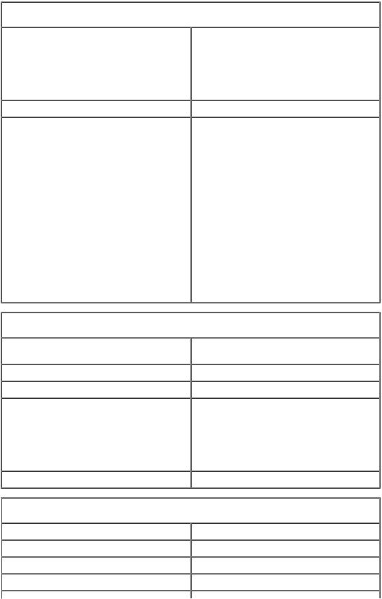
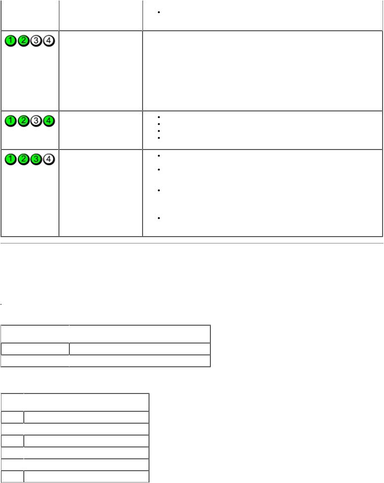
To help you troubleshoot a problem, your computer has four lights labeled 1, 2, 3, and 4 on the front panel (see Front View of the Computer). When the computer starts normally, the lights flash before turning off. If the computer malfunctions, the sequence of the lights helps to identify the problem.
. |
|
|
Light Pattern |
Problem Description |
Suggested Resolution |
|
The computer is in a |
Plug the computer into a working electrical outlet (see Power Lights). |
|
normal "off" condition or |
If the problem persists, contact Dell (see "Contacting Dell" in your |
|
a possible pre-BIOS |
Owner's Manual). |
|
failure has occurred. |
|
|
All four diagnostic lights |
|
|
display solid green and |
|
|
then turn off after the |
|
|
system successfully boots |
|
|
to the operating system. |
|
|
A possible processor |
Reseat the processor (see Processor). |
|
failure has occurred. |
If the problem persists, contact Dell (see "Contacting Dell" in your |
|
|
Owner's Manual). |
|
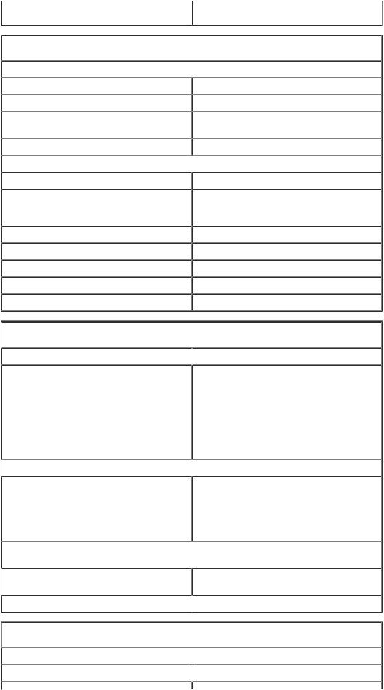
Memory modules are |
If two or more memory modules are installed, remove the modules |
|
detected, but a memory |
(see Removing Memory), then reinstall one module (see Installing |
|
failure has occurred. |
Memory) and restart the computer. If the computer starts normally, |
|
|
continue to install additional memory modules (one at a time) until you |
|
|
have identified a faulty module or reinstalled all modules without |
|
|
error. |
|
|
If available, install properly working memory of the same type into |
|
|
your computer (see Installing Memory). |
|
|
If the problem persists, contact Dell (see "Contacting Dell" in your |
|
|
Owner's Manual). |
|
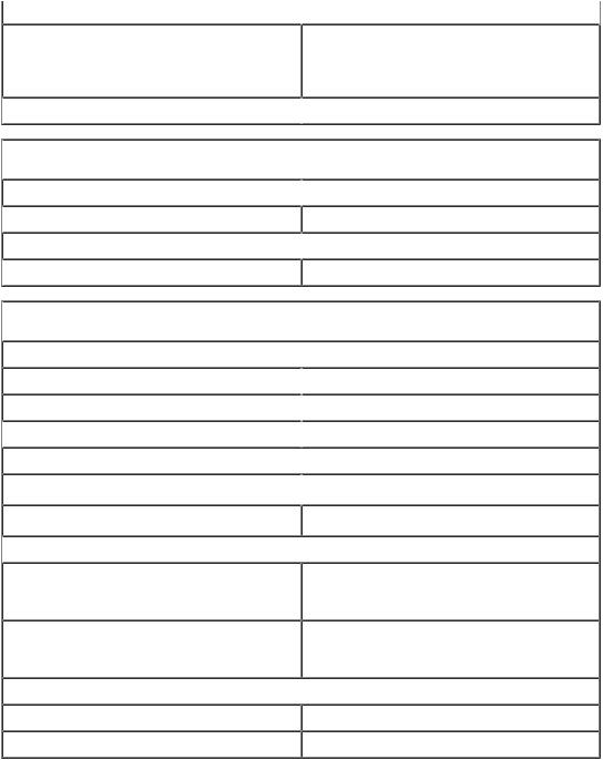
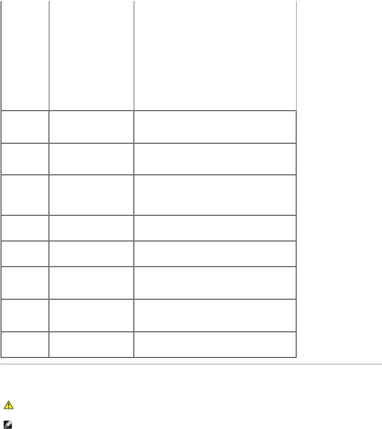
A possible graphics card |
Reseat any installed graphics cards (see Cards). |
|
failure has occurred. |
If available, install a working graphics card into your computer. |
|
|
If the problem persists, contact Dell (see "Contacting Dell" in your |
|
|
Owner's Manual). |
|
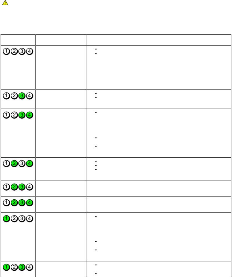
A possible floppy drive or |
Reseat all power and data cables. |
|
hard drive failure has |
|
|
occurred. |
|
|
A possible USB failure |
Reinstall all USB devices and check all cable connections. |
|
has occurred. |
|
|
No memory modules are |
If two or more memory modules are installed, remove the modules |
|
detected. |
(see Removing Memory), then reinstall one module (see Installing |
|
|
Memory) and restart the computer. If the computer starts normally, |
|
|
continue to install additional memory modules (one at a time) until you |
|
|
have identified a faulty module or reinstalled all modules without |
|
|
error. |
|
|
If available, install properly working memory of the same type into |
|
|
your computer (see Installing Memory). |
|
|
If the problem persists, contact Dell (see "Contacting Dell" in your |
|
|
Owner's Manual). |
|
Memory modules are |
Ensure that no special requirements for memory module/connector |
|
detected, but a memory |
placement exist (see Memory). |
|
configuration or |
Ensure that the memory you are using is supported by your computer |
|
|
|
file:///T|/htdocs/systems/dimE520/en/SM_EN/adtshoot.htm[10/16/2012 1:04:50 PM]
Advanced Troubleshooting: Dell Dimension E520 Service Manual |
|
|||
|
compatibility error has |
|
|
(see Memory). |
|
|
|||
|
occurred. |
|
|
If the problem persists, contact Dell (see "Contacting Dell" in your |
|
|
|
|
Owner's Manual). |
|
|
|
|
|
|
A possible expansion card |
1. Determine if a conflict exists by removing an expansion card (not a |
||
|
failure has occurred. |
graphics card) and restarting the computer (see Cards). |
||
|
|
|
|
2. If the problem persists, reinstall the card you removed, then remove a |
|
|
|
|
different card and restart the computer. |
|
|
|
|
3. Repeat this process for each card installed. If the computer starts |
|
|
|
|
normally, troubleshoot the last card removed from the computer for |
|
|
|
|
resource conflicts (see Resolving Software and Hardware |
|
|
|
|
Incompatibilities). |
|
|
|
|
4. If the problem persists, contact Dell (see "Contacting Dell" in your |
|
|
|
|
Owner's Manual). |
|
The system is operating |
Press the power button |
||
|
in quick resume mode. |
Move the mouse |
||
|
|
|
|
Press any key on the keyboard |
|
|
|
|
Press any key on the optional MCE remote control |
|
Another failure has |
Ensure that all hard drive and CD/DVD drive cables are properly |
||
|
occurred. |
connected to the system board (see Drives). |
||
|
|
|
|
If there is an error message on your screen identifying a problem with |
|
|
|
|
a device (such as the floppy drive or hard drive), check the device to |
|
|
|
|
make sure it is functioning properly. |
|
|
|
|
If the operating system is attempting to boot from a device (such as |
|
|
|
|
the floppy drive or hard drive), check system setup (see System |
|
|
|
|
Setup) to make sure the boot sequence is correct for the devices |
|
|
|
|
installed on your computer. |
|
|
|
|
If the problem persists, contact Dell (see "Contacting Dell" in your |
|
|
|
|
Owner's Manual). |
Beep Codes
Your computer might emit a series of beeps during start-up if the monitor cannot display errors or problems. This series of beeps, called a beep code, identifies a problem. For example, beep code 1-3-1 (one possible beep code) consists of one beep, a burst of three beeps, and then one beep. This beep code tells you that the computer encountered a memory problem.
 Reseating the memory modules (see Installing Memory) may correct the following beep code errors. If the problem persists, see "Contacting Dell" in your Owner's Manual for instructions on obtaining technical assistance.
 Code
Code  Cause
Cause
1-3-1 through 2-4-4 Memory not being properly identified or used
 4-3-1
4-3-1  Memory failure above address 0FFFFh
If you experience any of the following non-memory related beep code errors, see "Contacting Dell" in your Owner's Manual for instructions on obtaining technical assistance.
 Code
Code  Cause
Cause
1-1-2 Microprocessor register failure
 1-1-3
1-1-3  NVRAM
NVRAM
1-1-4 ROM BIOS checksum failure
 1-2-1
1-2-1  Programmable interval timer
  1-2-2
1-2-2  DMA initialization failure
1-2-3 DMA page register read/write failure
file:///T|/htdocs/systems/dimE520/en/SM_EN/adtshoot.htm[10/16/2012 1:04:50 PM]
Advanced Troubleshooting: Dell Dimension E520 Service Manual
 3-1-1
3-1-1  Slave DMA register failure
3-1-2 Master DMA register failure
 3-1-3
3-1-3  Master interrupt mask register failure
3-1-4 Slave interrupt mask register failure
 3-2-2
3-2-2  Interrupt vector loading failure
3-2-4 Keyboard Controller Test failure
 3-3-1
3-3-1  NVRAM power loss
3-3-2 NVRAM configuration
 3-3-4
3-3-4  Video Memory Test failure
3-4-1 Screen initialization failure
 3-4-2
3-4-2  Screen retrace failure
3-4-3 Search for video ROM failure
 4-2-1
4-2-1  No time tick
4-2-2 Shutdown failure
 4-2-3
4-2-3  Gate A20 failure
4-2-4 Unexpected interrupt in protected mode
 4-3-3
4-3-3  Timer-chip counter 2 failure
4-3-4 Time-of-day clock stopped  4-4-1
4-4-1  Serial or parallel port test failure
4-4-4 Cache test failure
System Messages
NOTE: If the message you received is not listed in the table, see the documentation for either the operating system or the program that was running when the message appeared.
Message
8042 Gate-
A20 error
Address Line
Short!
 Possible Cause
The keyboard controller failed its test.
An error in the address decoding circuitry in the memory has occurred.
C: Drive
Error
C: Drive
Failure
Cache
Memory Bad,
Do Not
Enable
Cache
CH-2 Timer
Error
The hard drive is not working or is not configured correctly.
The cache memory is not operating.
An error is occurring on the timer on the system board.
CMOS Battery The system configuration
State Low
 Corrective Action
If you receive this message after you make changes in the system setup program, enter the system setup program (see Entering System Setup) and restore the original value(s).
Reseat the memory modules (see Memory).
Ensure that the drive is installed correctly in the computer and defined correctly in the system setup program (see Entering System Setup).
See "Contacting Dell" in your Owner's Manual for instructions on obtaining technical assistance.
See "Contacting Dell" in your Owner's Manual for instructions on obtaining technical assistance.
 Enter the system setup program (see Entering
file:///T|/htdocs/systems/dimE520/en/SM_EN/adtshoot.htm[10/16/2012 1:04:50 PM]
Advanced Troubleshooting: Dell Dimension E520 Service Manual
CMOS
Checksum
Failure
CMOS System
Options Not
Set
CMOS Display
Type
Mismatch
CMOS Memory
Size
Mismatch
CMOS Time
and Date Not
Set
Diskette
Boot Failure
DMA Error
DMA 1 Error
DMA 2 Error
FDD
Controller
Failure
HDD
Controller
Failure
INTR1 Error
INTR2 Error
Invalid Boot
Diskette
Keyboard
Error
KB/Interface
Error
No ROM
Basic
information in the system setup program is incorrect or the battery charge may be low.
Drive A or B is present but has failed the BIOS POST.
Error in the DMA controller on the system board.
The BIOS cannot communicate with the floppy drive or hard drive controller.
An interrupt channel on the system board failed to POST.
The operating system cannot be located on drive A or drive C.
The BIOS has detected a stuck key.
An error occurred with the keyboard connector.
The operating system cannot be located on drive A or drive C.
System Setup), verify the system configuration, and then restart the computer.
Ensure that the drive is installed correctly in the computer and defined correctly in the system setup program (see Entering System Setup). Check the interface cable at both ends.
The keyboard or system board may need to be replaced.
Ensure that the floppy drive or the hard drive is installed correctly in the computer (see Drives) and defined correctly in the system setup program (see Entering System Setup). Check the interface cable at both ends.
The keyboard or system board may need to be replaced.
Enter the system setup program (see Entering System Setup)and confirm that drive A or drive C is properly identified.
Ensure that nothing is resting on the keyboard; if a key appears to be stuck, carefully pry it up. If the problem persists, you may need to replace the keyboard.
Ensure that nothing is resting on the keyboard; if a key appears to be stuck, carefully pry it up. If the problem persists, you may need to replace the keyboard.
Enter the system setup program (see Entering System Setup) and confirm that drive A or drive C is properly identified.
Dell Diagnostics
CAUTION: Before you begin any of the procedures in this section, follow the safety instructions in the
Product Information Guide.
NOTE: The Dell Diagnostics only operate on Dell computers.
Starting the Dell Diagnostics
1. Turn on (or restart) your computer.
file:///T|/htdocs/systems/dimE520/en/SM_EN/adtshoot.htm[10/16/2012 1:04:50 PM]
Advanced Troubleshooting: Dell Dimension E520 Service Manual
2. When the DELL logo appears, press <F12> immediately.
NOTE: Keyboard failure may result when a key is held down for extended periods of time. To avoid possible keyboard failure, press and release <F12> in even intervals to open the Boot Device Menu.
If you wait too long and the operating system logo appears, continue to wait until you see the Microsoft® Windows® desktop, then shut down your computer and try again.
3.At the Boot Device Menu, use the upand down-arrow keys or press the appropriate number on the keyboard to highlight Boot to Utility Partition, and then press <Enter>.
NOTE: The Quickboot feature changes the boot sequence for the current boot only. Upon restart, the computer boots according to the boot sequence specified in system setup.
4.At the Dell Diagnostics Main Menu, left-click with the mouse, or press <Tab> and then <Enter>, to select the test you want to run (see Dell Diagnostics Main Menu).
NOTE: Write down any error codes and problem descriptions exactly as they appear and follow the instructions on the screen.
5.After all tests have completed, close the test window to return to the Dell Diagnostics Main Menu.
6.Close the Main Menu window to exit the Dell Diagnostics and restart the computer.
Dell Diagnostics Main Menu
The following tests can be run from the Dell Diagnostics Main Menu:
Option |
Function |
Express |
Performs a quick test of system devices. The test typically takes 10 to 20 minutes and requires no interaction on |
Test |
your part. Run Express Test first to increase the possibility of tracing the problem quickly. |
Extended |
Performs a thorough check of system devices. The test typically takes an hour or more and peridocially requires |
Test |
your input to answer specific questions. |
Custom |
Tests a specific device in the system and can be used to customize the tests you want to run. |
Test |
|
Symptom |
Lists a number of common symptoms and allows you to select a test based on the symptom of the problem you |
Tree |
are having. |
For any problem encountered during a test, a message appears with an error code and a description of the problem. Write down the error code and problem description exactly as it appears and follow the instructions on the screen. If you cannot resolve the problem, see "Contacting Dell" in your Owner's Manual for instructions on obtaining technical assistance.
NOTE: The Service Tag for your computer is located at the top of each test screen. When contacting Dell support, have your Service Tag ready.
The following tabs provide additional information for tests run from the Custom Test or Symptom Tree option:
Tab |
Function |
Results |
Displays the results of the test and any error conditions encountered. |
Errors |
Displays error conditions encountered, error codes, and the problem description. |
Help |
Describes the test and any requirements for running the test. |
Configuration |
Displays the hardware configuration for the selected device. |
file:///T|/htdocs/systems/dimE520/en/SM_EN/adtshoot.htm[10/16/2012 1:04:50 PM]
Advanced Troubleshooting: Dell Dimension E520 Service Manual
(Custom The Dell Diagnostics obtains configuration information for all devices from system setup, memory, and Test various internal tests, and it displays the information in the device list in the left pane of the screen. only)
|
NOTE: The device list may not display the names of all the components installed on your computer or all |
|
devices attached to your computer. |
Parameters |
Allows you to customize the test, if applicable, by changing the test settings. |
(Custom Test only)
Drivers
What Is a Driver?
A driver is a program that controls a device such as a printer, mouse, or keyboard. All devices require a driver program.
A driver acts as a translator between the device and any other programs that use the device. Each device has its own set of specialized commands that only the driver for that device recognizes.
Required drivers are already installed on your computer—no further installation or configuration is needed.
Many drivers, such as the keyboard driver, come with your Microsoft® Windows® operating system. You may need to install drivers if you:
Upgrade your operating system.
Reinstall your operating system.
Connect or install a new device.
Identifying Drivers
If you experience a problem with any device, identify whether the driver is the source of your problem and, if necessary, update the driver.
Windows XP
1.Click the Start button, then click Control Panel.
2.Under Pick a Category, click Performance and Maintenance.
3.Click System.
4.In the System Properties window, click the Hardware tab.
5.Click Device Manager.
6.Scroll down the list of devices and check for an exclamation point (a circle with a [!]) next to the device name.
If an exclamation point appears next to the device name, you may need to reinstall the driver or install a new driver.
Reinstalling Drivers
file:///T|/htdocs/systems/dimE520/en/SM_EN/adtshoot.htm[10/16/2012 1:04:50 PM]
Loading...