


Dell™ OptiPlex™ 760 Service Manual
Mini Tower Computer
Desktop Computer
Small Form Factor Computer
Ultra Small Form Factor Computer

Back to Contents Page
Advanced Features
Dell™ OptiPlex™ 760 Service Manual
LegacySelect Technology Control
Manageability
Physical Security
Trusted Platform Module (TPM)
Security Management Software
Computer Tracking Software
About Smart Cards and Fingerprint Readers
Hyperthreading and Multi-Core Technology
Power Management for Windows XP and Windows Vista
LegacySelect Technology Control
LegacySelect technology control offers legacy-full, legacy-reduced, or legacy-free solutions based on common platforms, hard drive images, and help desk procedures. Control is provided to the administrator through system setup, Dell OpenManage™ IT Assistant, or Dell custom-factory integration.
LegacySelect allows administrators to electronically activate or deactivate connectors and media devices that include serial and USB connectors, a parallel connector, a floppy drive, PCI slots, and a PS/2 mouse. Connectors and media devices that are deactivated make resources available. You must restart the computer to effect the changes.
Manageability
DASH
DASH (Desktop and mobile Architecture for System Hardware) is a Desktop Management Task Force (DMTF) management initiative that standardizes the manageability interfaces for mobile and desktop hardware. The focus of the DASH architecture is to enable the remote management of desktop and mobile computing resources in a standard manner that is independent of operating state. Your computer supports early versions of the DASH initiative including the following management profiles:
•Base Desktop Mobile
•Power State Management
•Boot Control
•CPU
•System Memory
•Fan
•Power Supply
•Sensor
•Physical Asset
•Software Inventory
NOTE: If you have chosen to use "None" (no manageability) or ASF, you will be unable to take advantage of DASH features and profiles.
Active Management Technology
Intel Active Management Technology (iAMT) provides secure systems management capabilities that reduce IT costs and allow better discovery, healing, and protection of networked computing assets. With iAMT, computers can be managed regardless of whether the computer is on, off, or the operating system is hung.
NOTE: iAMT can be configured using Dell Client Manager (DCM) 2.1.1 or later. For complete information on how to configure iAMT, see the Dell Client Manager 2.1.1 (or later) documentation on www.dell.com\openmanage. For more information about Dell's iAMT implementation, see the Client Systems Management Administrator's Guide available on the Dell Support website at support.dell.com.
Key benefits of iAMT are:
•Reduced desk-side visits
•Automation of more management functionality through enablement of systems management console software
•Improved security

iAMT Features
Basic Functionality
•Ability to discover, track, and inventory assets in the presence or absence of the operating systems. The computer must have the power cable connected and must be connected to the network.
•Ability to power on and power off the computer remotely, whatever the state of the operating system.
Advanced Functionality
NOTE: Additional management software and purchasing options are required for some of the following features.
•Ability to do remote issues remediation (1-to-1) via text-based console redirection (Serial-over-LAN) and IDE redirection.
•Hardened security via agent presence (enables detection of removed agents) and network access control (Circuit breaker) and software version control
Your computer aids in troubleshooting iAMT by providing the following iAMT related error messages:
Error Message |
Description |
|
|
SERVICE_MODE jumper: The service mode jumper is |
Do not populate the SERVICE_MODE jumper. AMT will not function properly. Only manufacturing |
installed |
uses this jumper. |
|
|
MEMORY: Unsupported memory configuration. Populate |
Unable to launch ME. AMT functionality is broken when DIMM1 is not populated. |
DIMM1. |
|
|
|
Out of Band Management
The term "out of band" refers to the ability to manage the computer in the absence of an operating system or with the operating system in an unusable state, or with the computer powered off. The only requirement for managing such a computer is for AMT capability to be enabled and a network cable plugged into the integrated network adapter.
NOTE: Power is supplied to the DIMMs even when the computer is turned off.
Accessing iAMT setup
Intel's Management Engine BIOS Extension (MEBx) interface controls the iAMT features and setup options for your computer. MEBx is used to:
•Turn on or off iAMT
•Set iAMT modes
•Set iAMT configuration modes
To view the MEBx setup screen, press <Ctrl><p> during the boot process of your computer when you turn it on. Your default MEBx password is admin.
NOTE: To make configuration setting changes, the default MEBx password must be changed.
Turning Off iAMT
iAMT is enabled in the Management Engine (ME) firmware by default. However, you may choose to turn off the iAMT feature.
To turn off iAMT:
1.Press <Ctrl-P> to enter the MEBx setup and enter your password.
2.Select Intel® ME Configuration® Intel ME Features Control ® Manageability Feature Selection
3.Select None.
4.Select Return to Previous Menu twice.
Changes are applied and the computer reboots.
USB Provisioning
iAMT can be provisioned using a USB key and Dell Client Manager. The USB key must:

•Be formatted using the FAT16 file system with no system files
•Contain only the setup.bin file
NOTE: The key should not be bootable.
To provision AMT using a USB key, plug the USB key into a USB port prior to boot. During POST, the BIOS displays a message stating that the computer is being provisioned.
Alert Standard Format
Alert Standard Format (ASF) is a DMTF management standard that specifies "pre-operating system" or "operating system-absent" alerting techniques. The standard is designed to generate an alert on potential security and fault conditions when the operating system is in a sleep mode or the computer is turned off. ASF is designed to supersede previous operating-system-absent alerting technologies.
Your computer supports the following ASF version 1.03 and 2.0 alerts and remote capabilities:
Alert |
Description |
|
|
Chassis: Chassis Intrusion – Physical Security |
The computer chassis with the chassis intrusion feature (optional on some |
Violation/Chassis Intrusion – Physical Security Violation |
computers) installed and enabled has been opened or the chassis intrusion alert has |
Event Cleared |
been cleared. |
|
|
CPU: Emergency Shutdown Event |
The processor temperature is too hot and the power supply has shut down. |
|
|
Cooling Device: Generic Critical Fan Failure/Generic Critical |
The fan speed (rpm) is out of limits or the fan speed (rpm) problem has been |
Fan Failure Cleared |
resolved. |
|
|
Temperature: Generic Critical Temperature Problem/Generic |
The computer temperature is out of limits or the computer temperature problem has |
Critical Temperature Problem Cleared |
been resolved. |
|
|
Battery Low |
The computer battery has reached a voltage of 2.2 V or lower. |
|
|
ASF allows Remote Management and Control Protocol (RMCP) messages to be exchanged between a remote management console and a client computer that is in a "pre-operating system" or "operating system-absent" state. RMCP messages can be sent to instruct a client computer to start up, shut down, or restart.
For more information about Dell's ASF implementation, see the ASF User's Guide and the ASF Administrator's Guide, which are available on the Dell Support website at support.dell.com.
Dell OpenManage™ Applications
NOTE: Either Dell OpenManage™ applications and Dell™ Client Manager (DCM) are available for your computer to help meet your system management needs. See Dell Client Manager (DCM) for information about DCM.
You can manage your computer via IT Assistant and Dell OpenManage Client Instrumentation (OMCI).
IT Assistant configures, manages, and monitors computers and other devices on a corporate network. IT Assistant manages assets, configurations, events (alerts), and security for computers equipped with industry-standard management software. It supports instrumentation that conforms to SNMP and CIM industry standards.
For information on IT Assistant, see the Dell OpenManage IT Assistant User's Guide available on the Dell Support website at support.dell.com.
Dell OpenManage Client Instrumentation is software that enables remote management programs such as IT Assistant to do the following:
•Access information about your computer, such as how many processors it has and what operating system it is running.
•Monitor the status of your computer, such as listening for thermal alerts from temperature probes or hard drive failure alerts from storage devices.
A computer that has Dell OpenManage Client Instrumentation set up on a network that uses IT Assistant is a managed computer. For information about Dell OpenManage Client Instrumentation, see the Dell OpenManage Client Instrumentation User's Guide available on the Dell Support website at support.dell.com.
Dell Client Manager (DCM)
NOTE: Either Dell™ Client Manager (DCM) or Dell OpenManage™ applications are available for your computer to help meet your system management needs. See Dell OpenManage™ Applications for information about Dell OpenManage products.
Dell Client Manager (DCM) Console
The Dell Client Manager (DCM) console allows you to configure, manage, and monitor Dell computers on a corporate network via a simple GUI interface. Through the DCM console you can manage assets, configurations, events (alerts), status, and security for computers equipped with industry-standard management software. For information about standards supported by DCM, see www.altiris.com.
For information about the DCM console, see www.altiris.com or the Dell Support website at support.dell.com.
The DCM console also allows you to:

•Access information about your computer, such as how many processors it has and what operating system it is running.
•Monitor the status of your computer, such as listening for thermal alerts from temperature probes or hard drive failure alerts from storage devices.
•Change the state of your computer by updating its BIOS, configuring BIOS settings, or shutting it down remotely.
With Dell Client Manager installed on a console and its client software installed on client computers, you have a managed computer. For information about DCM, see the Dell Support website at support.dell.com.
Physical Security
Chassis Intrusion Detection
NOTE: When the administrator password is enabled, you must know the administrator password before you can reset the Chassis Intrusion setting.
This (optional on some computers) feature, if installed and enabled, detects that the chassis was opened and alerts the user. To change the Chassis Intrusion setting:
1.Enter the system setup (see Entering System Setup).
2.Select Security ®Chassis Intrusion
3.Click to select an option setting.
4.Exit and save system setup.
Option Settings
• On — If the computer cover is opened, the setting changes to Detected, and the following alert message displays during the boot routine at the next computer start-up:
Alert! Cover was previously removed.
To reset the Detected setting,
a.Enter system setup (see Entering System Setup).
b.Select Security ®Chassis Intrusion and then select the Clear Intrusion Warning option to reset the chassis intrusion detector. Change the setting to On, On-Silent, or Disabled.
NOTE: The default setting is On-Silent.
c.Save your BIOS settings and exit system setup.
•On-Silent (default setting) — If the computer cover is opened, the setting changes to Detected. No alert message appears during the boot sequence at the next computer start-up.
•Off — No intrusion monitoring occurs and no messages appear.
Padlock Ring and Security Cable Slot
Use one of the following methods to secure your computer:
•Use a padlock alone or a padlock and looped security cable with the padlock ring.
A padlock alone prevents the computer from being opened.
A security cable looped around a stationary object is used in conjunction with a padlock to prevent unauthorized movement of the computer.
•Attach a commercially available antitheft device to the security cable slot on the top of the computer.
NOTE: On the ultra small form factor computer, the security cable slot is located on the back of the computer (see the Setup and Quick Reference Guide that ships with your computer for more information).
NOTE: Before you purchase an antitheft device, make sure that it works with the security cable slot on your computer.
Antitheft devices usually include a segment of metal-stranded cable with an attached locking device and key. The documentation that comes with the device contains instructions for installing it.
Trusted Platform Module (TPM)
NOTE: Computers shipping into China are not equipped with TPM.
NOTE: The TPM feature supports encryption only if the operating system supports TPM. For more information, see the TPM software documentation and the help files that came with the software.
TPM is a hardware-based security feature that can be used to create and manage computer-generated encryption keys. When combined with security software, the TPM enhances existing network and computer security by enabling features such as file protection capabilities and protected e-mail. The TPM feature is enabled through a system setup option.
CAUTION: To secure your TPM data and encryption keys, follow the backup procedures documented in the Archive and Restore section of the
EMBASSY Security Center help file. In the event of these backups being incomplete, lost, or damaged, Dell will be unable to assist in the recovery of encrypted data.
Enabling the TPM Feature
1.Enable the TPM software:
a.Enter System Setup (see Entering System Setup).
b.Select Security® TPM Security and press <Enter>.
c.Under TPM Security, select On.
d.Save and exit the system setup program.
2.Activate the TPM setup program:
a.Enter System Setup (see Entering System Setup).
b.Select Security® TPM Activation and press <Enter>.
c.Under TPM Activation, select Activate and press <Enter>.
NOTE: You only need to activate TPM once.
d.Once the process is complete, the computer either restarts automatically or prompts you to restart your computer.
Security Management Software
The security management software is designed to utilize four different features to help you secure your computer:
•Log-in management
•Pre-boot authentication (using a fingerprint reader, smart card, or password)
•Encryption
•Private information management
For information about how to use the software and the different security features, see Getting Started Guide for the software:
Click Start® All Programs® Wave Systems Corp® Getting Started Guide.

Computer Tracking Software
Computer tracking software may enable you to locate your computer if it is lost or stolen. The software is optional and may be purchased when you order your
Dell™ computer, or you can contact your Dell sales representative for information about this security feature.
NOTE: Computer tracking software may not be available in certain countries.
NOTE: If you have computer tracking software and your computer is lost or stolen, you must contact the company that provides the tracking service to report the missing computer.
About Smart Cards and Fingerprint Readers
NOTE: The smart card feature or fingerprint reader may not be available on your computer.
Smart cards are portable credit-card shaped devices with internal integrated circuits. The top surface of the smart card usually contains an embedded processor under the gold contact pad. The combination of the small size and integrated circuits make smart cards valuable tools for security, data storage, and special programs. Using smart cards can improve computer security by combining something a user has (the smart card) with something only the user should know (a PIN) to provide more secure user-authentication than passwords alone.
The fingerprint reader is a device that you can use to help keep your Dell™ computer secure. The reader is a strip sensor located on a peripheral device for your computer. When you slide your finger over the reader, it uses your unique fingerprint to authenticate your user identity.
Hyperthreading and Multi-Core Technology
Hyperthreading is an Intel technology that can enhance overall computer performance by allowing one physical processor to function as two logical processors that are capable of performing certain tasks simultaneously. Multi-core processors contain two or more physical computational units inside a single CPU package, thereby increasing computing efficiency and multi-tasking ability. Intel has implemented this technology in its Dual-Core and Quad-Core processors. These processors have two and four computational units respectively. It is recommended that you use the Microsoft Windows XP Service Pack 1 (SP1) or higher or Windows Vista operating systems which are optimized to take advantage of these technologies.
While many programs can benefit from hyperthreading and multi-core technology, some programs may have not been optimized for them and may require an update from the software manufacturer. Contact the software manufacturer for updates and information about using hyperthreading or multi-core technology with your software. To determine if your computer is using hyperthreading technology, check the system setup option for hyperthreading (see System Setup).
Power Management for Windows XP and Windows Vista
Options in Windows XP
The Microsoft Windows XP power management features can reduce the amount of electricity your computer uses when it is on and you are not using it. You can reduce power to just the monitor or the hard drive, or you can use standby mode or hibernate mode to reduce power to the entire computer. When the computer exits from a power conservation mode, it returns to the operating state it was in prior to entering the mode.
NOTE: Windows XP Professional includes security and networking features not available in Windows XP Home Edition. When a Windows XP Professional computer is connected to a network, different options related to security and networking appear in certain windows.
NOTE: The procedures to activate the standby and hibernate modes may vary according to your operating system.
Standby Mode
Standby mode conserves power by turning off the display and the hard drive after a designated period of time, known as a time-out. When the computer exits from standby mode, it returns to the operating state it was in prior to entering standby mode.
CAUTION: If your computer loses power while in standby mode, it may lose data.
To set standby mode to automatically activate after a defined period of inactivity:
1.Click Start® Control Panel® Pick a category® Performance and Maintenance.
2.Under or pick a Control Panel icon, click Power Options.
To immediately activate standby mode without a period of inactivity, click Start® Turn Off Computer® Stand by.
To exit from standby mode, press a key on the keyboard or move the mouse.
Hibernate Mode

Hibernate mode conserves power by copying system data to a reserved area on the hard drive, and then completely turning off the computer. When the computer exits from hibernate mode, the desktop is restored to the state it was in prior to entering hibernate mode.
To activate hibernate mode:
1.Click Start® Control Panel® Pick a category® Performance and Maintenance.
2.Under or pick a Control Panel icon, click Power Options.
3.Define your hibernate settings on the Power Schemes tab, Advanced tab, and Hibernate tab.
To exit from hibernate mode, press the power button. The computer may take a short time to exit from hibernate mode. Because the keyboard and mouse do not function in hibernate mode, pressing a key on the keyboard or moving the mouse does not bring the computer out of hibernation.
Because hibernate mode requires a special file on your hard drive with enough disk space to store the contents of the computer memory, Dell creates an appropriately sized hibernate mode file before shipping the computer to you. If the computer's hard drive becomes corrupted, Windows XP recreates the hibernate file automatically.
Power Options Properties
Define your standby mode settings, hibernate mode settings, and other power settings in the Power Options Properties window. To access the Power Options Properties window:
1.Click Start® Control Panel® Pick a category® Performance and Maintenance.
2.Under or pick a Control Panel icon, click Power Options.
3.Define your power settings on the Power Schemes tab, Advanced tab, and Hibernate tab as described in the following sections.
Power Schemes Tab
Each standard power setting is called a scheme. If you want to select one of the standard Windows schemes installed on your computer, choose a scheme from the Power schemes drop-down menu. The settings for each scheme appear in the fields below the scheme name. Each scheme has different settings for starting standby mode, hibernate mode, turning off the monitor, and turning off the hard drive.
CAUTION: If you set the hard drive to time-out before the monitor does, your computer may appear to be locked up. To recover, press any key on the keyboard or click the mouse. To avoid this problem, always set the monitor to time-out before the hard drive.
The Power schemes drop-down menu displays the following schemes:
•Always On (default) — If you want to use your computer with no power conservation.
•Home/Office Desk — If you want your home or office computer to run with little power conservation.
•Portable/Laptop — If your computer is a portable computer that you use for traveling.
•Presentation — If you want your computer to run without interruption (using no power conservation).
•Minimal Power Management — If you want your computer to run with minimal power conservation.
•Max Battery — If your computer is a portable computer and you run your computer from batteries for extended periods of time.
If you want to change the default settings for a scheme, click the drop-down menu in the Turn off monitor, Turn off hard disks, System stand by, or System hibernates field, and then select a time-out from the displayed list. Changing the time-out for a scheme field permanently changes the default settings for that scheme, unless you click Save As and enter a new name for the changed scheme.
Advanced Tab
The Advanced tab allows you to:
•Place the power options icon  in the Windows task bar for quick access.
•Set the computer to prompt you for your Windows password before the computer exits from standby mode or hibernate mode.
•Program the power button to activate standby mode, activate hibernate mode, or turn off the computer.
To program these functions, click an option from the corresponding drop-down menu and click OK.
Hibernate Tab
The Hibernate tab allows you to enable hibernate mode. If you want to use the hibernate settings as defined on the Power Schemes tab, click the Enable hibernate support check box on the Hibernate tab.

For more information on power management options:
1.Click Start® Help and Support® Performance and maintenance.
2.In the Performance and maintenance window, click Conserving power on your computer.
Options in Windows Vista
The Microsoft Vista power management features can reduce the amount of electricity your computer uses when it is on and you are not using it. You can reduce power to just the monitor or the hard drive, or you can use sleep mode or hibernate mode to reduce power to the entire computer. When the computer exits from a power conservation mode, it returns to the operating state it was in prior to entering the mode.
Sleep Mode
Sleep mode conserves power by turning off the display and the hard drive after a predetermined period of inactivity (a time-out). When the computer exits sleep mode, it returns to the same operating state it was in before entering sleep mode.
To enter sleep mode in Windows Vista, click Start  , click the arrow in the lower-right corner of the Start menu, and then click Sleep.
To exit sleep mode, press a key on the keyboard or move the mouse.
Hibernate Mode
Hibernate mode conserves power by copying system data to a reserved area on the hard drive and then completely turning off the computer. When the computer exits hibernate mode, it returns to the same operating state it was in before entering hibernate mode.
To manually enter hibernate mode in Windows Vista, click Start  , click the arrow in the lower-right corner of the Start menu, and then click Hibernate.
Configuring Power Management Settings
You can use the Windows Power Options Properties to configure the power management settings on your computer.
To access Power Options Properties, click Start  ® Control Panel® System and Maintenance® Power Options.
Back to Contents Page

Back to Contents Page
Battery
Dell™ OptiPlex™ 760 Service Manual
Replacing the Battery
Replacing the Battery
WARNING: Before working inside your computer, read the safety information that shipped with your computer. For additional safety best practices information, see the Regulatory Compliance Homepage at www.dell.com/regulatory_compliance.
CAUTION: To prevent static damage to components inside your computer, discharge static electricity from your body before you touch any of your computer's electronic components. You can do so by touching an unpainted metal surface on the computer chassis.
A coin-cell battery maintains computer configuration, date, and time information. The battery can last several years.
The battery may need replacing if an incorrect time or date is displayed during the boot routine along with a message such as:
Time-of-day not set - please run SETUP program
or
Invalid configuration information - please run SETUP program
or
Strike the F1 key to continue,
F2 to run the setup utility
To determine whether you need to replace the battery, reenter the time and date in system setup and exit the program to save the information. Turn off your computer and disconnect it from the electrical outlet for a few hours; then reconnect the computer, turn it on, and enter system setup (see Entering System Setup). If the date and time are not correct in system setup, replace the battery.
You can operate your computer without a battery; however, without a battery, the configuration information is erased if the computer is turned off or unplugged from the electrical outlet. In this case, you must enter system setup (see Entering System Setup) and reset the configuration options.
WARNING: A new battery can explode if it is incorrectly installed. Replace the battery only with the same or equivalent type recommended by the manufacturer. Discard used batteries according to the manufacturer's instructions.
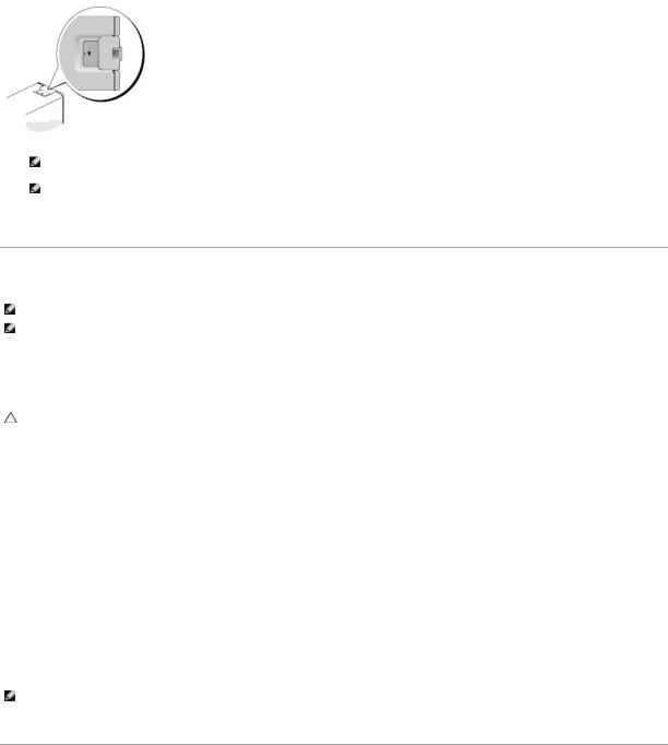
To remove the battery:
1.If you have not already done so, make a copy of your configuration information, found in system setup.
2.Follow the procedures in Working on Your Computer.
3.Remove the computer cover.
4.Locate the battery socket.
CAUTION: If you pry the battery out of its socket with a blunt object, be careful not to touch the system board with the object. Ensure that the object is inserted between the battery and the socket before you attempt to pry out the battery. Otherwise, you may damage the system board by prying off the socket or by breaking circuit traces on the system board.
CAUTION: To avoid damage to the battery connector, you must firmly support the connector while removing the battery.
5.Remove the system battery.
a.Support the battery connector by pressing down firmly on the positive side of the connector.
b.While supporting the battery connector, press the battery tab away from the positive side of the connector and pry the battery it up out of the securing tabs at the negative side of the connector.
1 system battery |
2 positive side of battery connector |
3battery socket tab 4 battery socket
6.Install the new system battery.
a.Support the battery connector by pressing down firmly on the positive side of the connector.
b.Hold the battery with the "+" facing up, and slide it under the securing tabs at the positive side of the connector.
c.Press the battery straight down into the connector until it snaps into place.
7.Replace the computer cover (see Replacing the Computer Cover).
8.Enter system setup (see Entering System Setup) and restore the settings you recorded in step 1.
9.Properly dispose of the old battery as described in the safety instructions that ship with your computer.
Back to Contents Page

Back to Contents Page
Working on Your Computer
Dell™ OptiPlex™ 760 Service Manual
Recommended Tools
Before Working on Your Computer
After Working on Your Computer
This document provides procedures for removing and installing the components in your computer. Unless otherwise noted, each procedure assumes that:
•You have performed the steps in this section.
•You have read the safety information that shipped with your computer.
•When replacing a component, you have already removed the original, if installed.
NOTE: The color of your computer and certain components may appear differently than shown in this document.
Recommended Tools
The procedures in this document may require the following tools:
•Small flat-blade screwdriver
•Phillips screwdriver
•Small plastic scribe
•Flash BIOS update (see the Dell Support website at support.dell.com)
Before Working on Your Computer
Use the following safety guidelines to help protect your computer from potential damage and to help ensure your own personal safety.
WARNING: Before working inside your computer, read the safety information that shipped with your computer. For additional safety best practices information, see the Regulatory Compliance Homepage at www.dell.com/regulatory_compliance.
CAUTION: Only a certified service technician should perform repairs on your computer. Damage due to servicing that is not authorized by Dell is not covered by your warranty.
CAUTION: When you disconnect a cable, pull on its connector or on its pull-tab, not on the cable itself. Some cables have connectors with locking tabs; if you are disconnecting this type of cable, press in on the locking tabs before you disconnect the cable. As you pull connectors apart, keep them evenly aligned to avoid bending any connector pins. Also, before you connect a cable, ensure that both connectors are correctly oriented and aligned.
CAUTION: To avoid damaging the computer, perform the following steps before you begin working inside the computer.
1.Ensure that the work surface is flat and clean to prevent the computer cover from being scratched.
2.Turn off your computer (see Turning Off Your Computer).
CAUTION: To disconnect a network cable, first unplug the cable from your computer and then unplug the cable from the network device.
3.Disconnect all telephone or network cables from the computer.
4.Disconnect your computer and all attached devices from their electrical outlets.
5.Press and hold the power button while the system is unplugged to ground the system board.
CAUTION: Before touching anything inside your computer, ground yourself by touching an unpainted metal surface, such as the metal at the back of the computer. While you work, periodically touch an unpainted metal surface to dissipate static electricity, which could harm internal components.
Turning Off Your Computer
CAUTION: To avoid losing data, save and close all open files and exit all open programs before you turn off your computer.

1.Shut down the operating system.
2.Ensure that the computer and all attached devices are turned off. If your computer and attached devices did not automatically turn off when you shut down your operating system, press and hold the power button for about 4 seconds to turn them off.
After Working on Your Computer
After you have completed any replacement procedures, ensure that you connect any external devices, cards, cables, and so on, before turning on your computer.
1.Replace the computer cover (see Replacing the Computer Cover).
2.Connect any telephone or network cables to your computer.
CAUTION: To connect a network cable, first plug the cable into the network device and then plug it into the computer.
3.Connect your computer and all attached devices to their electrical outlets.
4.Turn on your computer.
5.Verify that the computer works correctly by running the Dell Diagnostics (seeDell Diagnostics).
Back to Contents Page

Dell™ OptiPlex™ 760 Service Manual
Desktop Computer
About Your Computer |
Removing and Replacing Parts |
Inside Your Computer |
Working on Your Computer |
System Setup |
Removing the Computer Cover |
Advanced Features |
Chassis Intrusion Switch |
Troubleshooting |
Cards |
Getting Help |
Drives |
Glossary |
Heat Sink Assembly |
|
Processor |
|
System Fan |
|
I/O Panel |
|
Power Supply |
|
Speakers |
|
Memory |
|
Battery |
|
Replacing the System Board |
|
Replacing the Computer Cover |
|
|
Notes, Cautions, and Warnings
NOTE: A NOTE indicates important information that helps you make better use of your computer.
CAUTION: A CAUTION indicates potential damage to hardware or loss of data if instructions are not followed.
WARNING: A WARNING indicates a potential for property damage, personal injury, or death.
If you purchased a Dell™ n Series computer, any references in this document to Microsoft® Windows® operating systems are not applicable.
Information in this document is subject to change without notice.
©2008-2009 Dell Inc. All rights reserved.
Reproduction in any manner whatsoever without the written permission of Dell Inc. is strictly forbidden.
Trademarks used in this text: Dell, the DELL logo, OptiPlex, TravelLite, OpenManage, and StrikeZone are trademarks of Dell Inc.; Intel and SpeedStep are registered trademarks of Intel Corporation in the U.S and other countries; Microsoft, Windows, Windows Vista, and the Windows Start button are either registered trademarks or trademarks of Microsoft Corporation in the United States and/or other countries; Computrace is a registered trademark of Absolute Software Corp.; Citrix is a registered trademarks of Citrix Systems, Inc. and/or one or more of its subsidiaries, and may be registered in the United States Patent and Trademark Office and in other countries.; Bluetooth is a trademark owned by Bluetooth SIG, Inc. and is used by Dell Inc. under license.; ENERGY STAR is a registered trademark of the U.S. Environmental Protection Agency. As an ENERGY STAR partner, Dell Inc. has determined that this product meets the ENERGY STAR guidelines for energy efficiency.
Models: DCTR, DCNE, DCSM, and DCCY
February 2009 Rev. A01
Back to Contents Page
Back to Contents Page
Dell™ OptiPlex™ 760 Service Manual
Cards
Cards
WARNING: Before working inside your computer, read the safety information that shipped with your computer. For additional safety best practices information, see the Regulatory Compliance Homepage at www.dell.com/regulatory_compliance.
CAUTION: To prevent static damage to components inside your computer, discharge static electricity from your body before you touch any of your computer's electronic components. You can do so by touching an unpainted metal surface on the computer chassis.
CAUTION: Installing filler brackets over empty card-slot openings is necessary to maintain FCC certification of the computer. The brackets keep dust and dirt out of your computer and maintains the airflow that cools your computer.
Your Dell™ computer provides the following connectors on the system board for PCI and PCI Express cards:
•Two connectors for low-profile PCI cards
•One connector for a low-profile PCI Express x16 card
NOTE: Your Dell computer includes only PCI and PCI Express card connectors. ISA cards are not supported.
PCI Cards
Installing a PCI Card
If you are replacing a PCI card, remove the current driver for the card from the operating system. See the documentation that came with the card for information.
1.Follow the procedures in Working on Your Computer.
2.Remove the computer cover (see Removing the Computer Cover).
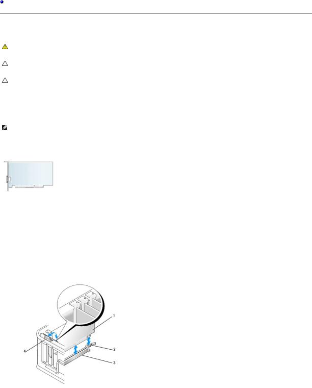
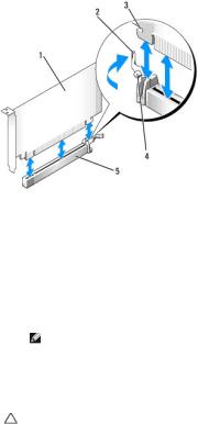
3.Gently lift the release tab on the card-retention latch all the way up.
1 |
card |
2 |
retention latch |
|
|
|
|
3 |
system board connector |
4 |
release tab |
|
|
|
|
4.If you are installing a card in an empty card connector on the system board, remove the filler bracket to create a card-slot opening at the back of the computer. Then continue with step 6.
5.If you are installing a card to replace one already installed in the computer, remove the installed card (see Removing a PCI Card).
6.Prepare the card for installation.
NOTE: See the documentation that came with the card for information on configuring the card, making internal connections, or customizing it for your computer.
1 |
release tab on card-retention latch |
2 |
card |
3 |
card-edge connector |
4 |
card connector |
|
|
|
|
WARNING: Some network adapters automatically start the computer when they are connected to a network. To guard against electrical shock, be sure to unplug your computer from its electrical outlet before installing any cards.
7.If you are installing a PCI Express x16 card, hold the securing-tab release lever away from the card connector as you insert the new card into the connector slot.
8.Place the card in the connector and press down firmly. Using the following illustration as a guide, ensure that the card is fully seated in the slot.
1 |
card fully seated |
2 |
card not fully seated |
|
|
|
|
3 |
bracket within slot |
4 |
bracket caught outside of slot |
|
|
|
|
NOTE: If you are installing a PCI Express x16 card, ensure that the securing tab on the connector's release lever fits into the notch on the front end of the card.
9. Gently rotate the release tab downward to move the card-retention latch into place to secure the cards.
CAUTION: Do not route card cables over or behind the cards. Cables routed over the cards can prevent the computer cover from closing properly or cause damage to the equipment.
10. Connect any cables that should be attached to the card.
11. Replace the computer cover (see Replacing the Computer Cover), reconnect the computer and devices to electrical outlets, and then turn them on.
CAUTION: To connect a network cable, first plug the cable into the network wall jack and then plug it into the computer.
12.If you installed a sound card:
a.Enter system setup, select System Configuration® Miscellaneous Devices, and change the Audio setting to Disabled. (See Entering System Setup).
b.Connect external audio devices to the sound card's connectors. Do not connect external audio devices to the microphone, speaker/headphone, or line-in connectors on the back panel of the computer.
CAUTION: If you disable the integrated network adapter, you will not have AMT functionality.
13.If you installed a network adapter card and want to turn off the integrated network adapter:
a.Enter system setup, select System Configuration® Integrated NIC, and change the setting to Disabled (see Entering System Setup).
b.Connect the network cable to the network adapter card's connectors. Do not connect the network cable to the integrated network connector on the back panel of the computer.
14.Install any drivers required for the card as described in the card documentation.
Removing a PCI Card
1.Follow the procedures in Working on Your Computer.
2.Remove the computer cover (see Removing the Computer Cover).
3.Gently rotate lift the release tab on the card-retention latch.
1 |
card |
2 |
card-retention latch |
3 |
system board connector |
4 |
card insert |
5release tab
4.If necessary, disconnect any cables connected to the card.
5.If you are replacing a PCI Express x16 card, remove the installed card by gently pulling the release lever away from the card until you release the securing tab from the dent in the card.
1 |
PCI Express x16 card |
2 |
release lever |
|
|
|
|
3 |
securing slot (not all cards) |
4 |
securing tab |
|
|
|
|
5 |
PCI Express x16 card connector |
|
|
|
|
|
|
6.Grasp the card by its top corners, and ease it out of its connector.
7.If you are removing the card permanently, install a filler bracket in the empty card-slot opening.
NOTE: Installing filler brackets over empty card-slot openings is necessary to maintain FCC certification of the computer. The brackets keep dust and dirt out of your computer and maintain the airflow that cools your computer.
8. Rotate the release tab downward to snap the card-retention latch into place.
CAUTION: To connect a network cable, first plug the cable into the network wall jack and then plug it into the computer.
9.Replace the computer cover (see Replacing the Computer Cover), reconnect the computer and devices to electrical outlets, and then turn them on.
10.Uninstall the card's driver. See the documentation that came with the card for instructions.
11.If you removed a sound card:
a.Enter system setup, select System Configuration® Miscellaneous Devices, and change the Audio setting to Enabled (see Entering System Setup).
b.Connect external audio devices to the sound card's connectors. Do not connect external audio devices to the microphone, speaker/headphone, or line-in connectors on the back panel of the computer.
12.If you removed a network adapter card and want to turn on the integrated network adapter:
a.Enter system setup, select System Configuration® Integrated NIC, and change the setting to Enabled (see Entering System Setup).
b.Connect the network cable to the integrated the back panel of the computer.
Removing a PCI Card From the Riser-Card Cage
1.Follow the procedures in Working on Your Computer.
2.Remove the computer cover (see Removing the Computer Cover).
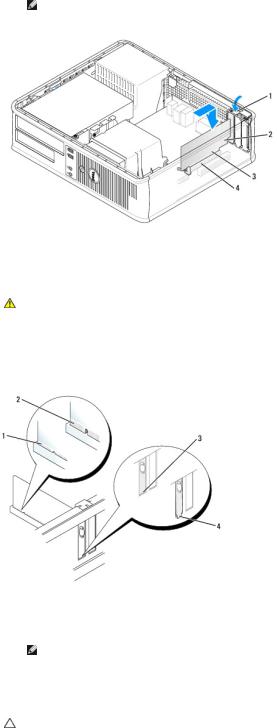
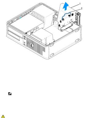
3.Remove the riser-card cage:
a.Check any cables connected to cards through the back panel openings. Disconnect any cables that will not reach the riser-card cage once they are removed from the computer.
b.Gently pull on the handle and lift the riser-card cage up and away from the computer.

1 |
riser-card cage |
2 |
handle |
|
|
|
|
4.Press in on the tab to raise the card-retention latch.
5.If necessary, disconnect any cables connected to the card.
6.Grasp the card by its top corners, and ease it out of its connector.
7.If you are removing the card permanently, install a filler bracket in the empty card-slot opening.
NOTE: Installing filler brackets over empty card-slot openings is necessary to maintain FCC certification of the computer. The brackets keep dust and dirt out of your computer and maintain the airflow that cools your computer.
8.Lower the card-retention latch and press it into place.
9.Replace the riser-card cage:
a.Align the tabs in the side of the riser-card cage with the slots on the side of the computer, and slide the riser-card cage down into place.
b.Ensure that the riser cards are fully seated in the connectors on the system board.
1 |
riser-card cage |
2 |
slots |
3 |
riser cards |
4 |
system board connectors |
|
|
|
|
10.Replace the computer cover (see Replacing the Computer Cover), reconnect the computer and devices to electrical outlets, and then turn them on.
11.Uninstall the card's driver. See the documentation that came with the card for instructions.
12.If you removed a sound card:
a.Enter system setup, select System Configuration® Miscellaneous Devices, and change the Audio setting to Enabled. (See Entering System Setup).
b.Connect external audio devices to the sound card's connectors. Do not connect external audio devices to the microphone, speaker/headphone, or line-in connectors on the back panel of the computer.
13.If you removed a network adapter card and want to turn on the integrated network adapter:
a.Enter system setup, select System Configuration® Integrated NIC, and change the setting to Enabled. (See Entering System Setup).
b.Connect the network cable to the integrated the back panel of the computer.
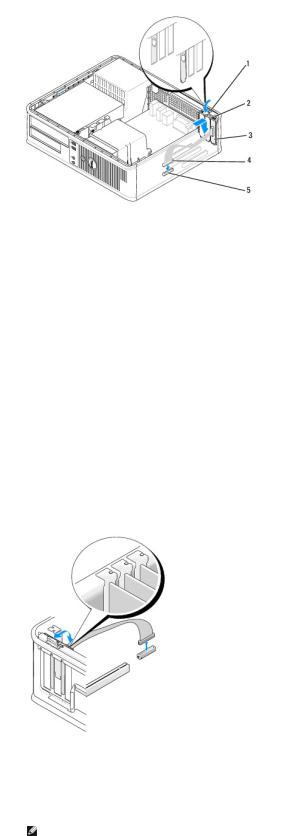
Installing a PCI Card in the Riser-Card Cage
1.Follow the procedures in Working on Your Computer.
2.Remove the computer cover (see Removing the Computer Cover).
3.If applicable, remove the card installed in the SLOT2 connector on the system board.
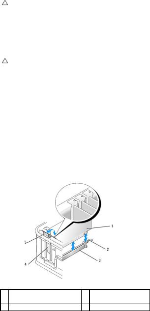
4.Remove the riser-card cage:
a.Check any cables connected to cards through the back panel openings. Disconnect any cables that will not reach the riser-card cage once they are removed from the computer.
b.Gently pull on the handle and lift the riser-card cage up and away from the computer.
1 |
riser-card cage |
2 |
handle |
|
|
|
|
5.If you are installing a new card, remove the filler bracket to create an empty card-slot opening.
If you are replacing a card that is already installed in the computer, remove the card. If necessary, disconnect any cables connected to the card. Grasp the card by its corners, and ease it out of its connector.
NOTE: See the documentation that came with the card for information on configuring the card, making internal connections, or customizing it for your computer.
6. Prepare the new card for installation.
WARNING: Some network adapters automatically start the computer when they are connected to a network. To guard against electrical shock, be sure to unplug your computer from its electrical outlet before installing any cards.
7. Press the release tab to raise the card-retention latch.
1 |
release tab |
2 |
card-retention latch |
|
|
|
|
3 |
card |
4 |
card-edge connector |
|
|
|
|
5 |
card connector |
|
|
|
|
|
|
8.Insert the card firmly into the card connector on the riser-card cage.
9.Lower the card-retention latch and press it into place, securing the card(s) in the computer.
10.Replace the riser-card cage:
a.Align the tabs in the side of the riser-card cage with the slots on the side of the computer, and slide the riser-card cage down into place.
b.Ensure that the riser cards are fully seated in the connectors on the system board.
1 |
riser-card cage |
2 |
slots |
|
|
|
|
3 |
riser cards |
4 |
system board connectors |
|
|
|
|
11.Reconnect any cables that you removed in step 4.
12.Connect any cables that should be attached to the card.
CAUTION: Do not route card cables over or behind the cards. Cables routed over the cards can prevent the computer cover from closing properly or cause damage to the equipment.
13.Replace the computer cover (see Replacing the Computer Cover), reconnect the computer and devices to electrical outlets, and then turn them on.
14.If you installed a sound card:
a. Enter system setup, select System Configuration® Miscellaneous Devices, and change the Audio setting to Disabled (see Entering System Setup).
b.Connect external audio devices to the sound card's connectors. Do not connect external audio devices to the microphone, speaker/headphone, or line-in connectors on the back panel of the computer.
15.If you installed a network adapter card and want to turn off the integrated network adapter:
a.Enter system setup, select System Configuration® Integrated NIC, and change the setting to Disabled. (See Entering System Setup).
b.Connect the network cable to the network adapter card's connectors. Do not connect the network cable to the integrated network connector on the back panel of the computer.
CAUTION: If you disable the integrated network adapter, you will not have AMT functionality.
16. Install any drivers required for the card as described in the card documentation.
PS/2 Serial Port Adapter
WARNING: Before working inside your computer, read the safety information that shipped with your computer. For additional safety best practices information, see the Regulatory Compliance Homepage at www.dell.com/regulatory_compliance.
CAUTION: To prevent static damage to components inside your computer, discharge static electricity from your body before you touch any of your computer's electronic components. You can do so by touching an unpainted metal surface on the computer chassis.
Installing a PS/2 Serial Port Adapter
1.Follow the procedures in Working on Your Computer.
2.Remove the computer cover (see Removing the Computer Cover).
3.Gently lift the release tab on the card retention latch from the inside to pivot the latch open. Pivot the latch until it snaps into the open position.
4.Remove the filler bracket (if applicable).
NOTE: See the documentation that came with the adapter for information on configuring the adapter, making internal connections, or customizing it for your computer.
5. Align the PS/2 serial-port adapter bracket in the retention slot and press down firmly. Ensure that the adapter is fully seated in the slot.
6. Before you close the card retention mechanism, ensure that:
•The tops of all cards and filler brackets are flush with the alignment bar.
•The notch in the top of the card or filler bracket fits around the alignment guide.
7.Secure the card(s) by closing the card retention latch and snapping it into place.
CAUTION: Do not route card cables over the cards. Cables routed over the cards can prevent the computer cover from closing properly or cause damage to the equipment.
1 |
release tab |
2 |
adapter retention latch |
|
|
|
|
3 |
PS/2 serial-port adapter bracket |
4 |
serial port adapter connector |
|
|
|
|
5 |
serial port adapter system board connector (SERIAL2) |
|
|
|
|
|
|
8.Connect the adapter cable to the PS/2 serial port adapter connector (SERIAL2) on the system board (see System Board Components).
 NOTE: See the documentation for the PS/2 serial port adapter for information about the cable connections.
9.Replace the computer cover (see Replacing the Computer Cover).
Removing a PS/2 Serial Port Adapter
1.Follow the procedures in Working on Your Computer.
2.Remove the computer cover (see Removing the Computer Cover).
3.Gently lift the release tab on the card retention latch from the inside to pivot the latch open. Pivot the latch until it snaps into the open position.
4.Disconnect the PS/2 serial-port cable from the system board (see System Board Components).
5.Ease the PS/2 serial-port adapter bracket out of its retention slot.
6.If you are removing the adapter permanently, install a filler bracket in the empty card-slot opening.
NOTE: Installing filler brackets over empty card-slot openings is necessary to maintain FCC certification of the computer. The brackets keep dust and dirt out of your computer and maintain the airflow that cools your computer.
7. Before you close the card retention mechanism, ensure that:
•The tops of all cards and filler brackets are flush with the alignment bar.
•The notch in the top of the card or filler bracket fits around the alignment guide.
8.Secure any remaining card(s) by closing the card retention latch and snapping it into place.
9.Replace the computer cover (see Replacing the Computer Cover).
Installing a PS/2 Serial Port Adapter in the Riser-Card Cage
1.Follow the procedures in Working on Your Computer.
2.Remove the computer cover (see Removing the Computer Cover).
3.Remove the riser-card cage:
a.Check any cables connected to cards through the back panel openings. Disconnect any cables that will not reach the riser-card cage once they are removed from the computer.
b.Rotate the riser-card cage handle up and gently pull on the handle to lift the riser-card cage up and away from the computer.
1 |
riser-card cage |
2 |
handle |
3riser cards (2)
4.Gently lift the release tab on the card retention latch from the inside to pivot the latch open. Pivot the latch until it snaps into the open position.
5.If you are installing a new PS/2 serial port adapter, remove the filler bracket to create an empty card-slot opening.
6.If you are replacing a PS/2 adapter that is already installed in the computer, remove the adapter.
7.If necessary, disconnect any cables connected to the adapter.
WARNING: To guard against electrical shock, be sure to unplug your computer from its electrical outlet before installing any cards or adapters.
8.Align the PS/2 serial-port adapter bracket in the retention slot and press down firmly. Ensure that the adapter is fully seated in the slot.
9.Before you close the card retention mechanism, ensure that:
•The tops of all cards and filler brackets are flush with the alignment bar.
•The notch in the top of the card or filler bracket fits around the alignment guide.
10.Secure the card(s) by closing the card retention latch and snapping it into place.
CAUTION: Do not route card cables over the cards. Cables routed over the cards can prevent the computer cover from closing properly or cause damage to the equipment.
11. Connect the adapter cable to the PS/2 serial port adapter connector (PS2/SERIAL2) on the system board (see System Board Components).
12.Replace the riser-card cage:
a.Align the tabs in the side of the riser-card cage with the slots on the side of the computer, and slide the riser-card cage down into place.
b.Ensure that the riser-card connectors are fully seated in the connectors on the system board.
c.Rotate the riser-card cage handle to the down position.
13.Connect any disconnected cables.
14.Replace the computer cover (see Replacing the Computer Cover).
15.Install any drivers required for the PS/2 serial port adapter.
Removing a PS/2 Serial Port Adapter From the Riser-Card Cage
1.Follow the procedures in Working on Your Computer.
2.Remove the computer cover (see Removing the Computer Cover).
3.Remove the riser-card cage:
a.Check any cables connected to cards through the back panel openings. Disconnect any cables that will not reach the riser-card cage once they are removed from the computer.
b.Rotate the riser-card cage handle up and gently pull on the handle and lift the riser-card cage up and away from the computer.
1 |
riser-card cage |
2 |
handle |
3riser cards (2)
4.Gently lift the release tab on the card retention latch from the inside to pivot the latch open. Pivot the latch until it snaps into the open position.
5.Disconnect the PS/2 serial-port cable from the system board (see System Board Components).
6.Grasp the PS/2 serial-port adapter bracket by its top corners, and ease it out of its connector.
7.If you are removing the adapter permanently, install a filler bracket in the empty card-slot opening.
NOTE: Installing filler brackets over empty card-slot openings is necessary to maintain FCC certification of the computer. The brackets also keep dust and dirt out of your computer.
8. Before you close the card retention mechanism, ensure that:
•The tops of all cards and filler brackets are flush with the alignment bar.
•The notch in the top of the card or filler bracket fits around the alignment guide.
9.Secure the card(s) by closing the card retention latch and snapping it into place.
10.Replace the riser-card cage:
a.Align the tabs in the side of the riser-card cage with the slots on the side of the computer, and slide the riser-card cage down into place.
b.Ensure that the riser-card connectors are fully seated in the connectors on the system board.

c.Rotate the riser-card cage handle to the down position.
11.Replace the computer cover (see Replacing the Computer Cover).
12.Uninstall the adapter's driver. See the documentation that came with the adapter for instructions.
Back to Contents Page
Back to Contents Page
Dell™ OptiPlex™ 760 Service Manual
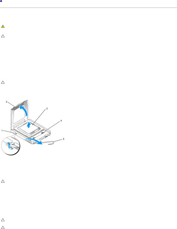
Processor
Processor
WARNING: Before working inside your computer, read the safety information that shipped with your computer. For additional safety best practices information, see the Regulatory Compliance Homepage at www.dell.com/regulatory_compliance.
CAUTION: To prevent static damage to components inside your computer, discharge static electricity from your body before you touch any of your computer's electronic components. You can do so by touching an unpainted metal surface on the computer chassis.
Removing the Processor
1.Follow the procedures in Working on Your Computer.
2.Remove the computer cover (see Removing the Computer Cover).
3.Remove the heat sink assembly (see Removing the Heat Sink Assembly).
CAUTION: Unless a new heat sink is required for the new processor, reuse the original heat sink assembly when you replace the processor.
4. Open the processor cover by sliding the release lever from under the center cover latch on the socket. Then pull the lever back to release the processor.
1 |
center cover latch |
2 |
processor cover |
|
|
|
|
3 |
processor |
4 |
socket |
5 |
release lever |
|
|
|
|
|
|
CAUTION: When replacing the processor, do not touch any of the pins inside the socket or allow any objects to fall on the pins in the socket.
5.Gently remove the processor from the socket.
Leave the release lever extended in the release position so that the socket is ready for the new processor.
Installing the Processor
CAUTION: Ground yourself by touching an unpainted metal surface on the back of the computer.
CAUTION: When replacing the processor, do not touch any of the pins inside the socket or allow any objects to fall on the pins in the socket.
1.Follow the procedures in Working on Your Computer.
2.Remove the computer cover (see Removing the Computer Cover).
3.Unpack the new processor, being careful not to touch the underside of the processor.
CAUTION: You must position the processor correctly in the socket to avoid permanent damage to the processor and the computer when you turn on the computer.
4.If the release lever on the socket is not fully extended, move it to that position.
5.Orient the front and rear alignment-notches on the processor with the front and rear alignment-notches on the socket.
6.Align the pin-1 corners of the processor and socket.
1 |
processor cover |
2 |
tab |
|
|
|
|
3 |
processor |
4 |
processor socket |
|
|
|
|
5 |
center cover latch |
6 |
release lever |
|
|
|
|
7 |
front alignment-notch |
8 |
socket and processor pin-1 indicator |
|
|
|
|
9 |
rear alignment-notch |
|
|
|
|
|
|
CAUTION: To avoid damage, ensure that the processor aligns properly with the socket, and do not use excessive force when you install the processor.
7.Set the processor lightly in the socket and ensure that the processor is positioned correctly.
8.When the processor is fully seated in the socket, close the processor cover.
Ensure that the tab on the processor cover is positioned underneath the center cover latch on the socket.
9.Pivot the socket release lever back toward the socket, and snap it into place to secure the processor.
10.Clean the thermal grease from the bottom of the heat sink.
CAUTION: Ensure that you apply new thermal grease. New thermal grease is critical for ensuring adequate thermal bonding, which is a requirement for optimal processor operation.
11.Apply the new thermal grease to the top of the processor.
12.Install the heat sink assembly (see Installing the Heat Sink Assembly).
13.Replace the computer cover (see Replacing the Computer Cover).
Back to Contents Page
Back to Contents Page
Dell™ OptiPlex™ 760 Service Manual
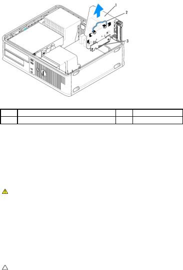
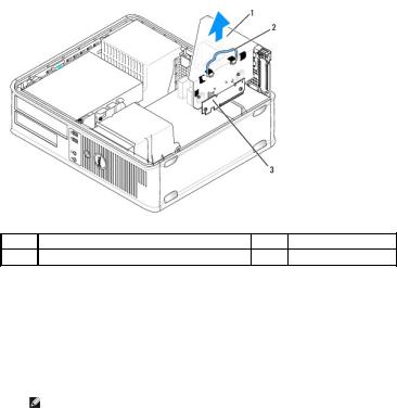
Chassis Intrusion Switch
Chassis Intrusion Switch
WARNING: Before working inside your computer, read the safety information that shipped with your computer. For additional safety best practices information, see the Regulatory Compliance Homepage at www.dell.com/regulatory_compliance.
NOTE: The chassis intrusion switch is standard on the ultra small form factor computer but is optional on mini tower, desktop, and small form factor computers; it may not be present on your computer.
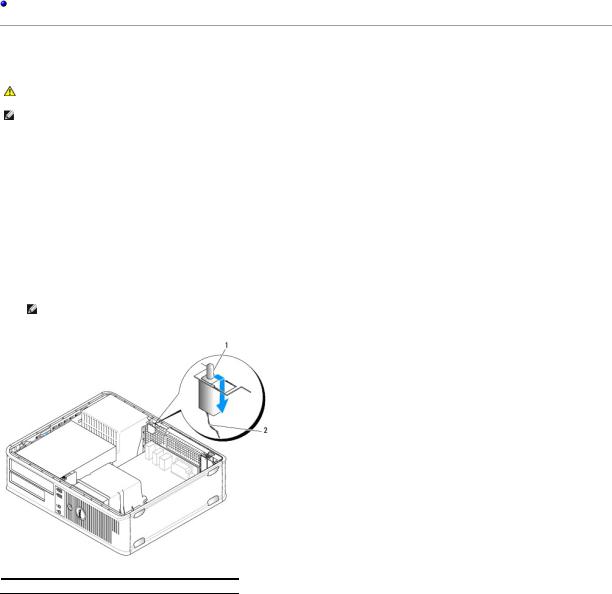
Removing the Chassis Intrusion Switch
1.Follow the procedures in Working on Your Computer.
2.Remove the computer cover (see Removing the Computer Cover).
3.Press the chassis intrusion switch cable connector release mechanism and pull the cable connector to disconnect the chassis intrusion switch cable from the system board.
4.Slide the chassis intrusion switch out of its slot in the metal bracket, and then push it down through the square hole in the bracket to remove the switch and its attached cable from the computer.
NOTE: You may feel a slight resistance as you slide the switch out of the slot.
 1
1  chassis intrusion switch
  2
2  chassis intrusion switch cable
Replacing the Chassis Intrusion Switch
1.Gently insert the switch from underneath the metal bracket into the square hole in the bracket, and then slide the chassis intrusion switch into its slot until it snaps securely into place.
2.Reconnect the cable to the system board.
3.Replace the computer cover (see Replacing the Computer Cover).
Resetting the Chassis Intrusion Detector
1. Turn on (or restart) your computer.
 Loading...