


 Loading...
Dell™ PowerConnect™ 34XX Systems
User’s Guide

Notes, Notices, and Cautions
NOTE: A NOTE indicates important information that helps you make better use of your computer.
NOTICE: A NOTICE indicates either potential damage to hardware or loss of data and tells you how to avoid the problem.
 CAUTION: A CAUTION indicates a potential for property damage, personal injury, or death.
____________________
Information in this document is subject to change without notice. © 2005 Dell Inc. All rights reserved.
Reproduction in any manner whatsoever without the written permission of Dell Inc. is strictly forbidden.
Trademarks used in this text: Dell, Dell OpenManage, the DELL logo, and PowerConnect are trademarks of Dell Inc. Microsoft and Windows are registered trademarks of Microsoft Corporation.
Other trademarks and trade names may be used in this document to refer to either the entities claiming the marks and names or their products. Dell Inc. disclaims any proprietary interest in trademarks and trade names other than its own.
May 2005 Rev A01

Contents
1 Introduction
System Description . . . . . . . . . . . . . . . . . . . . . . . . . . . . |
21 |
PowerConnect 3424 . . . . . . . . . . . . . . . . . . . . . . . . . . |
21 |
PowerConnect 3424P . . . . . . . . . . . . . . . . . . . . . . . . . |
21 |
PowerConnect 3448 . . . . . . . . . . . . . . . . . . . . . . . . . . |
22 |
PowerConnect 3448P . . . . . . . . . . . . . . . . . . . . . . . . . |
22 |
Stacking Overview . . . . . . . . . . . . . . . . . . . . . . . . . . . . |
22 |
Understanding the Stack Topology . . . . . . . . . . . . . . . . . . . |
23 |
Stacking Failover Topology . . . . . . . . . . . . . . . . . . . . . . |
23 |
Stacking Members and Unit ID. . . . . . . . . . . . . . . . . . . . . |
23 |
Removing and Replacing Stacking Members . . . . . . . . . . . . . . |
24 |
Exchanging Stacking Members . . . . . . . . . . . . . . . . . . . . |
25 |
Switching from the Stack Master to the Backup Stack Master. . . . . . 27 |
|
Features Overview. . . . . . . . . . . . . . . . . . . . . . . . . . . . . |
28 |
Power over Ethernet . . . . . . . . . . . . . . . . . . . . . . . . . |
28 |
Head of Line Blocking . . . . . . . . . . . . . . . . . . . . . . . . . |
28 |
Flow Control Support (IEEE 802.3X) . . . . . . . . . . . . . . . . . . . |
28 |
Back Pressure Support . . . . . . . . . . . . . . . . . . . . . . . . |
28 |
Virtual Cable Testing (VCT). . . . . . . . . . . . . . . . . . . . . . . |
28 |
MDI/MDIX Support . . . . . . . . . . . . . . . . . . . . . . . . . . |
29 |
Auto Negotiation . . . . . . . . . . . . . . . . . . . . . . . . . . . |
29 |
MAC Address Supported Features . . . . . . . . . . . . . . . . . . . |
29 |
Layer 2 Features . . . . . . . . . . . . . . . . . . . . . . . . . . . |
30 |
VLAN Supported Features . . . . . . . . . . . . . . . . . . . . . . . |
31 |
Spanning Tree Protocol Features. . . . . . . . . . . . . . . . . . . . |
31 |
Link Aggregation . . . . . . . . . . . . . . . . . . . . . . . . . . . |
32 |
Quality of Service Features . . . . . . . . . . . . . . . . . . . . . . |
33 |
Device Management Features . . . . . . . . . . . . . . . . . . . . . |
33 |
Security Features . . . . . . . . . . . . . . . . . . . . . . . . . . . |
35 |
Additional CLI Documentation . . . . . . . . . . . . . . . . . . . . . . . |
36 |
Contents 3

2 Hardware Description
Port Description . . . . . . . . . . . . . . . . . . . . . . . . . . . . . . |
37 |
PowerConnect 3424 Port Description. . . . . . . . . . . . . . . . . . |
37 |
PowerConnect 3448 Port Description. . . . . . . . . . . . . . . . . . |
38 |
SFP Ports . . . . . . . . . . . . . . . . . . . . . . . . . . . . . . . |
39 |
RS-232 Console Port. . . . . . . . . . . . . . . . . . . . . . . . . . |
39 |
Physical Dimensions. . . . . . . . . . . . . . . . . . . . . . . . . . . . |
40 |
LED Definitions . . . . . . . . . . . . . . . . . . . . . . . . . . . . . . |
40 |
Gigabit Port LEDs . . . . . . . . . . . . . . . . . . . . . . . . . . . |
43 |
System LEDs . . . . . . . . . . . . . . . . . . . . . . . . . . . . . |
44 |
Power Supplies . . . . . . . . . . . . . . . . . . . . . . . . . . . . |
45 |
Stack ID Button . . . . . . . . . . . . . . . . . . . . . . . . . . . . |
47 |
Reset Button . . . . . . . . . . . . . . . . . . . . . . . . . . . . . |
47 |
Ventilation System. . . . . . . . . . . . . . . . . . . . . . . . . . . |
47 |
3 Installing the PowerConnect 3424/P and
PowerConnect 3448/P
Site Preparation . . . . . . . . . . . . . . . . . . . . . . . . . . . . . . |
49 |
Unpacking. . . . . . . . . . . . . . . . . . . . . . . . . . . . . . . . . |
49 |
Package Contents. . . . . . . . . . . . . . . . . . . . . . . . . . . |
49 |
Unpacking the Device . . . . . . . . . . . . . . . . . . . . . . . . . |
50 |
Mounting the Device. . . . . . . . . . . . . . . . . . . . . . . . . . . . |
50 |
Installing in a Rack . . . . . . . . . . . . . . . . . . . . . . . . . . |
50 |
Installing on a Flat Surface . . . . . . . . . . . . . . . . . . . . . . |
51 |
Installing the Device on a Wall . . . . . . . . . . . . . . . . . . . . . |
52 |
Connecting to a Terminal . . . . . . . . . . . . . . . . . . . . . . . |
53 |
Connecting a Device to a Power Supply . . . . . . . . . . . . . . . . . . |
54 |
Installing a Stack . . . . . . . . . . . . . . . . . . . . . . . . . . . . . |
54 |
Overview . . . . . . . . . . . . . . . . . . . . . . . . . . . . . . . |
54 |
Stacking PowerConnect 3400 Series Switches . . . . . . . . . . . . . |
54 |
Unit ID Selection Process . . . . . . . . . . . . . . . . . . . . . . . |
56 |
Starting and Configuring the Device . . . . . . . . . . . . . . . . . . . . |
57 |
Connecting to the Device . . . . . . . . . . . . . . . . . . . . . . . |
57 |
4 Contents

4 Configuring PowerConnect 3424/P and 3448/P
Configuration Procedures . . . . . . . . . . . . . . . . . . . . . . . . . |
59 |
Booting the Switch . . . . . . . . . . . . . . . . . . . . . . . . . . |
60 |
Initial Configuration . . . . . . . . . . . . . . . . . . . . . . . . . . |
61 |
Advanced Configuration . . . . . . . . . . . . . . . . . . . . . . . . . . |
65 |
Retrieving an IP Address From a DHCP Server . . . . . . . . . . . . . |
65 |
Receiving an IP Address From a BOOTP Server . . . . . . . . . . . . . |
66 |
Security Management and Password Configuration. . . . . . . . . . . |
67 |
Startup Procedures . . . . . . . . . . . . . . . . . . . . . . . . . . . . |
70 |
Startup Menu Procedures . . . . . . . . . . . . . . . . . . . . . . . |
70 |
Software Download Through TFTP Server . . . . . . . . . . . . . . . |
73 |
Port Default Settings . . . . . . . . . . . . . . . . . . . . . . . . . . . . |
76 |
Auto-Negotiation . . . . . . . . . . . . . . . . . . . . . . . . . . . |
76 |
MDI/MDIX . . . . . . . . . . . . . . . . . . . . . . . . . . . . . . |
76 |
Flow Control . . . . . . . . . . . . . . . . . . . . . . . . . . . . . |
76 |
Back Pressure . . . . . . . . . . . . . . . . . . . . . . . . . . . . |
76 |
Switching Port Default Settings . . . . . . . . . . . . . . . . . . . . |
77 |
5 Using Dell OpenManage Switch Administrator
Starting the Application . . . . . . . . . . . . . . . . . . . . . . . . . . |
79 |
Understanding the Interface . . . . . . . . . . . . . . . . . . . . . . . . |
79 |
Device Representation . . . . . . . . . . . . . . . . . . . . . . . . |
81 |
Using the Switch Administrator Buttons . . . . . . . . . . . . . . . . . . |
82 |
Information Buttons . . . . . . . . . . . . . . . . . . . . . . . . . . |
82 |
Device Management Buttons . . . . . . . . . . . . . . . . . . . . . |
82 |
Field Definitions . . . . . . . . . . . . . . . . . . . . . . . . . . . . . . |
83 |
Accessing the Device Through the CLI . . . . . . . . . . . . . . . . . . . |
83 |
Terminal Connection . . . . . . . . . . . . . . . . . . . . . . . . . |
83 |
Telnet Connection . . . . . . . . . . . . . . . . . . . . . . . . . . . |
84 |
Using the CLI . . . . . . . . . . . . . . . . . . . . . . . . . . . . . . . |
84 |
Command Mode Overview. . . . . . . . . . . . . . . . . . . . . . . |
84 |
User EXEC Mode . . . . . . . . . . . . . . . . . . . . . . . . . . . |
85 |
Privileged EXEC Mode. . . . . . . . . . . . . . . . . . . . . . . . . |
85 |
Global Configuration Mode . . . . . . . . . . . . . . . . . . . . . . |
86 |
Contents 5

6 Configuring System Information
Defining General Switch Information . . . . . . . . . . . . . . . . . . . . |
88 |
Viewing Switch Asset Information . . . . . . . . . . . . . . . . . . . |
88 |
Defining System Time Settings . . . . . . . . . . . . . . . . . . . . . |
93 |
Viewing System Health Information . . . . . . . . . . . . . . . . . . |
98 |
Managing Power over Ethernet . . . . . . . . . . . . . . . . . . . |
101 |
Viewing Version Information . . . . . . . . . . . . . . . . . . . . . |
106 |
Managing Stack Members. . . . . . . . . . . . . . . . . . . . . . |
107 |
Resetting the Device . . . . . . . . . . . . . . . . . . . . . . . . |
109 |
Configuring SNTP Settings . . . . . . . . . . . . . . . . . . . . . . . . |
110 |
Defining SNTP Global Parameters . . . . . . . . . . . . . . . . . . |
112 |
Defining SNTP Authentication Methods . . . . . . . . . . . . . . . |
114 |
Defining SNTP Servers . . . . . . . . . . . . . . . . . . . . . . . |
116 |
Defining SNTP Interfaces . . . . . . . . . . . . . . . . . . . . . . |
120 |
Managing Logs . . . . . . . . . . . . . . . . . . . . . . . . . . . . . |
122 |
Defining Global Log Parameters . . . . . . . . . . . . . . . . . . . |
122 |
Viewing the RAM Log Table . . . . . . . . . . . . . . . . . . . . . |
126 |
Viewing the Log File Table . . . . . . . . . . . . . . . . . . . . . . |
128 |
Viewing the Device Login History . . . . . . . . . . . . . . . . . . |
130 |
Modifying Remote Log Server Definitions. . . . . . . . . . . . . . . |
132 |
Defining IP Addressing. . . . . . . . . . . . . . . . . . . . . . . . . . |
135 |
Defining Default Gateways. . . . . . . . . . . . . . . . . . . . . . |
135 |
Defining IP Interfaces . . . . . . . . . . . . . . . . . . . . . . . . |
137 |
Defining DHCP IP Interface Parameters . . . . . . . . . . . . . . . |
140 |
Configuring Domain Name Systems . . . . . . . . . . . . . . . . . |
142 |
Defining Default Domains . . . . . . . . . . . . . . . . . . . . . . |
145 |
Mapping Domain Host. . . . . . . . . . . . . . . . . . . . . . . . |
146 |
Defining ARP Settings . . . . . . . . . . . . . . . . . . . . . . . . |
149 |
Running Cable Diagnostics. . . . . . . . . . . . . . . . . . . . . . . . |
152 |
Viewing Copper Cable Diagnostics . . . . . . . . . . . . . . . . . . |
152 |
Viewing Optical Transceiver Diagnostics . . . . . . . . . . . . . . . |
154 |
Managing Switch Security . . . . . . . . . . . . . . . . . . . . . . . . |
156 |
Defining Access Profiles . . . . . . . . . . . . . . . . . . . . . . |
156 |
Defining Authentication Profiles . . . . . . . . . . . . . . . . . . . |
163 |
Selecting Authentication Profiles . . . . . . . . . . . . . . . . . . |
166 |
Managing Passwords . . . . . . . . . . . . . . . . . . . . . . . . |
170 |
Defining the Local User Databases. . . . . . . . . . . . . . . . . . |
173 |
6 Contents

Defining Line Passwords . . . . . . . . . . . . . . . . . . . . . . |
177 |
Defining Enable Passwords . . . . . . . . . . . . . . . . . . . . . |
179 |
Defining TACACS+ Settings . . . . . . . . . . . . . . . . . . . . . |
180 |
Configuring RADIUS Settings . . . . . . . . . . . . . . . . . . . . |
184 |
Defining SNMP Parameters . . . . . . . . . . . . . . . . . . . . . . . |
189 |
Defining SNMP Global Parameters. . . . . . . . . . . . . . . . . . |
190 |
Defining SNMP View Settings . . . . . . . . . . . . . . . . . . . . |
193 |
Defining SNMP Access Control . . . . . . . . . . . . . . . . . . . |
196 |
Assigning SNMP User Security . . . . . . . . . . . . . . . . . . . |
199 |
Defining SNMP Communities . . . . . . . . . . . . . . . . . . . . |
202 |
Defining SNMP Notification Filters . . . . . . . . . . . . . . . . . . |
205 |
Defining SNMP Notification Recipients. . . . . . . . . . . . . . . . |
208 |
Managing Files . . . . . . . . . . . . . . . . . . . . . . . . . . . . . |
212 |
Management File Overview . . . . . . . . . . . . . . . . . . . . . |
212 |
Downloading Files. . . . . . . . . . . . . . . . . . . . . . . . . . |
213 |
Uploading Files . . . . . . . . . . . . . . . . . . . . . . . . . . . |
215 |
Activating Image Files . . . . . . . . . . . . . . . . . . . . . . . . |
218 |
Copying Files . . . . . . . . . . . . . . . . . . . . . . . . . . . . |
219 |
Managing Device Files . . . . . . . . . . . . . . . . . . . . . . . |
221 |
Configuring General Settings. . . . . . . . . . . . . . . . . . . . . . . |
223 |
7 Configuring Switch Information
Configuring Network Security . . . . . . . . . . . . . . . . . . . . . . |
225 |
Port Based Authentication. . . . . . . . . . . . . . . . . . . . . . |
225 |
Configuring Port Based Authentication . . . . . . . . . . . . . . . . . . |
227 |
Configuring Advanced Port Based Authentication. . . . . . . . . . . |
231 |
Authenticating Users . . . . . . . . . . . . . . . . . . . . . . . . |
235 |
Configuring Port Security . . . . . . . . . . . . . . . . . . . . . . |
237 |
Defining MAC Based ACLs. . . . . . . . . . . . . . . . . . . . . . |
241 |
Configuring ACL Binding. . . . . . . . . . . . . . . . . . . . . . . |
244 |
Configuring Ports . . . . . . . . . . . . . . . . . . . . . . . . . . . . |
246 |
Defining Port Configuration . . . . . . . . . . . . . . . . . . . . . |
246 |
Defining LAG Parameters . . . . . . . . . . . . . . . . . . . . . . |
252 |
Enabling Storm Control . . . . . . . . . . . . . . . . . . . . . . . |
257 |
Defining Port Mirroring Sessions. . . . . . . . . . . . . . . . . . . |
260 |
Contents 7

Configuring Address Tables . . . . . . . . . . . . . . . . . . . . . . . |
263 |
Defining Static Addresses . . . . . . . . . . . . . . . . . . . . . . |
263 |
Viewing Dynamic Addresses. . . . . . . . . . . . . . . . . . . . . |
267 |
Configuring GARP . . . . . . . . . . . . . . . . . . . . . . . . . . . . |
270 |
Defining GARP Timers . . . . . . . . . . . . . . . . . . . . . . . . |
270 |
Configuring the Spanning Tree Protocol . . . . . . . . . . . . . . . . . |
273 |
Defining STP Global Settings. . . . . . . . . . . . . . . . . . . . . |
274 |
Defining STP Port Settings. . . . . . . . . . . . . . . . . . . . . . |
280 |
Defining STP LAG Settings. . . . . . . . . . . . . . . . . . . . . . |
284 |
Defining Rapid Spanning Tree . . . . . . . . . . . . . . . . . . . . |
288 |
Configuring Multiple Spanning Tree . . . . . . . . . . . . . . . . . |
291 |
Defining MSTP Interface Settings . . . . . . . . . . . . . . . . . . |
295 |
Configuring VLANs. . . . . . . . . . . . . . . . . . . . . . . . . . . . |
299 |
Defining VLAN Membership . . . . . . . . . . . . . . . . . . . . . |
300 |
Defining VLAN Ports Settings . . . . . . . . . . . . . . . . . . . . |
305 |
Defining VLAN LAGs Settings . . . . . . . . . . . . . . . . . . . . |
307 |
Binding MAC Address to VLANs . . . . . . . . . . . . . . . . . . . |
310 |
Configuring GVRP Parameters . . . . . . . . . . . . . . . . . . . . |
312 |
Configuring Private VLANs. . . . . . . . . . . . . . . . . . . . . . |
315 |
Aggregating Ports . . . . . . . . . . . . . . . . . . . . . . . . . . . . |
319 |
Defining LACP Parameters. . . . . . . . . . . . . . . . . . . . . . |
319 |
Defining LACP Parameters. . . . . . . . . . . . . . . . . . . . . . |
320 |
Defining LAG Membership . . . . . . . . . . . . . . . . . . . . . . |
322 |
Multicast Forwarding Support . . . . . . . . . . . . . . . . . . . . . . |
324 |
Defining Multicast Global Parameters . . . . . . . . . . . . . . . . |
324 |
Adding Bridge Multicast Address Members . . . . . . . . . . . . . |
326 |
Assigning Multicast Forward All Parameters . . . . . . . . . . . . . |
331 |
IGMP Snooping . . . . . . . . . . . . . . . . . . . . . . . . . . . |
334 |
8 Viewing Statistics
Viewing Tables . . . . . . . . . . . . . . . . . . . . . . . . . . . . . |
337 |
Viewing Utilization Summary. . . . . . . . . . . . . . . . . . . . . |
337 |
Viewing Counter Summary. . . . . . . . . . . . . . . . . . . . . . |
338 |
Viewing Interface Statistics . . . . . . . . . . . . . . . . . . . . . |
340 |
Viewing Etherlike Statistics . . . . . . . . . . . . . . . . . . . . . |
343 |
Viewing GVRP Statistics . . . . . . . . . . . . . . . . . . . . . . . |
345 |
8 Contents

Viewing EAP Statistics . . . . . . . . . . . . . . . . . . . . . . . |
349 |
Viewing EAP Statistics Using the CLI Commands . . . . . . . . . . . |
350 |
Viewing RMON Statistics . . . . . . . . . . . . . . . . . . . . . . . . |
352 |
Viewing RMON Statistics Group . . . . . . . . . . . . . . . . . . . |
352 |
Viewing RMON History Control Statistics . . . . . . . . . . . . . . . |
354 |
Viewing the RMON History Table. . . . . . . . . . . . . . . . . . . |
356 |
Defining Device RMON Events . . . . . . . . . . . . . . . . . . . . |
360 |
Viewing the RMON Events Log . . . . . . . . . . . . . . . . . . . . |
362 |
Defining RMON Device Alarms. . . . . . . . . . . . . . . . . . . . |
363 |
Viewing Charts . . . . . . . . . . . . . . . . . . . . . . . . . . . . . |
367 |
Viewing Port Statistics . . . . . . . . . . . . . . . . . . . . . . . |
367 |
Viewing LAG Statistics . . . . . . . . . . . . . . . . . . . . . . . |
369 |
Viewing the CPU Utilization . . . . . . . . . . . . . . . . . . . . . |
371 |
9 Configuring Quality of Service
Quality of Service (QoS) Overview . . . . . . . . . . . . . . . . . . . . |
373 |
CoS Services . . . . . . . . . . . . . . . . . . . . . . . . . . . . |
374 |
Defining QoS Global Parameters . . . . . . . . . . . . . . . . . . . . . |
375 |
Configuring QoS Global Settings . . . . . . . . . . . . . . . . . . . |
375 |
Defining QoS Interface Settings . . . . . . . . . . . . . . . . . . . |
377 |
Mapping CoS Values to Queues . . . . . . . . . . . . . . . . . . . |
379 |
Mapping DSCP Values to Queues . . . . . . . . . . . . . . . . . . |
380 |
A Device Feature Interaction Information |
|
Glossary . . . . . . . . . . . . . . . . . . . . . . . . . . . . . . . . . |
387 |
Index . . . . . . . . . . . . . . . . . . . . . . . . . . . . . . . . . . . |
399 |
Contents 9

Figures
Figure 1-1. |
PowerConnect 3424 and PowerConnect 3424P . . . |
21 |
Figure 1-2. |
PowerConnect 3448 and PowerConnect 3448P . . . |
22 |
Figure 1-3. |
Stacking Ring Topology . . . . . . . . . . . . . . |
23 |
Figure 1-4. |
PowerConnect 3448/P replaces |
|
|
PowerConnect 3448/P . . . . . . . . . . . . . . . |
26 |
Figure 1-5. |
PowerConect 3424/P port replaces |
|
|
PowerConnect 3448/P port . . . . . . . . . . . . |
26 |
Figure 1-6. |
PowerConnect 3448/P port replaces |
|
|
PowerConect 3424/P Port . . . . . . . . . . . . . |
27 |
Figure 2-1. |
PowerConnect 3424 Front Panel . . . . . . . . . . |
37 |
Figure 2-2. |
PowerConnect 3424 Back Panel . . . . . . . . . . |
38 |
Figure 2-3. |
PowerConnect 3448 Front Panel . . . . . . . . . . |
38 |
Figure 2-4. |
PowerConnect 3448 Back Panel . . . . . . . . . . |
39 |
Figure 2-5. |
Console Port . . . . . . . . . . . . . . . . . . . |
39 |
Figure 2-6. |
RJ-45 Copper Based 10/100 BaseT LEDs . . . . . . |
40 |
Figure 2-7. |
RJ-45 1000 BaseT LED . . . . . . . . . . . . . . . |
41 |
Figure 2-8. |
SFP Port LEDs . . . . . . . . . . . . . . . . . . . |
43 |
Figure 2-9. |
System LEDs . . . . . . . . . . . . . . . . . . . |
44 |
Figure 2-10. |
Stacking LEDs . . . . . . . . . . . . . . . . . . |
45 |
Figure 2-11. |
Power Connection . . . . . . . . . . . . . . . . |
46 |
Figure 3-1. |
Bracket Installation for Rack Mounting . . . . . . . |
51 |
Figure 3-2. |
Bracket Installation for Mounting on a Wall . . . . . |
52 |
Figure 3-3. |
Mounting a Device on a Wall . . . . . . . . . . . |
53 |
Figure 3-4. |
Back-Panel Power Connector . . . . . . . . . . . |
54 |
Figure 3-5. |
Stacking Cable Diagram . . . . . . . . . . . . . . |
55 |
Figure 3-6. |
Stacking Configuration and Identification Panel . . . |
56 |
Figure 3-7. |
Connecting to PowerConnect 3400 Series |
|
|
Console Port . . . . . . . . . . . . . . . . . . . |
58 |
10 Contents
Figure 4-1. |
Installation and Configuration Flow . . . . . . . . . |
60 |
Figure 5-1. |
Switch Administrator Components . . . . . . . . . |
80 |
Figure 5-2. |
PowerConnect Device Port Indicators . . . . . . . |
81 |
Figure 6-1. |
System . . . . . . . . . . . . . . . . . . . . . . |
87 |
Figure 6-2. |
Asset . . . . . . . . . . . . . . . . . . . . . . . |
88 |
Figure 6-3. |
Time Synchronization . . . . . . . . . . . . . . . |
95 |
Figure 6-4. |
System Health . . . . . . . . . . . . . . . . . . |
99 |
Figure 6-5. |
Power Over Ethernet . . . . . . . . . . . . . . |
102 |
Figure 6-6. |
Versions . . . . . . . . . . . . . . . . . . . . |
106 |
Figure 6-7. |
Stack Management . . . . . . . . . . . . . . . |
107 |
Figure 6-8. |
SNTP Global Settings . . . . . . . . . . . . . . |
112 |
Figure 6-9. |
SNTP Authentication . . . . . . . . . . . . . . |
114 |
Figure 6-10. |
Add Authentication Key . . . . . . . . . . . . . |
115 |
Figure 6-11. |
Authentication Key Table . . . . . . . . . . . . |
115 |
Figure 6-12. |
SNTP Servers . . . . . . . . . . . . . . . . . . |
117 |
Figure 6-13. |
Add SNTP Server . . . . . . . . . . . . . . . . |
118 |
Figure 6-14. |
SNTP Servers Table . . . . . . . . . . . . . . . |
118 |
Figure 6-15. |
SNTP Interface Settings . . . . . . . . . . . . . |
120 |
Figure 6-16. |
Add SNTP Interface . . . . . . . . . . . . . . . |
121 |
Figure 6-17. |
Global Log Parameters . . . . . . . . . . . . . |
123 |
Figure 6-18. |
RAM Log Table . . . . . . . . . . . . . . . . . |
126 |
Figure 6-19. |
Log File Table . . . . . . . . . . . . . . . . . . |
128 |
Figure 6-20. |
Login History . . . . . . . . . . . . . . . . . . |
130 |
Figure 6-21. |
Remote Log Server Settings . . . . . . . . . . . |
132 |
Figure 6-22. |
Add a Log Server . . . . . . . . . . . . . . . . |
133 |
Figure 6-23. |
Log Servers Table . . . . . . . . . . . . . . . . |
134 |
Figure 6-24. |
IP Interfaces Parameters . . . . . . . . . . . . |
137 |
Figure 6-25. |
Add a Static IP Interface . . . . . . . . . . . . |
138 |
Contents 11

Figure 6-26. |
IP Interface Parameter Table . . . . . . . . . . |
138 |
Figure 6-27. |
DHCP IP Interface . . . . . . . . . . . . . . . . |
140 |
Figure 6-28. |
Domain Naming System (DNS) . . . . . . . . . . |
142 |
Figure 6-29. |
Add DNS Server . . . . . . . . . . . . . . . . |
143 |
Figure 6-30. |
DNS Server Table . . . . . . . . . . . . . . . . |
143 |
Figure 6-31. |
Default Domain Name . . . . . . . . . . . . . . |
145 |
Figure 6-32. |
Host Name Mapping . . . . . . . . . . . . . . |
146 |
Figure 6-33. |
Add Host Name Mapping . . . . . . . . . . . . |
147 |
Figure 6-34. |
Hosts Name Mapping Table . . . . . . . . . . . |
148 |
Figure 6-35. |
ARP Settings . . . . . . . . . . . . . . . . . . |
149 |
Figure 6-36. |
Copper Cables . . . . . . . . . . . . . . . . . |
152 |
Figure 6-37. |
Optical Transceiver . . . . . . . . . . . . . . . |
154 |
Figure 6-38. |
Access Profiles . . . . . . . . . . . . . . . . . |
157 |
Figure 6-39. |
Add an Access Profile . . . . . . . . . . . . . . |
158 |
Figure 6-40. |
Add an Access Profile Rule . . . . . . . . . . . |
159 |
Figure 6-41. |
Profile Rules Table . . . . . . . . . . . . . . . |
160 |
Figure 6-42. |
Authentication Profiles . . . . . . . . . . . . . |
163 |
Figure 6-43. |
Add Authentication Profile . . . . . . . . . . . . |
165 |
Figure 6-44. |
Select Authentication . . . . . . . . . . . . . . |
167 |
Figure 6-45. |
Password Management . . . . . . . . . . . . . |
171 |
Figure 6-46. |
Local User Database . . . . . . . . . . . . . . |
173 |
Figure 6-47. |
Add a User . . . . . . . . . . . . . . . . . . . |
175 |
Figure 6-48. |
Local User Table . . . . . . . . . . . . . . . . |
175 |
Figure 6-49. |
Line Password . . . . . . . . . . . . . . . . . |
177 |
Figure 6-50. |
Enable Password . . . . . . . . . . . . . . . . |
179 |
Figure 6-51. |
TACACS+ Settings . . . . . . . . . . . . . . . |
181 |
Figure 6-52. |
Add TACACS+ Host . . . . . . . . . . . . . . . |
182 |
Figure 6-53. |
TACACS+ Table . . . . . . . . . . . . . . . . . |
183 |
12 Contents

Figure 6-54. |
RADIUS Settings . . . . . . . . . . . . . . . . |
185 |
Figure 6-55. |
Add RADIUS Server . . . . . . . . . . . . . . . |
186 |
Figure 6-56. |
RADIUS Servers List . . . . . . . . . . . . . . . |
187 |
Figure 6-57. |
SNMP Global Parameters . . . . . . . . . . . . |
190 |
Figure 6-58. |
SNMPv3 View Settings . . . . . . . . . . . . . |
193 |
Figure 6-59. |
Add A View . . . . . . . . . . . . . . . . . . . |
194 |
Figure 6-60. |
View Table . . . . . . . . . . . . . . . . . . . |
194 |
Figure 6-61. |
Access Control Group . . . . . . . . . . . . . . |
196 |
Figure 6-62. |
Add an Access Control Group . . . . . . . . . . |
197 |
Figure 6-63. |
Access Table . . . . . . . . . . . . . . . . . . |
197 |
Figure 6-64. |
SNMPv3 User Security Model (USM) . . . . . . . |
199 |
Figure 6-65. |
Add SNMPv3 User Name . . . . . . . . . . . . |
200 |
Figure 6-66. |
User Security Model Table . . . . . . . . . . . |
201 |
Figure 6-67. |
SNMPv1,2 Community . . . . . . . . . . . . . . |
202 |
Figure 6-68. |
Add SNMP Community . . . . . . . . . . . . . |
203 |
Figure 6-69. |
Notification Filter . . . . . . . . . . . . . . . . |
205 |
Figure 6-70. |
Add Filter . . . . . . . . . . . . . . . . . . . . |
206 |
Figure 6-71. |
Filter Table . . . . . . . . . . . . . . . . . . . |
206 |
Figure 6-72. |
Notification Recipients . . . . . . . . . . . . . |
208 |
Figure 6-73. |
Add Notification Recipients . . . . . . . . . . . |
210 |
Figure 6-74. |
Notification Recipients Tables . . . . . . . . . . |
210 |
Figure 6-75. |
File Download from Server . . . . . . . . . . . . |
213 |
Figure 6-76. |
File Upload to Server . . . . . . . . . . . . . . |
216 |
Figure 6-77. |
Active Images . . . . . . . . . . . . . . . . . |
218 |
Figure 6-78. |
Copy Files . . . . . . . . . . . . . . . . . . . . |
219 |
Figure 6-79. |
Files on File System . . . . . . . . . . . . . . . |
221 |
Figure 6-80. |
General Settings . . . . . . . . . . . . . . . . |
223 |
Figure 7-1. |
Port Based Authentication . . . . . . . . . . . . |
227 |
Contents 13

Figure 7-2. |
Port Based Authentication Table . . . . . . . . . |
229 |
Figure 7-3. |
Multiple Hosts . . . . . . . . . . . . . . . . . |
231 |
Figure 7-4. |
Multiple Hosts Table . . . . . . . . . . . . . . |
233 |
Figure 7-5. |
Authenticated Users . . . . . . . . . . . . . . |
235 |
Figure 7-6. |
Authenticated Users Table . . . . . . . . . . . |
236 |
Figure 7-7. |
Port Security . . . . . . . . . . . . . . . . . . |
238 |
Figure 7-8. |
Port Security Table . . . . . . . . . . . . . . . |
239 |
Figure 7-9. |
MAC Based ACL . . . . . . . . . . . . . . . . |
241 |
Figure 7-10. |
Add MAC Based ACLs . . . . . . . . . . . . . . |
242 |
Figure 7-11. |
ACL Bindings . . . . . . . . . . . . . . . . . . |
244 |
Figure 7-12. |
Port Configuration . . . . . . . . . . . . . . . . |
247 |
Figure 7-13. |
Port Configuration Table . . . . . . . . . . . . . |
249 |
Figure 7-14. |
LAG Configuration . . . . . . . . . . . . . . . . |
252 |
Figure 7-15. |
LAG Configuration Table . . . . . . . . . . . . . |
254 |
Figure 7-16. |
Storm Control . . . . . . . . . . . . . . . . . . |
257 |
Figure 7-17. |
Storm Control Settings Table . . . . . . . . . . . |
258 |
Figure 7-18. |
Port Mirroring . . . . . . . . . . . . . . . . . . |
261 |
Figure 7-19. |
Static MAC Address Table . . . . . . . . . . . . |
264 |
Figure 7-20. |
Dynamic MAC Address . . . . . . . . . . . . . |
267 |
Figure 7-21. |
GARP Timers . . . . . . . . . . . . . . . . . . |
270 |
Figure 7-22. |
Spanning Tree Global Settings . . . . . . . . . . |
274 |
Figure 7-23. |
Spanning Tree Port Settings . . . . . . . . . . . |
280 |
Figure 7-24. |
Spanning Tree LAG Settings . . . . . . . . . . . |
284 |
Figure 7-25. |
Rapid Spanning Tree (RSTP) settings . . . . . . . |
288 |
Figure 7-26. |
MSTP Settings . . . . . . . . . . . . . . . . . |
291 |
Figure 7-27. |
MSTP Instance Table . . . . . . . . . . . . . . |
292 |
Figure 7-28. |
MSTP Interface Settings . . . . . . . . . . . . |
295 |
Figure 7-29. |
MSTP Interface Table . . . . . . . . . . . . . . |
297 |
14 Contents

Figure 7-30. |
VLAN Membership . . . . . . . . . . . . . . . |
300 |
Figure 7-31. |
VLAN Port Settings . . . . . . . . . . . . . . . |
305 |
Figure 7-32. |
VLAN LAG Settings . . . . . . . . . . . . . . . |
307 |
Figure 7-33. |
Bind MAC to VLAN . . . . . . . . . . . . . . . |
310 |
Figure 7-34. |
GVRP Parameters . . . . . . . . . . . . . . . . |
312 |
Figure 7-35. |
Private VLAN . . . . . . . . . . . . . . . . . . |
316 |
Figure 7-36. |
Add Private VLAN . . . . . . . . . . . . . . . . |
317 |
Figure 7-37. |
PV Ports Table . . . . . . . . . . . . . . . . . |
317 |
Figure 7-38. |
LACP Parameters . . . . . . . . . . . . . . . . |
320 |
Figure 7-39. |
LAG Membership . . . . . . . . . . . . . . . . |
323 |
Figure 7-40. |
Global Parameters . . . . . . . . . . . . . . . |
325 |
Figure 7-41. |
Bridge Multicast Group . . . . . . . . . . . . . |
327 |
Figure 7-42. |
Add Bridge Multicast Group . . . . . . . . . . . |
328 |
Figure 7-43. |
Bridge Multicast Forward All . . . . . . . . . . |
331 |
Figure 7-44. |
IGMP Snooping . . . . . . . . . . . . . . . . . |
334 |
Figure 8-1. |
Utilization Summary . . . . . . . . . . . . . . . |
337 |
Figure 8-2. |
Counter Summary . . . . . . . . . . . . . . . . |
339 |
Figure 8-3. |
Interface Statistics . . . . . . . . . . . . . . . |
340 |
Figure 8-4. |
Etherlike Statistics . . . . . . . . . . . . . . . |
343 |
Figure 8-5. |
GVRP Statistics . . . . . . . . . . . . . . . . . |
345 |
Figure 8-6. |
EAP Statistics . . . . . . . . . . . . . . . . . . |
349 |
Figure 8-7. |
RMON Statistics . . . . . . . . . . . . . . . . |
352 |
Figure 8-8. |
RMON History Control . . . . . . . . . . . . . . |
355 |
Figure 8-9. |
RMON History Table . . . . . . . . . . . . . . . |
357 |
Figure 8-10. |
RMON Events Control . . . . . . . . . . . . . . |
360 |
Figure 8-11. |
RMON Events Log . . . . . . . . . . . . . . . . |
362 |
Figure 8-12. |
RMON Alarms . . . . . . . . . . . . . . . . . |
364 |
Figure 8-13. |
Add an Alarm Entry Page . . . . . . . . . . . . |
365 |
Contents 15

Figure 8-14. |
Port Statistics . . . . . . . . . . . . . . . . . . |
368 |
Figure 8-15. |
LAG Statistics . . . . . . . . . . . . . . . . . . |
369 |
Figure 8-16. |
CPU Utilization . . . . . . . . . . . . . . . . . |
371 |
Figure 9-1. |
Global Settings . . . . . . . . . . . . . . . . . |
375 |
Figure 9-2. |
Interface Settings . . . . . . . . . . . . . . . . |
377 |
Figure 9-3. |
CoS to Queue . . . . . . . . . . . . . . . . . . |
379 |
Figure 9-4. |
DSCP to Queue . . . . . . . . . . . . . . . . . |
380 |
Tables
Table 2-1. |
PowerConnect 3424 and |
|
|
PowerConnect 3448 RJ-45 100BaseT |
|
|
LED Indications . . . . . . . . . . . . . . . . . . |
41 |
Table 2-2. |
PowerConnect 3424P and |
|
|
PowerConnect 3448P RJ-45 |
|
|
Copper based 100BaseT LED Indications . . . . . . |
42 |
Table 2-3. |
PowerConnect 3424 and |
|
|
PowerConnect 3448 RJ-45 |
|
|
Copper based 100BaseT LED Indications . . . . . . |
43 |
Table 2-4. |
SFP Port LED Indications . . . . . . . . . . . . |
43 |
Table 2-5. |
System LED Indicators . . . . . . . . . . . . . . |
44 |
Table 2-6. |
Stacking LED Indications . . . . . . . . . . . . |
45 |
Table 4-7. |
Port Default Settings . . . . . . . . . . . . . . |
77 |
Table 5-8. |
Interface Components . . . . . . . . . . . . . . |
80 |
Table 5-9. |
PowerConnect Port and Stacking Indicators . . . |
81 |
Table 5-10. |
Information Buttons . . . . . . . . . . . . . . . |
82 |
Table 5-11. |
Device Management Buttons . . . . . . . . . . |
82 |
Table 6-12. |
Asset CLI Commands . . . . . . . . . . . . . . |
89 |
Table 6-13. |
Clock Setting CLI Commands . . . . . . . . . . . |
98 |
Table 6-14. |
Celsius to Fahrenheit Conversion Table . . . . . . |
100 |
Table 6-15. |
System Health CLI Command . . . . . . . . . . |
100 |
16 Contents

Table 6-16. |
System Health CLI Commands . . . . . . . . . . |
104 |
Table 6-17. |
Versions CLI Commands . . . . . . . . . . . . |
106 |
Table 6-18. |
Stack Management CLI Commands . . . . . . . |
108 |
Table 6-19. |
Reset CLI Command . . . . . . . . . . . . . . . |
109 |
Table 6-20. |
SNTP Global Parameters CLI Commands . . . . . |
113 |
Table 6-21. |
SNTP Authentication CLI Commands . . . . . . . |
116 |
Table 6-22. |
SNTP Server CLI Commands . . . . . . . . . . . |
119 |
Table 6-23. |
SNTP Interface Settings CLI Commands . . . . . |
121 |
Table 6-24. |
Log Severity Levels . . . . . . . . . . . . . . . |
123 |
Table 6-25. |
Global Log Parameters CLI Commands . . . . . . |
125 |
Table 6-26. |
RAM Log Table CLI Commands . . . . . . . . . . |
127 |
Table 6-27. |
Log File Table CLI Commands . . . . . . . . . . |
129 |
Table 6-28. |
Log File Table CLI Commands . . . . . . . . . . |
131 |
Table 6-29. |
Remote Log Server CLI Commands . . . . . . . . |
134 |
Table 6-30. |
Default Gateway CLI Commands . . . . . . . . . |
136 |
Table 6-31. |
IP Interface Parameters CLI Commands . . . . . |
139 |
Table 6-32. |
DHCP IP Interface CLI Commands . . . . . . . . |
141 |
Table 6-33. |
DNS Server CLI Commands . . . . . . . . . . . |
144 |
Table 6-34. |
DNS Domain Name CLI Commands . . . . . . . . |
146 |
Table 6-35. |
Domain Host Name CLI Commands . . . . . . . . |
148 |
Table 6-36. |
ARP Settings CLI Commands . . . . . . . . . . . |
151 |
Table 6-37. |
Copper Cable Test CLI Commands . . . . . . . . |
153 |
Table 6-38. |
Fiber Optic Cable Test CLI Commands . . . . . . |
155 |
Table 6-39. |
Access Profiles CLI Commands . . . . . . . . . |
160 |
Table 6-40. |
Authentication Profile CLI Commands . . . . . . |
166 |
Table 6-41. |
Select Authentication CLI Commands . . . . . . |
169 |
Table 6-42. |
Password Management Using |
|
|
CLI Commands . . . . . . . . . . . . . . . . . |
172 |
Contents 17

Table 6-43. |
Local User Database CLI Commands . . . . . . . |
176 |
Table 6-44. |
Line Password CLI Commands . . . . . . . . . . |
178 |
Table 6-45. |
Modify Enable Password CLI Commands . . . . . |
180 |
Table 6-46. |
TACACS+ CLI Commands . . . . . . . . . . . . |
183 |
Table 6-47. |
RADIUS Server CLI Commands . . . . . . . . . . |
187 |
Table 6-48. |
SNMP Notification Commands . . . . . . . . . . |
191 |
Table 6-49. |
SNMP View CLI Commands . . . . . . . . . . . |
195 |
Table 6-50. |
SNMP Access Control CLI Commands . . . . . . |
198 |
Table 6-51. |
SNMPv3 User CLI Commands . . . . . . . . . . |
201 |
Table 6-52. |
SNMP Community CLI Commands . . . . . . . . |
204 |
Table 6-53. |
SNMP Notification Filter CLI Commands . . . . . |
207 |
Table 6-54. |
SNMP Community CLI Commands . . . . . . . . |
211 |
Table 6-55. |
File Download CLI Commands . . . . . . . . . . |
215 |
Table 6-56. |
File Upload CLI Commands . . . . . . . . . . . . |
217 |
Table 6-57. |
File Upload CLI Commands . . . . . . . . . . . . |
219 |
Table 6-58. |
Copy Files CLI Commands . . . . . . . . . . . . |
220 |
Table 6-59. |
Copy Files CLI Commands . . . . . . . . . . . . |
222 |
Table 6-60. |
General Settings CLI Commands . . . . . . . . . |
224 |
Table 7-61. |
Port Authentication CLI Commands . . . . . . . |
230 |
Table 7-62. |
Multiple Hosts CLI Commands . . . . . . . . . . |
234 |
Table 7-63. |
Add User Name CLI Commands . . . . . . . . . |
236 |
Table 7-64. |
Port Security CLI Commands . . . . . . . . . . . |
240 |
Table 7-65. |
MAC-Based ACE CLI Commands . . . . . . . . . |
243 |
Table 7-66. |
ACL Binding CLI Commands . . . . . . . . . . . |
246 |
Table 7-67. |
Port Configuration CLI Commands . . . . . . . . |
250 |
Table 7-68. |
LAG Configuration CLI Commands . . . . . . . . |
255 |
Table 7-69. |
Storm Control CLI Commands . . . . . . . . . . |
259 |
Table 7-70. |
Port Mirroring CLI Commands . . . . . . . . . . |
262 |
18 Contents

Table 7-71. |
Static Address CLI Commands . . . . . . . . . . |
266 |
Table 7-72. |
Query and Sort CLI Commands . . . . . . . . . . |
269 |
Table 7-73. |
GARP Timer CLI Commands . . . . . . . . . . . |
272 |
Table 7-74. |
STP Global Parameter CLI Commands . . . . . . |
276 |
Table 7-75. |
STP Port Settings CLI Commands . . . . . . . . |
282 |
Table 7-76. |
STP LAG Settings CLI Commands . . . . . . . . |
286 |
Table 7-77. |
RSTP Settings CLI Command . . . . . . . . . . . |
290 |
Table 7-78. |
MSTP Instances CLI Commands . . . . . . . . . |
293 |
Table 7-79. |
MSTP Interface CLI Commands . . . . . . . . . |
297 |
Table 7-80. |
VLAN Membership Group CLI Commands . . . . . |
301 |
Table 7-81. |
VLAN Port Membership Table . . . . . . . . . . |
302 |
Table 7-82. |
Port-to-VLAN Group Assignments |
|
|
CLI Commands . . . . . . . . . . . . . . . . . |
303 |
Table 7-83. |
LAG VLAN Assignments CLI Commands . . . . . |
308 |
Table 7-84. |
Binding MAC address to VLANs |
|
|
CLI Commands . . . . . . . . . . . . . . . . . |
311 |
Table 7-85. |
GVRP Global Parameters CLI Commands . . . . . |
313 |
Table 7-86. |
Private VLAN CLI Commands . . . . . . . . . . |
318 |
Table 7-87. |
LACP Parameters CLI Commands . . . . . . . . |
321 |
Table 7-88. |
LAG Membership CLI Commands . . . . . . . . . |
324 |
Table 7-89. |
Multicast Filtering and Snooping |
|
|
CLI Commands . . . . . . . . . . . . . . . . . |
326 |
Table 7-90. |
IGMP Port/LAG Members Table |
|
|
Control Settings . . . . . . . . . . . . . . . . |
328 |
Table 7-91. |
Multicast Service Member CLI Commands . . . . |
329 |
Table 7-92. |
Bridge Multicast Forward All Switch/Port |
|
|
Control Settings Table . . . . . . . . . . . . . |
332 |
Table 7-93. |
CLI Commands for Managing LAGs and |
|
|
Ports Attached to Multicast Routers . . . . . . . |
333 |
Table 7-94. |
IGMP Snooping CLI Commands . . . . . . . . . |
335 |
Contents 19

Table 8-95. |
Interface Statistics CLI Commands . . . . . . . . |
341 |
Table 8-96. |
Etherlike Statistics CLI Commands . . . . . . . . |
344 |
Table 8-97. |
GVRP Statistics CLI Commands . . . . . . . . . |
346 |
Table 8-98. |
EAP Statistics CLI Commands . . . . . . . . . . |
350 |
Table 8-99. |
RMON Statistics CLI Commands . . . . . . . . . |
353 |
Table 8-100. |
RMON History CLI Commands . . . . . . . . . . |
356 |
Table 8-101. |
RMON History Control CLI Commands . . . . . . |
358 |
Table 8-102. |
Device Event Definition CLI Commands . . . . . . |
361 |
Table 8-103. |
Device Event Definition CLI Commands . . . . . . |
363 |
Table 8-104. |
Device Alarm CLI Commands . . . . . . . . . . |
366 |
Table 8-105. |
Port Statistic CLI Commands . . . . . . . . . . . |
369 |
Table 8-106. |
LAG Statistic CLI Commands . . . . . . . . . . . |
370 |
Table 9-107. |
CoS to Queue Mapping Table |
|
|
Default values . . . . . . . . . . . . . . . . . |
373 |
Table 9-108. |
DSCP to Queue Mapping Table |
|
|
Default Values . . . . . . . . . . . . . . . . . |
374 |
Table 9-109. |
QoS Settings CLI Commands . . . . . . . . . . . |
377 |
Table 9-110. |
QoS Interface CLI Commands . . . . . . . . . . |
378 |
Table 9-111. |
CoS to Queue Settings CLI Commands . . . . . . |
380 |
Table 9-112. |
DSCP Value to Queue CLI Commands . . . . . . |
381 |
20 Contents
Introduction
PowerConnect 3424/3448 and PowerConnect 3424P/3448P are stackable, advanced multi-layer devices. PowerConnect units can function either as stand-alone, multi-layer, switching devices or stackable devices with up to six stacking members.
This User Guide contains the information needed for installing, configuring, and maintaining the device.
System Description
PowerConnect 3424/3448 and PowerConnect 3424P/3448P combine versatility with minimal management. The PowerConnect 3424 and 3448 series include the following device types:
•PowerConnect 3424
•PowerConnect 3424P
•PowerConnect 3448
•PowerConnect 3448P
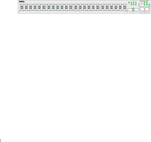
PowerConnect 3424
The PowerConnect 3424 provides 24 10/100Mbps ports plus two SFP ports, and two Copper ports which can be used to forward traffic in a stand-alone device, or as stacking ports when the device is stacked. The device also provides one RS-232 console port. The PowerConnect 3424 is a stackable device, but also operates as a stand-alone device.
PowerConnect 3424P
The PowerConnect 3424P provides 24 10/100Mbps ports plus two SFP ports, and two Copper ports which can be used to forward traffic in a stand-alone device, or as stacking ports when the device is stacked. The device also provides one RS-232 console port. The PowerConnect 3424P is a stackable device, but also operates as a stand-alone device. The PowerConnect 3424P also provides Power over Ethernet (PoE).
Figure 1-1. PowerConnect 3424 and PowerConnect 3424P
Introduction 21
w w w . d e l l . c o m | s u p p o r t . d e l l . c o m
PowerConnect 3448
The PowerConnect 3448 provides 48 10/100Mbps ports plus two SFP ports, and two Copper ports which can be used to forward traffic in a stand-alone device, or as stacking ports when the device is stacked. The device also provides one RS-232 console port. The PowerConnect 3448 is a stackable device, but also functions as a stand-alone device.
PowerConnect 3448P
The PowerConnect 3448P provides 48 10/100Mbps ports, two SFP ports, and two copper ports that can be used to forward traffic when the device is in stand-alone mode, or as stacking ports when the device is part of a stack. The device also provides one RS-232 console port. In addition, PowerConnect 3448P provides PoE.
Figure 1-2. PowerConnect 3448 and PowerConnect 3448P
Stacking Overview
PowerConnect 3424/P and PowerConnect 3448/P stacking provides multiple switch management through a single point as if all stack members are a single unit. All stack members are accessed through a single IP address through which the stack is managed. The stack is managed from a:
•Web-based interface
•SNMP Management Station
•Command Line Interface (CLI)
PowerConnect 3424/P and PowerConnect 3448/P devices support stacking up to six units per stack, or can operate as stand-alone units.
During the Stacking setup, one switch is selected as the Stack Master and another stacking member can be selected as the Backup Master. All other devices are selected as stack members, and assigned a unique Unit ID.
Switch software is downloaded separately for each stack members. However, all units in the stack must be running the same software version.
Switch stacking and configuration is maintained by the Stack Master. The Stack Master detects and reconfigures the ports with minimal operational impact in the event of:
•Unit Failure
•Inter-unit Stacking Link Failure
•Unit Insertion
•Removal of a Stacking Unit
22 Introduction
Understanding the Stack Topology
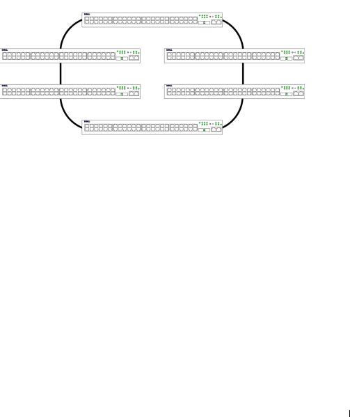
The PowerConnect 3400 series operates in a Ring topology. A stacked Ring topology is where all devices in the stack are connected to each other forming a circle. Each device in the stack accepts data and sends it to the device to which it is attached. The packet continues through the stack until it reaches its destination. The system discovers the optimal path on which to send traffic.
Figure 1-3. Stacking Ring Topology
Ring Topology
Most difficulties incurred in Ring topologies occur when a device in the ring becomes nonfunctional, or a link is severed. With the PowerConnect 3424/P and PowerConnect 3448/P stack, the system automatically switches to a Stacking Failover topology without any system downtime. An SNMP message is automatically generated, but no stack management action is required. However, the stacking link or stacking member must be repaired to ensure the stacking integrity.
After the stacking issues are resolved, the device can be reconnected to the stack without interruption, and the Ring topology is restored.
Stacking Failover Topology
If a failure occurs in the stacking topology, the stack reverts to Stacking Failover Topology. In the Stacking Failover topology, devices operate in a chain formation. The Stack Master determines where the packets are sent. Each unit is connected to two neighboring devices, except for the top and bottom units.
Stacking Members and Unit ID
Stacking Unit IDs are essential to the stacking configuration. The stacking operation is determined during the boot process. The operation mode is determined by the Unit ID selected during the initialization process. For example, if the user selected the stand-alone mode, the device boots in the boot-up process as a stand-alone device.
The device units are shipped with a default Unit ID of the stand-alone unit. If the device is operating as a stand-alone unit, all stacking LEDs are off.
Introduction 23

w w w . d e l l . c o m | s u p p o r t . d e l l . c o m
Once the user selects a different Unit ID, it is not erased, and remains valid, even if the unit is reset.
Unit ID 1 and Unit ID 2 are reserved for Master enabled units. Unit IDs 3 to 6 can be defined for stack members.
When the Master unit boots or when inserting or removing a stack member, the Master unit initiates a stacking discovering process.
NOTE: If two members are discovered with the same Unit ID the stack continues to function, however only the unit with the older join time joins the stack. A message is sent to the user, notifying that a unit failed to join the stack.
Removing and Replacing Stacking Members
Unit 1 and Unit 2 are Master enabled units. Unit 1 and Unit 2 are either designated as Master Unit or Backup Master Unit. The stack Master assignment is performed during the configuration process. One Master enabled stack member is elected as Master, and the other Master enabled stack member is elected as Backup Master, according to the following decision process:
•If only one Stack Master enabled unit is present, it is elected as the Master.
•If two Master enabled stacking members are present, and one has been manually configured as the Stack Master, the manually configured member is elected as Stack Master.
•If two Master enabled units are present and neither has been manually configured as the Master, the one with the longer up-time is elected as the Stack Master.
•If two Master enabled units are present and both have been manually configured as the Master, the one with the longer up-time is elected as the Stack Master.
•If the two Master enabled stacking members are the same age, Unit 1 is elected as the Stack Master.
NOTE: Two stacking member are considered the same age if they were inserted within a ten minute interval.
For example, Unit 2 is inserted in the first minute of a ten-minute cycle, and Unit 1 is inserted in fifth minute of the same cycle, the units are considered to be the same age. If there are two Master enabled stack members that are the same age, then Unit 1 is elected master.
The Stack Master and the Backup Master maintain a Warm Standby. The Warm Standby ensures that the Backup Master takes over for the Stack Master if a failover occurs. This guarantees that the stack continues to operate normally.
During the Warm Standby, the Master and the Backup Master are synchronized with the static configuration only. When the Stacking Master is configured, the Stack Master must synchronize the Stacking Backup Master. The Dynamic configuration is not saved, for example, dynamically learned MAC addresses are not saved.
Each port in the stack has a specific Unit ID, port type, and port number, which are part of both the configuration commands and the configuration files. Configuration files are managed only from the device Stack Master, including:
24 Introduction

•Saving to the FLASH
•Uploading Configuration files to an external TFTP Server
•Downloading Configuration files from an external TFTP Server
NOTE: Stack configuration for all configured ports is saved, even if the stack is reset and/or the ports are no longer present.
Whenever a reboot occurs, topology discovery is performed, and the Master learns all units in the stack. Unit IDs are saved in the unit and are learned through topology discovery. If a unit attempts to boot without a selected Master, and the unit is not operating in stand-alone mode, the unit does not boot.
Configuration files are changed only through explicit user configuration. Configuration files are not automatically modified when:
•Units are Added
•Units are Removed
•Units are reassigned Unit IDs
•Units toggle between Stacking Mode and Stand-alone Mode
Each time the system reboots, the Startup Configuration file in the Master unit is used to configure the stack.
If a stack member is removed from the stack, and then replaced with a unit with the same Unit ID, the stack member is configured with the original device configuration. Only ports which are physically present are displayed in the PowerConnect OpenManage Switch Administrator home page, and can be configured through the web management system. Non-present ports are configured through the CLI or SNMP interfaces.
Exchanging Stacking Members
If a stack member with the same Unit ID replaces an existing Unit ID with the same Unit ID, the previous device configuration is applied to the inserted stack member. If the new inserted device has either more or fewer ports than the previous device, the relevant port configuration is applied to the new stack member. For example,
•If a PowerConnect 3424/P replaces PowerConnect 3424/P, all port configurations remain the same.
•If a PowerConnect 3448/P replaces the PowerConnect 3448/P, all port configurations remain the same.
Introduction 25

w w w . d e l l . c o m | s u p p o r t . d e l l . c o m
Figure 1-4. PowerConnect 3448/P replaces PowerConnect 3448/P
Same |
Same |
Same |
Configuration |
Configuration |
Configuration |
•If a PowerConnect 3448/P replaces PowerConnect 3424/P, the first 3448/P 24 FE ports receive the 3424/P 24 FE port configuration. The GE port configurations remain the same. The remaining ports receive the default port configuration.
Figure 1-5. PowerConect 3424/P port replaces PowerConnect 3448/P port
Same |
Same |
Configuration |
Configuration |
Default
Configuration
•If a PowerConnect 3424/P replaces PowerConnect 3448/P, the PowerConnect 3424/P 24 FE ports receives the first 24 FE PowerConnect 3448/P port configuration. The GE port configurations remain the same.
26 Introduction
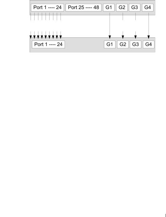
Figure 1-6. PowerConnect 3448/P port replaces PowerConect 3424/P Port
Same |
Same |
Configuration |
Configuration |
Switching from the Stack Master to the Backup Stack Master
The Backup Master replaces the Stack Master if the following events occur:
•The Stack Master fails or is removed from the stack.
•Links from the Stack Master to the stacking members fails.
•A soft switchover is performed with either via web interface or the CLI.
Switching between the Stack Master and the Backup Master results in a limited service loss. Any dynamic tables are relearned if a failure occurs. The running configuration file is synchronized between Stack Master and the Backup Master, and continues running on the Backup Master.
Introduction 27

w w w . d e l l . c o m | s u p p o r t . d e l l . c o m
Features Overview
This section describes the device features. For a complete list of all updated device features, see the latest software version Release Notes.
Power over Ethernet
Power over Ethernet (PoE) provides power to devices over existing LAN cabling, without updating or modifying the network infrastructure. PoE removes the need for placing network devices next to power sources. PoE can be used in the following applications:
•IP Phones
•Wireless Access Points
•IP Gateways
•PDAs
•Audio and video remote monitoring
For more information about Power over Ethernet, see "Managing Power over Ethernet".
Head of Line Blocking
Head of Line (HOL) blocking results in traffic delays and frame loss caused by traffic competing for the same egress port resources. HOL blocking queues packets, and the packets at the head of the queue are forwarded before packets at the end of the queue.
Flow Control Support (IEEE 802.3X)
Flow control enables lower speed devices to communicate with higher speed devices, by requesting that the higher speed device refrains from sending packets. Transmissions are temporarily halted to prevent buffer overflows.
For information on configuring Flow Control for ports or LAGs, see "Defining Port Configuration" or "Defining LAG Parameters."
Back Pressure Support
On half-duplex links, the receiving port prevents buffer overflows by occupying the link so that it is unavailable for additional traffic.
For information on configuring Flow Control for ports or LAGs, see "Defining Port Configuration" or "Defining LAG Parameters."
Virtual Cable Testing (VCT)
VCT detects and reports copper link cabling occurrences such as open cables and cable shorts. For more information on testing cables, see "Running Cable Diagnostics".
28 Introduction

MDI/MDIX Support
The device automatically detects whether the cable connected to an RJ-45 port is crossed or straight through, when auto-negotiation is enabled.
Standard wiring for end stations is Media-Dependent Interface (MDI) and the standard wiring for hubs and switches is known as Media-Dependent Interface with Crossover (MDIX).
For information on configuring MDI/MDIX for ports or LAGs, see "Defining Port Configuration" or "Defining LAG Parameters."
Auto Negotiation
Auto negotiation allows the device to advertise modes of operation. The auto negotiation function provides the means to exchange information between two devices that share a point-to-point link segment, and to automatically configure both devices to take maximum advantage of their transmission capabilities.
The PowerConnect 3400 series enhances auto negotiation by providing port advertisement. Port advertisement allows the system administrator to configure the port speeds that are advertised.
For more information on auto-negotiation, see "Defining Port Configuration" or "Defining LAG Parameters."
MAC Address Supported Features
MAC Address Capacity Support
The device supports up to 8K MAC addresses. The device reserves specific MAC addresses for system use.
Static MAC Entries
MAC entries can be manually entered in the Bridging Table, as an alternative to learning them from incoming frames. These user-defined entries are not subject to aging, and are preserved across resets and reboots.
For more information, see "Defining Static Addresses."
Self-Learning MAC Addresses
The device enables automatic MAC address learning from incoming packets. The MAC addresses are stored in the Bridging Table.
Automatic Aging for MAC Addresses
MAC addresses, from which no traffic is received for a given period, are aged out. This prevents the Bridging Table from overflowing.
For more information on configuring the MAC Address Age Out Time, see "Viewing Dynamic Addresses."
Introduction 29

w w w . d e l l . c o m | s u p p o r t . d e l l . c o m
VLAN-aware MAC-based Switching
The device always performs VLAN-aware bridging. Classic bridging(IEEE802.1D) is not performed, where frames are forwarded based only on their destination MAC address. However, a similar functionality can be configured for untagged frames. Frames addressed to a destination MAC address that is not associated with any port are flooded to all ports of the relevant VLAN.
MAC Multicast Support
Multicast service is a limited broadcast service, which allows one-to-many and many-to-many connections for information distribution. Layer 2 Multicast service is where a single frame is addressed to a specific Multicast address, from where copies of the frame are transmitted to the relevant ports.
For more information, see "Assigning Multicast Forward All Parameters."
Layer 2 Features
IGMP Snooping
IGMP Snooping examines IGMP frame contents, when they are forwarded by the device from work stations to an upstream Multicast router. From the frame, the device identifies work stations configured for Multicast sessions, and which Multicast routers are sending Multicast frames.
For more information, see "IGMP Snooping."
Port Mirroring
Port mirroring monitors and mirrors network traffic by forwarding copies of incoming and outgoing packets from a monitored port to a monitoring port. Users specify which target port receives copies of all traffic passing through a specified source port.
For more information, see "Defining Port Mirroring Sessions."
Broadcast Storm Control
Storm Control enables limiting the amount of Multicast and Broadcast frames accepted and forwarded by the device.
When Layer 2 frames are forwarded, Broadcast and Multicast frames are flooded to all ports on the relevant VLAN. This occupies bandwidth, and loads all nodes connected on all ports.
For more information, see "Enabling Storm Control."
30 Introduction
Loading...