


3348
Table of contents
 Loading...
www.dell.com | support.dell.com
Dell™ PowerConnect™ 3324/3348
User’s Guide
Model PowerConnect 3324/3348

Notes, Notices, and Cautions
NOTE: Notes indicate important information that helps you make better use of your device.
NOTICE: Notices indicate either potential damage to hardware or loss of data and tells you
how to avoid the problem.
CAUTION: Caution indicates a potential for property damage, personal injury, or
death.
Information in this document is subject to change without notice.
© 2003 Dell Inc. All rights reserved.
Reproduction in any manner whatsoever without the written permission of Dell Inc. is strictly forbidden.
Trademarks used in this text: Dell, the DELL logo, PowerConnect, Dell O penManage, PowerEdge, Inspiron, Dell
Precision, Dimension, OptiPlex, Axim, PowerVault, PowerApp, DellNet, and Latitude are trademarks of Dell Inc.;
Microsoft and Windows are registered trademarks of Microsoft Corporation.
Other trademarks and trade names may be used in this document to refer to either the entities claiming the marks and
names or their products. Dell Inc. disclaims any proprietary interest in trademarks and trade names other than its own.
November 2003 Rev. A01

Contents 3
Contents
1 Overview
System Description . . . . . . . . . . . . . . . . . . . . . . . . . 12
PowerConnect 3324/3348 Stacking Overview
. . . . . . . . . . . 12
Stack Members and Unit ID
. . . . . . . . . . . . . . . . . . . 13
Configuration Handling
. . . . . . . . . . . . . . . . . . . . . 14
Rearranging Stacks
. . . . . . . . . . . . . . . . . . . . . . . 15
Replacing Stack Members
. . . . . . . . . . . . . . . . . . . . 15
PowerConnect User Guide Overview
. . . . . . . . . . . . . . . . 17
Installing the PowerConnect 3324/3348 Switch
. . . . . . . . . 17
Using the Dell OpenManage Switch Administrator
. . . . . . . . 17
PowerConnect 3324/3348 CLI Documentation
. . . . . . . . . . 18
2 Hardware Description
PowerConnect 3324/3348 Description . . . . . . . . . . . . . . . 20
PowerConnect 3324/3348 Dimensions
. . . . . . . . . . . . . 20
PowerConnect 3324/3348 Rear Panel
. . . . . . . . . . . . . . 20
PowerConnect 3324/3348 Components
. . . . . . . . . . . . . 20
Ports Description
. . . . . . . . . . . . . . . . . . . . . . . . . . 24
Ethernet Port Description
. . . . . . . . . . . . . . . . . . . . 24
Console Port Description
. . . . . . . . . . . . . . . . . . . . 24
LED Definitions
. . . . . . . . . . . . . . . . . . . . . . . . . . . 24
Port LEDs
. . . . . . . . . . . . . . . . . . . . . . . . . . . 26
System LEDs
. . . . . . . . . . . . . . . . . . . . . . . . . . 26
Stacking LEDs
. . . . . . . . . . . . . . . . . . . . . . . . . 28

4 Contents
3 Installing the PowerConnect 3324/3348 Switch
Installation Precautions . . . . . . . . . . . . . . . . . . . . . . 30
Site Requirements
. . . . . . . . . . . . . . . . . . . . . . . . . 30
Unpacking and Installation
. . . . . . . . . . . . . . . . . . . . 31
Package Contents
. . . . . . . . . . . . . . . . . . . . . . . 31
Unpacking
. . . . . . . . . . . . . . . . . . . . . . . . . . . 31
Device Rack Installation
. . . . . . . . . . . . . . . . . . . . 32
Installing the Switch without a Rack
. . . . . . . . . . . . . . 32
Stacking PowerConnect 3324/3348
. . . . . . . . . . . . . . 33
Connecting Stacking Cables
. . . . . . . . . . . . . . . . . . 33
Connecting the PowerConnect 3324/3348 to a
Power Supply
. . . . . . . . . . . . . . . . . . . . . . . . . 34
Cable, Port, and Pinout Information
. . . . . . . . . . . . . . . 35
Port Connections
. . . . . . . . . . . . . . . . . . . . . . . . 36
Cable Connections
. . . . . . . . . . . . . . . . . . . . . . . 38
4 Configuring the PowerConnect 3324/3348 Switch
Configuration Overview . . . . . . . . . . . . . . . . . . . . . . 42
General Configuration Information
. . . . . . . . . . . . . . . . 43
Auto-Negotiation
. . . . . . . . . . . . . . . . . . . . . . . 43
Switching Port Default Settings
. . . . . . . . . . . . . . . . 44
Baud Rate
. . . . . . . . . . . . . . . . . . . . . . . . . . . 45
Terminal Connection Configuration
. . . . . . . . . . . . . . . . 45
Other Configuration Requirements
. . . . . . . . . . . . . . . . 46
Booting the Device
. . . . . . . . . . . . . . . . . . . . . . . . 46
Device Configuration Introduction
. . . . . . . . . . . . . . . . 48
Initial Configuration
. . . . . . . . . . . . . . . . . . . . . . . . 49
Static IP Address and Subnet Mask
. . . . . . . . . . . . . . 49
Default Gateway
. . . . . . . . . . . . . . . . . . . . . . . . 51

Contents 5
User Name, Password, and Privilege Level . . . . . . . . . . . 51
SNMP Community Strings
. . . . . . . . . . . . . . . . . . . 51
Advanced Configuration
. . . . . . . . . . . . . . . . . . . . . . 53
Retrieving an IP address from a DHCP Server
. . . . . . . . . 54
Receiving an IP address from a BOOTP Server
. . . . . . . . . 55
Security Management and Password Configuration
. . . . . . . 56
Configuring Security Passwords
. . . . . . . . . . . . . . . . . 57
Sample Configuration Process
. . . . . . . . . . . . . . . . . . . 60
Device Setup Requirements
. . . . . . . . . . . . . . . . . . . 60
Initial Connection
. . . . . . . . . . . . . . . . . . . . . . . . 60
Device Default Settings
. . . . . . . . . . . . . . . . . . . . . 64
Remote Management Access
. . . . . . . . . . . . . . . . . . 65
Start Running the Management Station
. . . . . . . . . . . . . 68
Telnet access
. . . . . . . . . . . . . . . . . . . . . . . . . . 70
Web Access (HTTP server)
. . . . . . . . . . . . . . . . . . . 72
Configuring Stacking
. . . . . . . . . . . . . . . . . . . . . . . . 75
Stacking Introduction
. . . . . . . . . . . . . . . . . . . . . . 75
Stacking Requirements
. . . . . . . . . . . . . . . . . . . . . 75
Configuring a Stack
. . . . . . . . . . . . . . . . . . . . . . . 75
Expanding the Stack
. . . . . . . . . . . . . . . . . . . . . . 76
Rebooting the Device
. . . . . . . . . . . . . . . . . . . . . . . . 76
Startup Menu Functions
. . . . . . . . . . . . . . . . . . . . . . 77
Downloading the Software
. . . . . . . . . . . . . . . . . . . 77
Erasing the FLASH File
. . . . . . . . . . . . . . . . . . . . 78
Erasing FLASH Sectors
. . . . . . . . . . . . . . . . . . . . 79
Password Recovery
. . . . . . . . . . . . . . . . . . . . . . . 80
Running Diagnostics
. . . . . . . . . . . . . . . . . . . . . . . 80
Downloading the Software to Stacking Units
. . . . . . . . . . . 80
Downloading the Software Sequentially Using the CLI
. . . . . 81
Downloading the Software Individually Using the CLI
. . . . . . 82
Downloading the Software Via the
PowerConnect 3324/3348 Dell OpenManage Switch
Administrator
. . . . . . . . . . . . . . . . . . . . . . . . . . 84

6 Contents
Defining SNMP Settings . . . . . . . . . . . . . . . . . . . . . 85
Connecting Devices
. . . . . . . . . . . . . . . . . . . . . . . . 86
5 Getting Started
Starting the Switch Administrator . . . . . . . . . . . . . . . . 88
Understanding the Interface
. . . . . . . . . . . . . . . . . . . 88
Tree View
. . . . . . . . . . . . . . . . . . . . . . . . . . . 89
Device View
. . . . . . . . . . . . . . . . . . . . . . . . . . 90
Device Representation
. . . . . . . . . . . . . . . . . . . . . 90
Using the Switch Administrator Buttons
. . . . . . . . . . . . . 92
Information Buttons
. . . . . . . . . . . . . . . . . . . . . . 93
About PageDevice Management Buttons
. . . . . . . . . . . . 95
Using the CLI
. . . . . . . . . . . . . . . . . . . . . . . . . . . 97
Command Mode
. . . . . . . . . . . . . . . . . . . . . . . . 97
User EXEC Mode
. . . . . . . . . . . . . . . . . . . . . . . 97
Privileged EXEC Mode
. . . . . . . . . . . . . . . . . . . . 98
Global Configuration Mode
. . . . . . . . . . . . . . . . . . 99
Interface Configuration Mode
. . . . . . . . . . . . . . . . . 99
Starting the CLI
. . . . . . . . . . . . . . . . . . . . . . . . . . 100
Console Connection
. . . . . . . . . . . . . . . . . . . . . . 100
Telnet Connection
. . . . . . . . . . . . . . . . . . . . . . . 101
6 Configuring System Information
Defining General Device Information . . . . . . . . . . . . . . . 104
Viewing the Asset Page
. . . . . . . . . . . . . . . . . . . . 105
Viewing System Health Information
. . . . . . . . . . . . . . 109
Viewing the Versions Page
. . . . . . . . . . . . . . . . . . . 110
Resetting the Device
. . . . . . . . . . . . . . . . . . . . . . 112

Contents 7
Managing Logs . . . . . . . . . . . . . . . . . . . . . . . . . . 113
Defining Global Log Parameters
. . . . . . . . . . . . . . . . 114
Displaying RAM Log Table
. . . . . . . . . . . . . . . . . . 118
Displaying the Log File Table
. . . . . . . . . . . . . . . . . 121
Displaying the Log File Table Using the CLI Commands
. . . . 121
Viewing the Remote Log Server Settings Page
. . . . . . . . . 123
Defining Device IP Addresses
. . . . . . . . . . . . . . . . . . 126
Defining Default Gateways
. . . . . . . . . . . . . . . . . . 127
Defining IP Interfaces
. . . . . . . . . . . . . . . . . . . . . 130
Defining DHCP IP Interfaces
. . . . . . . . . . . . . . . . . 133
Configuring ARP
. . . . . . . . . . . . . . . . . . . . . . . 136
Managing Device Security
. . . . . . . . . . . . . . . . . . . . 139
Defining Access Profiles
. . . . . . . . . . . . . . . . . . . . 141
Defining Authentication Profiles
. . . . . . . . . . . . . . . . 148
Assigning Authentication Profiles
. . . . . . . . . . . . . . . 152
Defining the Local User Databases
. . . . . . . . . . . . . . 157
Defining Line Passwords
. . . . . . . . . . . . . . . . . . . 160
Defining Enable Password
. . . . . . . . . . . . . . . . . . . 161
Configuring RADIUS Global Parameters
. . . . . . . . . . . 163
Defining SNMP Parameters
. . . . . . . . . . . . . . . . . . . 168
Defining Communities
. . . . . . . . . . . . . . . . . . . . . 169
Defining Traps
. . . . . . . . . . . . . . . . . . . . . . . . 171
Managing Files
. . . . . . . . . . . . . . . . . . . . . . . . . . 175
File Management Overview
. . . . . . . . . . . . . . . . . . 176
Downloading Files
. . . . . . . . . . . . . . . . . . . . . . . 177
Uploading Files
. . . . . . . . . . . . . . . . . . . . . . . . 180
Resetting the Active Image
. . . . . . . . . . . . . . . . . . 182
Copying and Deleting Files
. . . . . . . . . . . . . . . . . . 183
Defining Advanced Settings . . . . . . . . . . . . . . . . . . . 186
Configuring General Device Tuning Parameters
. . . . . . . . 187

8 Contents
7 Configuring Switch Information
Configuring Network Security . . . . . . . . . . . . . . . . . . 190
Network Security Overview
. . . . . . . . . . . . . . . . . . 191
Configuring Port Security
. . . . . . . . . . . . . . . . . . . 193
Defining IP-Based ACLs
. . . . . . . . . . . . . . . . . . . . 196
Defining MAC-Based ACLs
. . . . . . . . . . . . . . . . . . 200
Binding ACLs
. . . . . . . . . . . . . . . . . . . . . . . . . 205
Configuring Ports
. . . . . . . . . . . . . . . . . . . . . . . . . 207
Defining Port Parameters
. . . . . . . . . . . . . . . . . . . 208
Defining LAG Parameters
. . . . . . . . . . . . . . . . . . . 216
Enabling Storm Control
. . . . . . . . . . . . . . . . . . . . 222
Defining Port Mirroring Sessions
. . . . . . . . . . . . . . . . 225
Configuring Address Tables
. . . . . . . . . . . . . . . . . . . . 229
Defining Static Addresses
. . . . . . . . . . . . . . . . . . . 230
Viewing Dynamic Addresses
. . . . . . . . . . . . . . . . . . 233
Configuring GARP
. . . . . . . . . . . . . . . . . . . . . . . . . 235
Defining GARP Timers
. . . . . . . . . . . . . . . . . . . . . 236
Configuring the Spanning Tree Protocol
. . . . . . . . . . . . . 239
Defining STP Global Settings
. . . . . . . . . . . . . . . . . 240
Defining STP Port Settings
. . . . . . . . . . . . . . . . . . 244
Defining STP LAG Settings
. . . . . . . . . . . . . . . . . . 248
Configuring Rapid Spanning Tree
. . . . . . . . . . . . . . . . 251
Configuring VLANs
. . . . . . . . . . . . . . . . . . . . . . . . 254
Defining VLAN Members
. . . . . . . . . . . . . . . . . . . 256
Defining VLAN Ports Settings
. . . . . . . . . . . . . . . . . 261
Defining VLAN LAG Settings
. . . . . . . . . . . . . . . . . 264
Configuring GVRP
. . . . . . . . . . . . . . . . . . . . . . . 267
Aggregating Ports
. . . . . . . . . . . . . . . . . . . . . . . . . 272
Defining LACP Parameters
. . . . . . . . . . . . . . . . . . 274
Defining LAG Membership
. . . . . . . . . . . . . . . . . . . 279

Contents 9
Multicast Forwarding Support . . . . . . . . . . . . . . . . . . 280
Defining IGMP Snooping Settings
. . . . . . . . . . . . . . . 281
Adding Bridge Multicast Group Members
. . . . . . . . . . . 284
Assigning Multicast Forward All Parameters
. . . . . . . . . 287
Enabling IGMP Snooping
. . . . . . . . . . . . . . . . . . . 289
8 Viewing Statistics
Viewing Tables . . . . . . . . . . . . . . . . . . . . . . . . . . 294
Viewing Utilization Summary
. . . . . . . . . . . . . . . . . 295
Viewing Counter Summary
. . . . . . . . . . . . . . . . . . 297
Viewing Interface Statistics
. . . . . . . . . . . . . . . . . . 298
Viewing Interface Statistics Using the CLI Commands
. . . . 300
Viewing Etherlike Statistics
. . . . . . . . . . . . . . . . . . 301
Viewing GVRP Statistics
. . . . . . . . . . . . . . . . . . . 304
Viewing GVRP Statistics Using the CLI Commands
. . . . . . 305
Viewing RMON Information
. . . . . . . . . . . . . . . . . . . 307
Viewing RMON Statistics
. . . . . . . . . . . . . . . . . . . 307
Viewing History Control Statistics
. . . . . . . . . . . . . . 310
Viewing The RMON History Table
. . . . . . . . . . . . . . . 313
Defining Device Events
. . . . . . . . . . . . . . . . . . . . 316
Viewing the Events Log
. . . . . . . . . . . . . . . . . . . . 320
Defining Device Alarms
. . . . . . . . . . . . . . . . . . . . 321
Viewing Charts
. . . . . . . . . . . . . . . . . . . . . . . . . . 326
Viewing Port Statistics
. . . . . . . . . . . . . . . . . . . . 327
Viewing LAG Statistics
. . . . . . . . . . . . . . . . . . . . 331
9 Configuring Quality of Service
Quality of Service (QoS) Overview . . . . . . . . . . . . . . . . 336

10 Contents
Defining QoS Global Parameters . . . . . . . . . . . . . . . . . 339
Configuring Global QoS Settings
. . . . . . . . . . . . . . . . 340
Defining QoS Interface Settings
. . . . . . . . . . . . . . . . 342
Defining Queue Settings
. . . . . . . . . . . . . . . . . . . . 343
Mapping to Queues
. . . . . . . . . . . . . . . . . . . . . . . . 346
Mapping CoS Values to Queues
. . . . . . . . . . . . . . . . 346
Mapping DSCP Values to Queues
. . . . . . . . . . . . . . . . 348
Mapping TCP Port Values to Queues
. . . . . . . . . . . . . . 350
Mapping UDP Port Values to Queues
. . . . . . . . . . . . . . 353
10 Getting Help
Technical Assistance . . . . . . . . . . . . . . . . . . . . . . . . 358
Online Services
. . . . . . . . . . . . . . . . . . . . . . . . 358
AutoTech Service
. . . . . . . . . . . . . . . . . . . . . . . 359
Automated Order-Status Service
. . . . . . . . . . . . . . . . 359
Technical Support Service
. . . . . . . . . . . . . . . . . . . 360
Dell Enterprise Training and Certification
. . . . . . . . . . . . 360
Problems With Your Order
. . . . . . . . . . . . . . . . . . . . . 360
Product Information
. . . . . . . . . . . . . . . . . . . . . . . . 360
Returning Items for Warranty Repair or Credit . . . . . . . . . . 360
Before You Call
. . . . . . . . . . . . . . . . . . . . . . . . . . 361
Contacting Dell
. . . . . . . . . . . . . . . . . . . . . . . . . . 361

SECTION 1
Overview
System Description
PowerConnect 3324/3348 Stacking Overview
PowerConnect User Guide Overview
PowerConnect 3324/3348 CLI Documentation
12 Overview
www.dell.com | support.dell.com
System Description
The Dell™ PowerConnect™ 3324 and 3348 devices are standalone and stackable advanced
Layer 2 switches. PowerConnect 3324 and PowerConnect 3348 also function as stand-alone
Layer 2 switching systems. PowerConnect 3324/3348 devices are managed either using In-
Band Management (via the network station remotely) or via the console.
PowerConnect 3324
When operating as a stack member, each PowerConnect 3324 unit provides 24 10
BaseT/100BaseTX Fast Ethernet ports, one Gigabit Ethernet Combo port (10/100/1000
BaseT or Mini GBIC connector), and one Giga Ethernet stacking port.
PowerConnect 3348
When operating as a stack member, each PowerConnect 3348 unit provides 48 10
BaseT/100BaseTX Fast Ethernet ports, one Gigabit Ethernet Combo port (10/100/1000
BaseT or Mini GBIC connector), and one Giga Ethernet stacking port.
When operating as a stand-alone unit, the PowerConnect 3324/3348 stacking ports can be
used as Giga Ethernet ports.
PowerConnect 3324/3348 Stacking Overview
PowerConnect 3324/3348 stacking provides multiple device management through a single
point as if all stack members are a single unit. All members are accessed through a single IP
address for SNMP management and a console/telnet session through which the entire stack
is managed.
PowerConnect 3324/3348 supports stacking up to six units per stack or scale up to 192 FE
and six Gigabit Ethernet ports. PowerConnect 3324/3348 can also operate as standalone
units.

Overview 13
During the stacking setup, one device is selected by the network administrator as the stack
master, while all other devices are selected as stack members and assigned a unique Unit ID.
PowerConnect 3324/3348 stacks provide across-the-stack Layer 2 functionality including:
• Switching
• Trunking
• Port Mirroring
•VLANs
For example, VLANs can be configured from ports belonging to different stack members, or
configure port mirroring from a second stack member to a third stack member. Applications
running in a stacking configuration are centralized. For example, the Spanning Tree
Protocol for the entire stack runs on the master unit. Device software is downloaded
separately for each stack member.
PowerConnect 3324/3348 stacking architecture provides dynamic learning for the stacking
topology, while detecting and reconfiguring the ports with minimal operational impact in
the event of:
• Unit Failure
• Inter-unit Link Loss
• Unit Insertion
• Removal of a Stacking Unit
Stack Members and Unit ID
The stacking operation mode is determined during the Boot process.
PowerConnect 3324/3348 units are shipped with a default Unit ID of one. The Unit ID is
essential to the stacking configuration. If a stack member reboots without a stacking
module, the device operates as a stand-alone until the device is reset. If a PowerConnect
3324/3348 unit is operating as a stand-alone unit, all stacking LEDs are off. The Unit ID is
not erased and remains valid if the unit is reconnected to a stack.
NOTE: The stacking module must be inserted into port G2 for the stack to operate. If the
stacking module is inserted in port G1, a warning message is displayed on the console.

14 Overview
www.dell.com | support.dell.com
When the master unit boots or when inserting or removing a stack member, the master unit
initiates a stacking discover process. If two members are discovered with the same Unit ID,
or a master unit is not found, the entire stack cannot function. The stacking LED remains
red.
Configuration Handling
In a PowerConnect 3324/3348 operative stack, the stack master is responsible for the stack
configuration. Each stack member does not have a separate configuration file. Each port in
the stack has a specific Unit ID/port type and port number, which is part of both the
configuration commands and the configuration files. Configuration files are managed only
from the PowerConnect 3324/3348 stack master, including:
• Saving to the FLASH.
• Uploading Configuration files to an external TFTP Server.
• Downloading Configuration files from an external TFTP Server.
NOTE: Stack configuration for all configured ports is saved, even if the stack is reset and/or the
ports are no longer present.
Configuration files are changed only through explicit user configuration. In addition,
Configuration files are not automatically modified when:
• Units are added.
• Units are removed.
• Units are reassigned Unit IDs.
• Units toggle between stacking mode and stand-alone mode.
Each time the system reboots, the stored configuration is written in the Startup
Configuration file.
If a PowerConnect 3324/3348 stack member is removed from the stack, and then replaced
with the same Unit ID, the stack member is configured with the original device
configuration.
Only ports that are physically present are displayed in the Dell OpenManage™ Switch
Administrator and can be configured through the web management system. Non-present
ports are configured through the CLI or SNMP interfaces.

Overview 15
Rearranging Stacks
The stacking order can be changed by either removing a stack member or by rearranging the
stacking cables. The order in which stack members are arranged is established not by the
physical order of the stack members but by the Unit ID assignment. The stack
configuration is stored in stack master after the stack order is changed, and the stack is
reset.
If the PowerConnect 3324/3348 unit is removed or replaced in a stack, the stack recovers
from the disconnection as follows:
• If the stack is disconnected for more than two minutes, the entire stack no longer
forwards network traffic. Every stack member reboots and waits until the stack is
reconnected. If the unit is not replaced, the master unit constantly polls the stack.
• If the stack is reconnected in under two minutes, all units remain stacked and regain
their connection to other units within five seconds. A new stack member is connected
to the master unit but initialized according to the master unit’s configuration. If a
configuration is not stored, the device is configured with the default configuration.
Replacing Stack Members
If a stack member is replaced with a new device, the requested device ID is selected. In
addition, the previous device configuration is applied to the inserted stack member. If the
new inserted device has either more or fewer ports than the previous device, the relevant
port configuration is applied to the new stack member. For example:
• If a PowerConnect 3324 replaces a PowerConnect 3324, the new 24 10/100 BaseT
ports receive the previous 24 10/100 BaseT port configuration. Ports G1 and G2 receive
the previous device’s G1 and G2 port configuration.
• If a PowerConnect 3324 replaces PowerConnect 3348, then ports 1-24 10/100 BaseT
receive the previous device’s configuration for ports 1-24. Ports G1 and G2 receive the
previous device’s G1 and G2 port configuration.
16 Overview
www.dell.com | support.dell.com
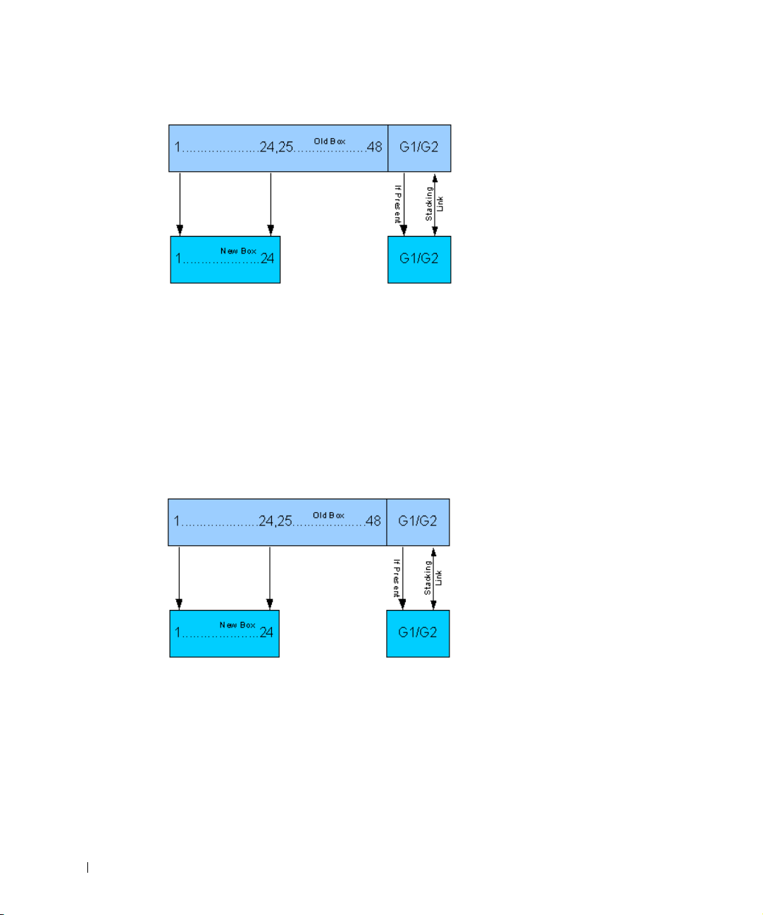
PowerConnect 3324 Replaces PowerConnect 3348
• If a PowerConnect 3348 replaces PowerConnect 3348, the new 48 10/100 BaseT ports
receive the previous 48 10/100 BaseT port configuration. Ports G1 and G2 receive the
previous device’s G1 and G2 port configuration.
• If a PowerConnect 3348 replaces PowerConnect 3324, then ports 1-24 10/100 BaseT
receive the previous device’s configuration for ports 1-24.
• Ports 25-48 receive the factory default port configuration. Ports G1 and G2 receive the
previous device’s G1 and G2 port configuration.
PowerConnect 3348 Replace PowerConnect 3324

Overview 17
PowerConnect User Guide Overview
The PowerConnect User Guide is divided into two parts:
• About Installing the PowerConnect 3324/3348 Switch
• Using the Dell OpenManage Switch Administrator
Installing the PowerConnect 3324/3348 Switch
This section contains the following sections about unpacking, installing, and configuring
the PowerConnect 3324/3348:
• Hardware Description—Contains information about the PowerConnect 3324/3348
hardware, including a description of the ports and LED types.
• Installing the PowerConnect 3324/3348 Switch—Contains instructions about
installing PowerConnect 3324/3348 in either a rack or on a flat surface. In addition,
this section contains installation precautions, and a description of the connectors and
cables.
• Configuring the PowerConnect 3324/3348 Switch—Contains instructions about
initial device configuration, including downloading device software, the device boot
screen, and optional configuration functions.
Using the Dell OpenManage Switch Administrator
This section contains the following information about configuring the device using the web
management system and Command Line Interface (CLI) device management system:
• Getting Started—Contains information about getting started with the web
management system interface, including an explanation of the management and
information icons, the Components List, and the Device and Tr e e Views.
• Configuring System Information—Contains information about configuring general
system information including defining system information, configuring a default IP
address, defining device security and SNMP communities, downloading the device
software, and defining advanced settings.
• Configuring Switch Information—Contains information about configuring port and
VLANs, defining both static and dynamic address tables, configuring GARP and
GVRP, defining Spanning Tree parameters, aggregating ports, and configuring
Multicast forwarding support.
• Viewing Statistics—Contains information about viewing table and chart statistics for
ports, GVRP, Etherlike, RMON, and interface statistics.

18 Overview
www.dell.com | support.dell.com
• Configuring Quality of Service—Contains information about configuring device Class
of Service.
• Getting Help—Contains information about technical assistance, problems with your
order, returning items for repair or credit, and how to contact Dell.
PowerConnect 3324/3348 CLI Documentation
In addition to the PowerConnect 3324/3348 User Guide, Dell provides the PowerConnect
3324/3348 CLI Reference Guide. The PowerConnect 3324/3348 CLI Reference Guide
provides information about the CLI commands used to configure the PowerConnect
3324/3348.

SECTION 2
Hardware Description
PowerConnect 3324/3348 Description
Ports Description
LED Definitions
20 Hardware Description
www.dell.com | support.dell.com
PowerConnect 3324/3348 Description
PowerConnect 3324/3348 Dimensions
This device has the following dimensions:
• Width—19”
• Height—1U
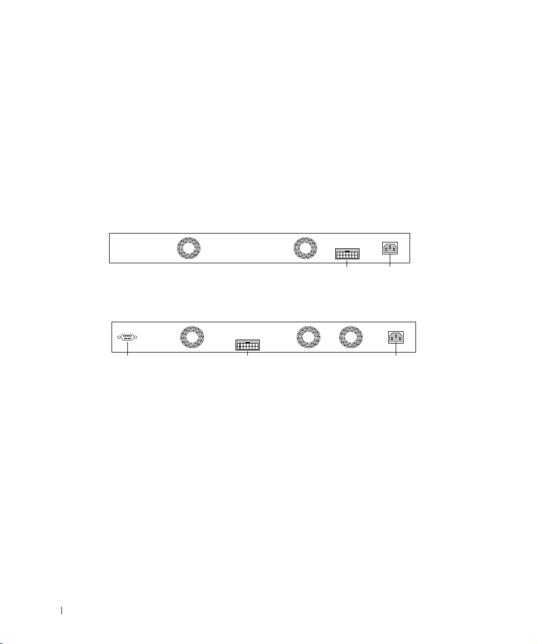
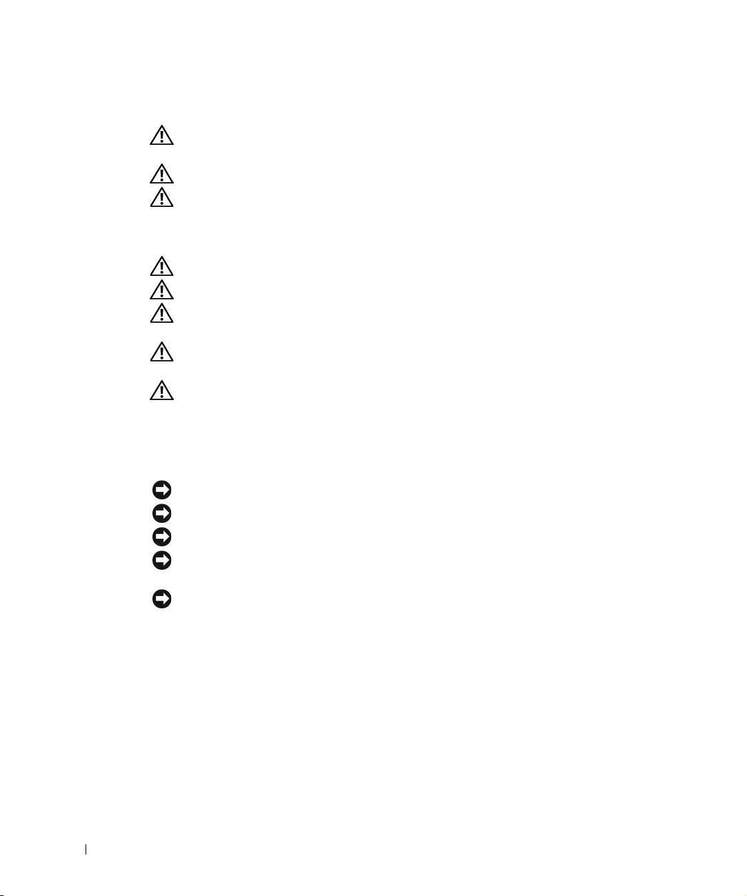
PowerConnect 3324/3348 Rear Panel
The rear panel of the Dell™ PowerConnect™ 3324/3348 is shown in the following figure:
PowerConnect 3324 Rear Panel
PowerConnect 3348 Rear Panel
PowerConnect 3324/3348 Components
This section describes different PowerConnect 3324/3348 hardware components, and
includes the following topics:
• General Device Components
• Mode Button
• Stack ID Button
RPS - DC
Power
Connector
RPS Connector
RPS - DC
Power ConnectorRPS ConnectorConsole Port
Hardware Description 21
General Device Components
The PowerConnect 3324/3348 includes the following hardware components:
• CPU—Based on Motorola’s MPC 8245.
• FLASH—Contains 8 MB of FLASH Memory.
• SDRAM—Contains 32 MB.
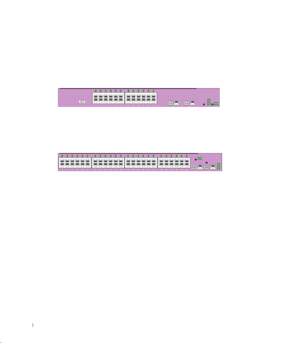
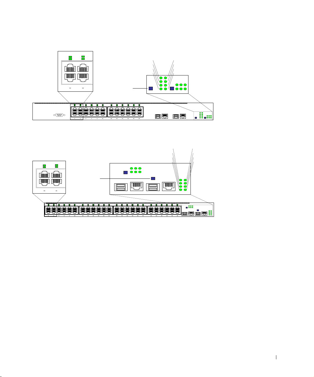
PowerConnect 3324 Front Panel
PowerConnect 3348 Front Panel
G1 G2
2
1
4
3
6
5
8
7
10
9
12
11
14
13
16
15
18
17
20
19
22
21
24
23
2
1
4
3
6
5
8
7
10
9
12
11
14
13
16
15
18
17
20
19
22
21
24
23
123
456
Stack ID Button
123
456
Stacking LEDs
26
25
28
27
30
29
32
31
34
33
36
35
38
37
40
39
42
41
44
43
46
45
48
47
26
25
28
27
30
29
32
31
34
33
36
35
38
37
40
39
42
41
44
43
46
45
48
47
2
1
4
3
6
5
8
7
10
9
12
11
14
13
16
15
18
17
20
19
22
21
24
23
2
1
4
3
6
5
8
7
10
9
12
11
14
13
16
15
18
17
20
19
22
21
24
23
G1 G2
123
456
G1 G2
123
456
Stacking LEDs
Stack ID Button

22 Hardware Description
www.dell.com | support.dell.com
Mode Button
The Mode Button toggles between port activity and port duplex settings.
Stack ID Button
The PowerConnect 3324/3348 front panel contains a Stack ID button that permits network
administrators to manually select the Stack Master and stack members.
NOTE: The Stack Master and stack members must be selected within 15 seconds after booting
the device. If the Stack Master is not selected within 15 seconds, the device must be reset to
select the Unit IDs.
Once the Stack Master is selected, the remaining devices are defined as stack members.
Master units receive the Unit ID of 1. Stack members receive a separate Unit ID (2-6). For
example, if there are 4 units in a stack, the Master unit is 1, the second stack member is 2,
the third stack member is 3, and the fourth stack member is 4.
Stacking Modules and Connectors
PowerConnect 3324/3348 Stacking modules are connected to port G2. The Stack module is
a mini GBIC module with two stacking connectors: RX and TX. RX is the lower connection
point, and TX is the upper connection point. The module is connected to other stacking
units using a stacking cable connection. The top unit’s RX is connected to the lower unit’s
TX. This completes the Ring Topology. The Stacking Connections figure illustrates the
Ring Topology.

Hardware Description 23
Stacking Connections
For more information about connecting Stacking cables, see "Connecting Stacking Cables".
Tx
Rx
Tx
Rx
Tx
Rx
Tx
Rx
Master Unit
#1
Member Unit
#1
Member Unit
#2
Member Unit
#3

24 Hardware Description
www.dell.com | support.dell.com
Ports Description
Ethernet Port Description
The PowerConnect 3324 features 24 FE 10BaseT/100BaseTX UTP copper RJ45 ports per
unit and 2 combo ports. The PowerConnect 3348 features 48 FE 10BaseT/100BaseTX UTP
copper RJ45 ports per unit and 2 combo ports. Each combo port is a single logical port that
has the following two physical interfaces:
• 1000Base-T connectors.
• Mini-GBIC (SFP) connectors.
Only one of the two physical connections of a combo port may be used at any one time.
If auto-MDIX is enabled, PowerConnect 3324/3348 automatically detects and corrects the
difference between crossover and straight-through cables on all ports.
PowerConnect 3324/3348 supports half and full duplex mode 10/100 M bps speed for
copper ports.
Console Port Description
The console port interface supports synchronous data of eight data bits, one stop bit, and
no parity. All RS232 pins are supported (9 pins) for Modem support.
LED Definitions
The front panel LEDs in the following figures indicate the status of port links and modes,
power supply status, stacking status, and system diagnostics. The LED types are as follows:
• Port LEDs
• System LEDs
• Stacking LEDs
Hardware Description 25
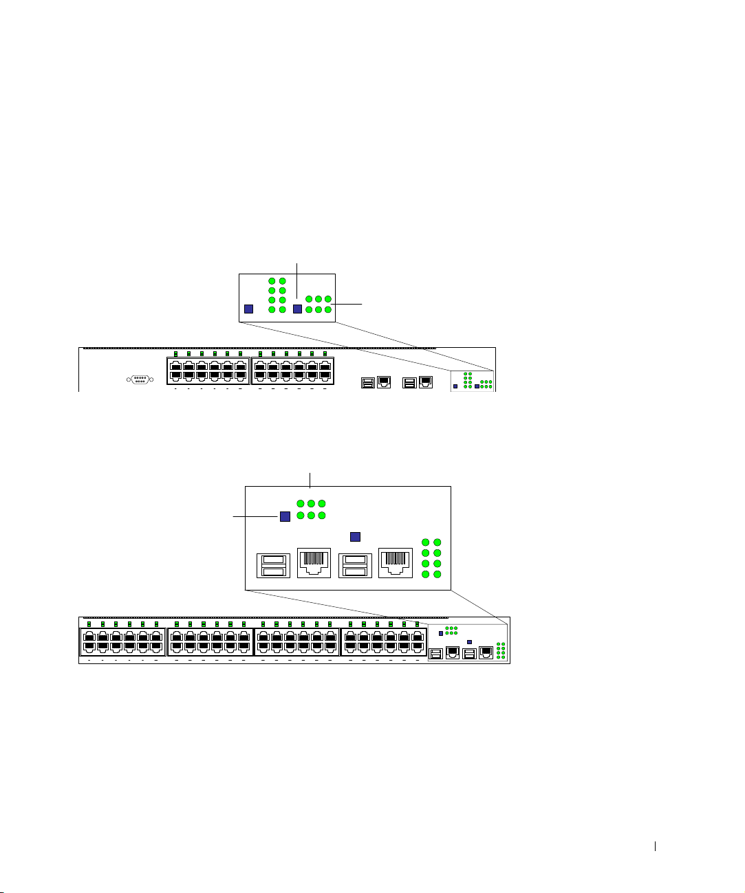
Front Panel LEDs: 24 Ports
Front Panel LEDs: 48 Ports
G1 G2
2
1
4
3
6
5
8
7
10
9
12
11
14
13
16
15
18
17
20
19
22
21
24
23
2
1
4
3
6
5
8
7
10
9
12
11
14
13
16
15
18
17
20
19
22
21
24
23
123
456
123
456
Mode
Button
2
1
4
3
2
1
4
3
System LEDs
G1
G2
Link/Act
Duplex
PWR
Diag
RPS
Stack
26
25
28
27
30
29
32
31
34
33
36
35
38
37
40
39
42
41
44
43
46
45
48
47
26
25
28
27
30
29
32
31
34
33
36
35
38
37
40
39
42
41
44
43
46
45
48
47
2
1
4
3
6
5
8
7
10
9
12
11
14
13
16
15
18
17
20
19
22
21
24
23
2
1
4
3
6
5
8
7
10
9
12
11
14
13
16
15
18
17
20
19
22
21
24
23
49 50
123
456
G1 G2
123
456
Mode
Button
2
1
4
3
2
1
4
3
System LEDs
G1
G2
Link/Act
Duplex
PWR
Diag
RPS
Stack

26 Hardware Description
www.dell.com | support.dell.com
Port LEDs
Each port has one corresponding LED located above the port. The LEDs show either link
activity or duplex mode, depending on the port LED display mode. For information about
setting the LED display mode, see "System LEDs".
Port Link Activity
Port Duplex Mode
System LEDs
The eight system LEDs indicate the status of various aspects of the device:
• As shown in the front panel figures at the start of this section, the two system LEDs on
the upper left side represent Link Activity and Duplex. These LEDs indicate whether
the port LEDs are displaying link activity or duplex status.
• The two LEDs on the lower left-side of the figures show the link activity status of Giga
Ports 1 and 2 as follows:
Color Activity Definition
Green Static Port link up.
Port operating at 100 Mbps.
Green Flashing Port link up with activity.
Port operating at 100 Mbps.
Red Static Port link up.
Port operating at 10 Mbps.
Red Flashing Port link up with activity.
Port operating at 10 Mbps.
Off Off Port link down.
Color Activity Definition
Green Static Port full duplex.
Off Off Port link down or half duplex.

Hardware Description 27
Giga Port Link Activity Status
• The Mode button located next to the system LEDs is used to toggle between the two
display modes. For an explanation of the port LEDs in each of these modes, see "Port
LEDs".
When a power supply fails, an error message and several traps are generated. The status of
each power supply is indicated by LEDs on the front panel.
• The four LEDs on the right side show the status of the power supplies, diagnostic
mode, and stack mode as follows:
Power, Diagnostic, and Stack LEDs
Color Activity Definition
Green Static Port link up.
Port operating at 1000 Mbps.
Green Flashing Port link up with activity.
Port operating at 1000 Mbps.
Red Static Port link up.
Port operating at 10/100 Mbps.
Red Flashing Port link up with activity.
Port operating at 10/100 Mbps.
Off Off Port link down.
LED Color Activity Definition
PWR Green Static Power supply operational.
Amber Static Power supply failure.
RPS Green Static Redundant power supply operational.
Amber Static Redundant power supply failure.
Off Off Redundant power supply not present.
Diag Green Flashing The system is currently in the
Diagnostic mode.
Stack Green Static Stacking successfully completed.
Off Off Standalone.

28 Hardware Description
www.dell.com | support.dell.com
Stacking LEDs
The stacking LEDs indicate the unit’s position in the stack. As shown in the front panel
illustrations at the start of this section, the stacking LEDs are numbered 1 through 6. Each
unit in the stack has one stacking LED lit, indicating its position in the stack. When
stacking LED 1 is lit, the unit is the master unit. When one of the stacking LEDs
numbered 2 through 6 is lit, the unit is the corresponding stacking member unit.

SECTION 3
Installing the
PowerConnect
3324/3348 Switch
Installation Precautions
Site Requirements
Unpacking and Installation
Cable, Port, and Pinout Information
30 Installing the PowerConnect 3324/3348 Switch
www.dell.com | support.dell.com
Installation Precautions
CAUTION: The rack or cabinet housing the switch should be adequately secured
to prevent it from becoming unstable and/or falling over.
CAUTION: Ensure the power source circuits are properly grounded.
CAUTION: Observe and follow service markings. Do not service any product
except as explained in your system documentation. Opening or removing covers
marked with a triangular symbol with a lighting bolt may cause electrical shock.
These components are to be serviced by trained service technicians only.
CAUTION: Ensure the power cable, extension cable, and/or plug is not damaged.
CAUTION: Ensure the product is not exposed to water.
CAUTION: Do not push foreign objects into the device, as it may cause a fire or
electric shock.
CAUTION: Allow the product to cool before removing covers or touching internal
equipment.
CAUTION: Ensure the switch does not overload the power circuits, wiring, and
over-current protection. To determine the possibility of overloading the supply
circuits, add together the ampere ratings of all switches installed on the same
circuit as the switch. Compare this total with the rating limit for the circuit. The
maximum ampere ratings are usually printed on the switch, near their AC power
connectors.
NOTICE: Ensure the device is not exposed to radiators and/or heat sources.
NOTICE: Ensure the cooling vents are not blocked.
NOTICE: Use the device only with approved equipment.
NOTICE: Do not install the switch in an environment where the operating ambient temperature
might exceed 40ºC (122ºF).
NOTICE: Ensure the air flow around the front, sides, and back of the switch is not restricted.
Site Requirements
Dell™ PowerConnect™ 3324/3348 series equipment can be mounted in a standard 19-inch
equipment rack or placed on a table. Before installing the unit, verify that the location
chosen for installation meets the site requirements described below.
• General—Ensure that the power supply is correctly installed.
Loading...