


Dell Studio One 19/1909 Service Manual
Technical Overview |
Processor Fan and Heat Sink |
Power Supply Unit |
Before You Begin |
Processor |
Battery |
Computer Cover |
Speakers |
System Board |
Shield |
Drives |
Support Assembly |
Microphone |
Cards |
Webcam |
Stand |
Inverter |
System Setup |
Memory Module(s) |
System Fan and Heat Sink Assembly |
|
Back I/O Panel |
Side I/O Panel |
|
|
|
|
Notes, Cautions, and Warnings
NOTE: A NOTE indicates important information that helps you make better use of your computer.
CAUTION: A CAUTION indicates either potential damage to hardware or loss of data and tells you how to avoid the problem. WARNING: A WARNING indicates a potential for property damage, personal injury, or death.
Information in this document is subject to change without notice.
© 2009 Dell Inc. All rights reserved.
Reproduction of these materials in any manner whatsoever without the written permission of Dell Inc. is strictly forbidden.
Trademarks used in this text: Dell and the DELL logo are trademarks of Dell Inc.; Microsoft, Windows, Windows Vista, and Windows Vista start button logo are either trademarks or registered trademarks of Microsoft Corporation in the United States and/or other countries.
Other trademarks and trade names may be used in this document to refer to either the entities claiming the marks and names or their products. Dell Inc. disclaims any proprietary interest in trademarks and trade names other than its own.
Model MTF
March 2009 Rev. A00

Back to Contents Page
Before You Begin
Dell Studio One 19/1909 Service Manual
Recommended Tools
Turning Off Your Computer
Safety Instructions
This chapter provides procedures for removing and installing the components in your computer. Unless otherwise noted, each procedure assumes that the following conditions exist:
•You have performed the steps in Turning Off Your Computer and Safety Instructions.
•You have read the safety information that shipped with your computer.
•A component can be replaced or—if purchased separately—installed by performing the removal procedure in reverse order.
Recommended Tools
The procedures in this document may require the following tools:
•Small Phillips screwdriver
•Hex nut driver
•Flash BIOS update program CD
•Flash BIOS executable update program on the Dell Support website at support.dell.com
Turning Off Your Computer
CAUTION: To avoid losing data, save and close all open files and exit all open programs before you turn off your computer.
1.Save and close all open files and exit all open programs.
2.Click the Windows Vista Start button  , in the lower-left corner of the desktop, click the arrow
  , in the lower-right corner of the Start menu, and then click Shut Down.
3.The computer turns off after the operating system shutdown process is complete.
4.Ensure that the computer and all attached devices are turned off. If your computer and attached devices did not automatically turn off when you shut down your operating system, press and hold the power button for about 4 seconds to turn them off.
Safety Instructions
Use the following safety guidelines to help protect your computer from potential damage and to help to ensure your own personal safety.
WARNING: Before working inside your computer, read the safety information that shipped with your computer. For additional safety best practices information, see the Regulatory Compliance Homepage at www.dell.com/regulatory_compliance.
WARNING: Disconnect all power sources before opening the enclosure to replace, remove, or install accessories. After the installation is completed, the enclosure must be replaced and all fasteners installed before connecting to the power source.
CAUTION: Only a certified service technician is authorized to remove the computer cover and access any of the components inside the computer. See the safety instructions for complete information about safety precautions, working inside your computer, and protecting against electrostatic discharge.
CAUTION: When you disconnect a cable, pull on its connector or on its pull-tab, not on the cable itself. Some cables have connectors with locking tabs; if you are disconnecting this type of cable, press in on the locking tabs before you disconnect the cable. As you pull connectors apart, keep them evenly aligned to avoid bending any connector pins. Also, before you connect a cable, ensure that both connectors are correctly oriented and aligned.
CAUTION: To avoid damaging the computer, perform the following steps before you begin working inside the computer.
1. Ensure that the work surface is flat and clean to prevent the computer display from being scratched.

2. Turn off your computer (see Turning Off Your Computer).
CAUTION: To disconnect a network cable, first unplug the cable from your computer and then unplug the cable from the network device.
3.Disconnect all telephone or network cables from the computer.
4.Disconnect your computer and all attached devices from their electrical outlets.
5.Press and hold the power button while the system is unplugged to ground the system board.
CAUTION: Before touching anything inside your computer, ground yourself by touching an unpainted metal surface, such as the metal at the back of the computer. While you work, periodically touch an unpainted metal surface to dissipate static electricity, which could harm internal components.
Back to Contents Page
Back to Contents Page
Cards
Dell Studio One 19/1909 Service Manual
Removing the WLAN Card
Replacing the WLAN Card
Removing the RF Module
Replacing the RF Module
WARNING: Before working inside your computer, read the safety information that shipped with your computer. For additional safety best practices information, see the Regulatory Compliance Homepage at www.dell.com/regulatory_compliance.
Removing the WLAN Card
1.Follow the instructions in Before You Begin.
2.Remove the computer cover (see Removing the Computer Cover).
3.Remove the shield (see Removing the Shield).
4.Disconnect the antenna cables from the WLAN card.
5.Release the WLAN card by pressing the clips on either side of the card.
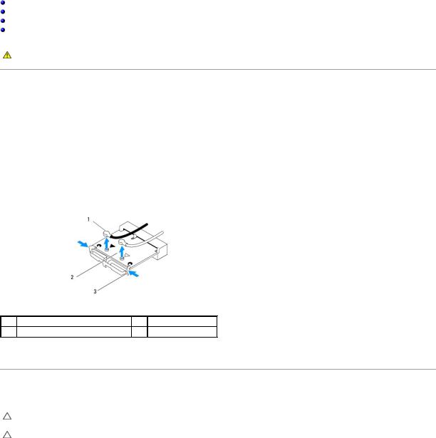
1 |
antenna cables (2) |
2 |
WLAN card |
3clips (2)
6.Lift the card away from the system board connector.
Replacing the WLAN Card
CAUTION: The connectors are keyed to ensure correct insertion. Use of excessive force may damage the connectors.
CAUTION: To avoid damage to the WLAN card, ensure that there are no cables under the card. Also, ensure to remove the antenna cables from under the card.
1.Follow the instructions in Before You Begin.
2.Connect the appropriate antenna cables to the WLAN card you are installing. The WLAN card has two triangles on the label (black and white): • Connect the black cable to the connector marked with a black triangle.
• Connect the white cable to the connector marked with a white triangle.
3.Align the notch on the WLAN card with the tab in the connector slot.
4.Insert the WLAN card at a 45-degree angle into the system board connector.
5.Press down on the WLAN card until it clicks in place.

6.Replace the shield (see Replacing the Shield).
7.Replace the computer cover (see Replacing the Computer Cover).
Removing the RF Module
WARNING: Before working inside your computer, read the safety information that shipped with your computer. For additional safety best practices information, see the Regulatory Compliance Homepage at www.dell.com/regulatory_compliance.
1.Follow the instructions in Before You Begin.
2.Remove the computer cover (see Removing the Computer Cover).
3.Remove the shield (see Removing the Shield).
4.Remove the stand (see Removing the Stand).
5.Remove the back I/O panel (see Removing the Back I/O Panel).
6.Remove the processor fan (see Removing the Processor Fan).
7.Remove the right speaker (see Removing the Right Speaker)
8.Remove the optical drive (see Removing the Optical Drive).
9.Remove the screw securing the radio frequency (RF) module, flip the module and disconnect the RF module cable.
1 |
RF module cable |
2 |
RF module |
3 screw
Replacing the RF Module
1.Follow the instructions in Before You Begin.
2.To install the RF module, connect the RF module cable.

3.Flip the RF module and align the screw hole on the RF module with the screw hole on the chassis.
4.Replace the screw that secures the RF module.
5.Replace the optical drive (see Replacing the Optical Drive).
6.Replace the right speaker (see Replacing the Right Speaker).
7.Replace the processor fan (see Replacing the Processor Fan).
8.Replace the back I/O panel (see Replacing the Back I/O Panel).
9.Replace the stand (see Replacing the Stand).
10.Replace the shield (see Replacing the Shield).
11.Replace the computer cover (see Replacing the Computer Cover).
Back to Contents Page
Back to Contents Page
Battery
Dell Studio One 19/1909 Service Manual
Removing the Battery
Replacing the Battery
WARNING: Before working inside your computer, read the safety information that shipped with your computer. For additional safety best practices information, see the Regulatory Compliance Homepage at www.dell.com/regulatory_compliance.
WARNING: A new battery can explode if it is incorrectly installed. Replace the battery only with the same or equivalent type recommended by the manufacturer. Discard used batteries according to the manufacturer's instructions.
Removing the Battery
1.Record all the screens in system setup (see System Setup) so that you can restore the correct settings in step 7.
2.Follow the procedures in Before You Begin.
3.Remove the computer cover (see Removing the Computer Cover).
4.Remove the shield (see Removing the Shield).
5.Disconnect the cables to the connectors HDD_POWER and SATA_1 (see System Board Components).
6.Locate the battery socket on the system board (see System Board Components).
CAUTION: If you pry the battery out of its socket with a blunt object, be careful not to touch the system board with the object. Ensure that the object is inserted between the battery and the socket before you attempt to pry out the battery. Otherwise, you may damage the system board by prying off the socket or by breaking circuit traces on the system board.
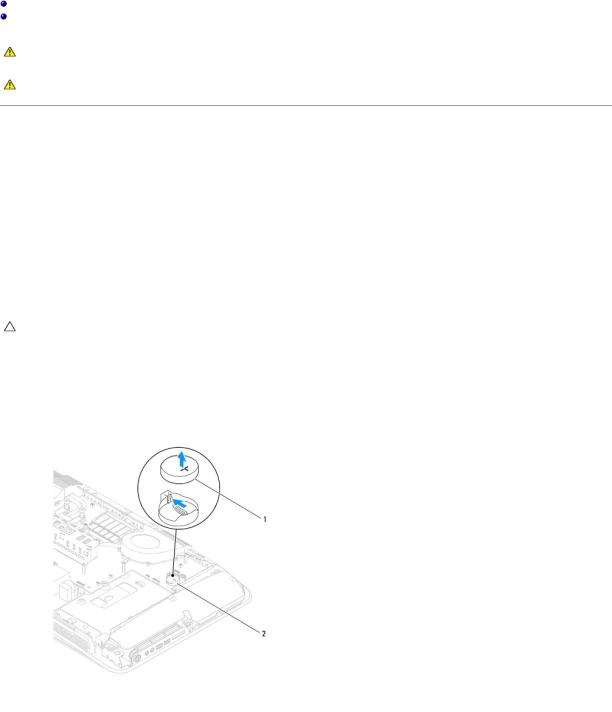
7.Carefully press the battery release lever away from the battery and the battery will pop out.
8.Remove the battery from the system and properly dispose of the battery.
1 |
coin-cell battery |
2 |
battery socket |
|
|
|
|
|
|
|
|
|
|
|

Replacing the Battery
1.Follow the procedures in Before You Begin.
2.Insert the new battery into the socket with the side labeled "+" facing up and then snap the battery into place.
3.Reconnect the cables to the connectors HDD_POWER and SATA_1 (see System Board Components).
4.Replace the shield (see Replacing the Shield).
5.Replace the computer cover (see Replacing the Computer Cover).
6.Connect your computer and devices to electrical outlets, and then turn them on.
7.Enter system setup (see System Setup) and restore the settings you recorded in step 1.
Back to Contents Page
Back to Contents Page
Computer Cover
Dell Studio One 19/1909 Service Manual
Removing the Computer Cover
Replacing the Computer Cover
WARNING: Before working inside your computer, read the safety information that shipped with your computer. For additional safety best practices information, see the Regulatory Compliance Homepage at www.dell.com/regulatory_compliance.
WARNING: To guard against electrical shock, always unplug your computer from the electrical outlet before removing the computer cover.
CAUTION: Ensure that sufficient space exists to support the system with the computer cover removed—at least 30 cm (1 ft.) of desk top space.
Removing the Computer Cover
1. Follow the procedures in Before You Begin.
CAUTION: Before opening your computer, ensure that you place the computer on a soft cloth or clean surface to avoid any scratches on the display.
2.Place the computer face down on a flat surface.
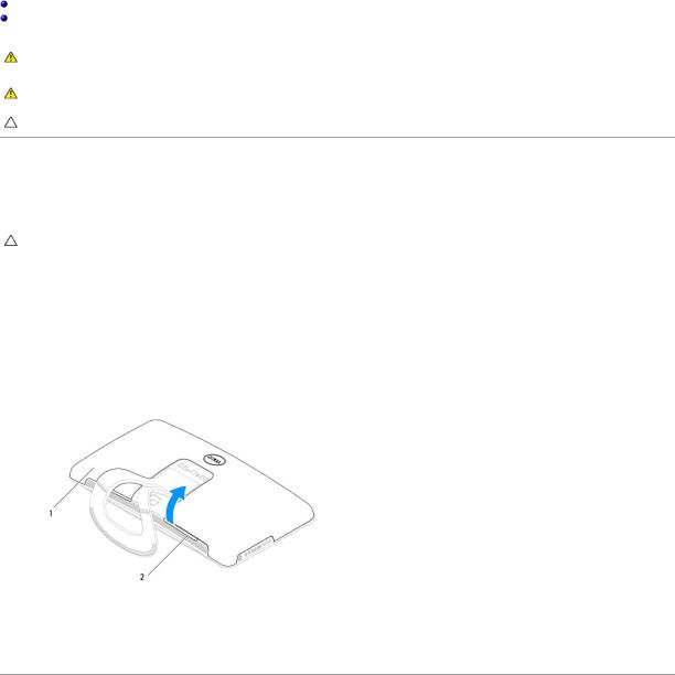
3.Starting at the groove at the bottom of the computer cover, use your fingers to separate the computer cover from the computer by lifting the insides of the computer cover.
4.Work around the computer cover and gently ease the computer cover away from the computer.
1 |
computer cover |
2 |
groove |
|
|
|
|
5. Lift the computer cover away from the computer and place it aside in a secure location.
Replacing the Computer Cover
1.Follow the procedures in Before You Begin.
2.Position the computer cover over the computer.
3.Gently ease the pins into the holes on the shield.
4.Press down and push the computer cover along the edges until it snaps into place.
5.Connect your computer and all attached devices to electrical outlets, and turn them on.

Back to Contents Page
Back to Contents Page
Support Assembly
Dell Studio One 19/1909 Service Manual
Removing the Support Assembly
Replacing the Support Assembly
WARNING: Before working inside your computer, read the safety information that shipped with your computer. For additional safety best practices information, see the Regulatory Compliance Homepage at www.dell.com/regulatory_compliance.
CAUTION: To avoid electrostatic discharge, ground yourself by using a wrist grounding strap or by periodically touching an unpainted metal surface (such as the computer stand).
Removing the Support Assembly
1.Follow the instructions in Before You Begin.
2.Remove the hard drive (see Removing the Hard Drive).
3.Remove the power supply unit (see Removing the Power Supply Unit).
4.Remove the optical drive (see Removing the Optical Drive).
5.Remove the side I/O panel (see Removing the Side I/O Panel).
6.Remove the inverter (see Removing the Inverter).
7.Remove the system board (see Removing the System Board).
8.Remove the fourteen screws that secure the support assembly to the LCD panel.
1 |
screws (14) |
2 |
support assembly |
|
|
|
|
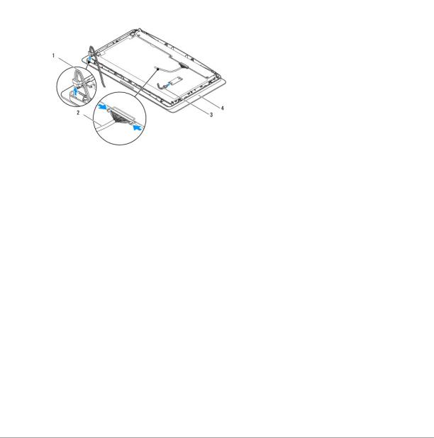
9. Disconnect the following cables from the LCD panel:
•LVDS cable from LVDS connector
•touch pad cable from the touch pad connector
•touch panel cable from the touch panel module
|
1 |
touch pad cable |
2 |
LVDS cable |
|
|
|
|
|
|
|
|
3 |
touch panel cable |
4 |
LCD panel |
|
|
|
|
|
|
|
Replacing the Support Assembly
1.Follow the instructions in Before You Begin.
2.Reconnect the following cables to the LCD panel: • LVDS cable from LVDS connector
• touch pad cable from the touch pad connector • touch panel cable from the touch panel module
3.Replace the fourteen screws that secure the support assembly to the LCD panel.
4.Replace the hard drive (see Replacing the Hard Drive).
5.Replace the power supply unit (see Replacing the Power Supply Unit).
6.Replace the optical drive (see Replacing the Optical Drive).
7.Replace the inverter (see Replacing the Inverter).
8.Replace the side I/O panel (see Replacing the Side I/O Panel).
9.Replace the system board (see Replacing the System Board).
Back to Contents Page
Back to Contents Page
Drives
Dell Studio One 19/1909 Service Manual
Removing the Hard Drive
Replacing the Hard Drive
Removing the Optical Drive
Replacing the Optical Drive
WARNING: Before working inside your computer, read the safety information that shipped with your computer. For additional safety best practices information, see the Regulatory Compliance Homepage at www.dell.com/regulatory_compliance.
Removing the Hard Drive
1.Follow the procedures in Before You Begin.
2.Remove the computer cover (see Removing the Computer Cover).
3.Remove the shield (see Removing the Shield).
4.Loosen the two captive screws securing the hard drive carrier to the chassis.
5.Slide the hard drive towards you and lift it away from the chassis.
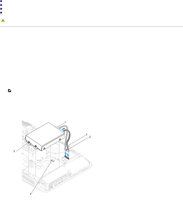
6.Disconnect the hard drive connector from the hard drive.
NOTE: If you are not replacing the hard drive at this time, disconnect the other end of the data cable from the connector (SATA_1) and power cable from the connector (HDD_POWER) on the system board and set it aside.
7. Lift the hard drive carrier out of the chassis.
1 |
hard drive connector |
2 |
hard drive data cable |
|
|
|
|
3 |
hard drive power cable |
4 |
grooves (2) |
|
|
|
|
5 |
captive screws (2) |
|
|
|
|
|
|
8. Remove the four screws securing the hard drive to the hard drive carrier.
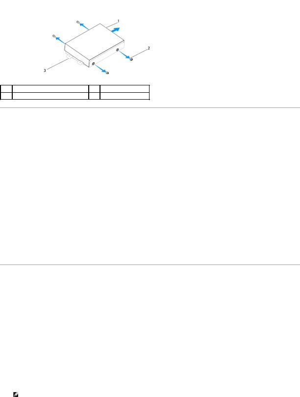
1 |
hard drive |
2 |
screws (4) |
3 hard drive carrier
Replacing the Hard Drive
1.Follow the procedures in Before You Begin.
2.Prepare the new hard drive for installation and check the documentation that accompanied the drive to verify that the drive is configured for your computer.
3.Align the screws holes on the hard drive with the screw holes on the hard drive carrier.
4.Replace the four screws that secure the hard drive to the hard drive carrier.
5.Reconnect the hard drive connector to the hard drive.
6.Slide the hard drive carrier into the grooves in the chassis.
7.Align the screw holes on the hard drive carrier with the screw holes on the chassis.
8.Tighten the two captive screws that secures the hard drive carrier to the chassis.
9.Replace the shield (see Replacing the Shield).
10.Replace the computer cover (see Replacing the Computer Cover).
Removing the Optical Drive
1.Follow the procedures in Before You Begin.
2.Remove the computer cover (see Removing the Computer Cover).
3.Remove the shield (see Removing the Shield).
4.Remove the stand (see Removing the Stand).
5.Remove the back I/O panel (see Removing the Back I/O Panel).
6.Remove the processor fan (see Removing the Processor Fan).
7.Remove the right speaker (see Removing the Right Speaker).
8.Disconnect the optical drive connector.
NOTE: If you are not replacing the optical drive at this time, disconnect the other end of the data cable (SATA_2) and power cable (ODD_POWER) from the system board and set it aside.
9. Remove the three screws securing the optical drive carrier to the chassis and slide the optical drive carrier out of the computer.
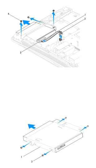
1 |
optical drive data cable |
2 |
optical drive power cable |
|
|
|
|
3 |
optical drive connector |
4 |
screws (3) |
|
|
|
|
10.Remove the four screws securing the optical drive to the optical drive carrier.
11.Slide the optical drive out of the optical drive carrier.
1 |
optical drive carrier |
2 |
screws (4) |
|
|
|
|
|
|
|
|
|
|
|
Replacing the Optical Drive
1.Follow the procedures in Before You Begin.
2.Prepare the optical drive for installation and check the documentation that accompanied the drive to verify that the drive is configured for your computer.
3.Slide the drive into the optical drive carrier.
4.Align the screw holes on the optical drive with the screw holes on the optical drive carrier, and replace the four screws that secure the optical drive.
5.Align the screw holes on the optical drive carrier with the screw holes on the chassis, and replace the three screws that secure the optical drive.
6.Reconnect the optical drive connector.
7.Replace the right speaker (see Replacing the Right Speaker).
8.Replace the processor fan (see Replacing the Processor Fan).

9.Replace the back I/O panel (see Replacing the Back I/O Panel).
10.Replace the stand (see Replacing the Stand).
11.Replace the shield (see Replacing the Shield).
12.Replace the computer cover (see Replacing the Computer Cover).
Back to Contents Page
 Loading...