


 Loading...
Inspiron 17/17R
Owner’s Manual
Computer model: Inspiron 3721/5721
Regulatory model: P17E
Regulatory type: P17E001

Notes, Cautions, and Warnings
NOTE: A NOTE indicates important information that helps you make better use of your computer.
CAUTION: A CAUTION indicates potential damage to hardware or loss of data if instructions are not followed.
 WARNING: A WARNING indicates a potential for property damage, personal injury, or death.
____________________
© 2012 Dell Inc.
Trademarks used in this text: Dell™, the DELL logo, and Inspiron™ are trademarks of Dell Inc.; Microsoft®, Windows®, and the Windows start button logo are either trademarks or registered trademarks of Microsoft Corporation in the United States and/or other countries; Bluetooth® is a registered trademark owned by Bluetooth SIG, Inc. and is used by Dell under license.
2012 - 12 |
Rev. A00 |
Contents
Before You Begin . . . . . . . . . . . . . . . . . . . . . . . . |
. . . |
9 |
Turn Off Your Computer and Connected Devices. . |
. . . |
9 |
Safety Instructions. . . . . . . . . . . . . . . . . . . . . . . |
. . |
10 |
Recommended Tools. . . . . . . . . . . . . . . . . . . . . |
. . |
10 |
After Working Inside Your Computer . . . . . . . . |
. . |
11 |
Removing the Battery . . . . . . . . . . . . . . . . . . . . |
. . |
12 |
Procedure . . . . . . . . . . . . . . . . . . . . . . . . . . . . |
. . |
12 |
Replacing the Battery . . . . . . . . . . . . . . . . . . . . |
. . |
13 |
Procedure . . . . . . . . . . . . . . . . . . . . . . . . . . . . |
. . |
13 |
Removing the Optical Drive . . . . . . . . . . . . . . . |
. . |
14 |
Prerequisites. . . . . . . . . . . . . . . . . . . . . . . . . . . |
. . |
14 |
Procedure . . . . . . . . . . . . . . . . . . . . . . . . . . . . |
. . |
14 |
Replacing the Optical Drive . . . . . . . . . . . . . . . |
. . |
16 |
Procedure . . . . . . . . . . . . . . . . . . . . . . . . . . . . |
. . |
16 |
Postrequisites . . . . . . . . . . . . . . . . . . . . . . . . . . |
. . |
16 |
Removing the Keyboard . . . . . . . . . . . . . . . . . . |
. . |
17 |
Prerequisites. . . . . . . . . . . . . . . . . . . . . . . . . . . |
. . |
17 |
Procedure . . . . . . . . . . . . . . . . . . . . . . . . . . . . |
. . |
17 |
Replacing the Keyboard . . . . . . . . . . . . . . . . . . |
. . |
19 |
Procedure . . . . . . . . . . . . . . . . . . . . . . . . . . . . |
. . |
19 |
Postrequisites . . . . . . . . . . . . . . . . . . . . . . . . . . |
. . |
19 |
Removing the Base Cover . . . . . . . . . . . . . . . . . |
. . |
20 |
Prerequisites. . . . . . . . . . . . . . . . . . . . . . . . . . . |
. . |
20 |
Procedure . . . . . . . . . . . . . . . . . . . . . . . . . . . . |
. . |
20 |
Contents | 3
Replacing the Base Cover . . . . . . . . . . . . . . . . . . . 21
Procedure . . . . . . . . . . . . . . . . . . . . . . . . . . . . . . 21 Postrequisites . . . . . . . . . . . . . . . . . . . . . . . . . . . . 21
Removing the Memory Module(s). . . . . . . . . . . . . 22
Prerequisites. . . . . . . . . . . . . . . . . . . . . . . . . . . . . 22 Procedure . . . . . . . . . . . . . . . . . . . . . . . . . . . . . . 22
Replacing the Memory Module(s). . . . . . . . . . . . . 23
Procedure . . . . . . . . . . . . . . . . . . . . . . . . . . . . . . 23 Postrequisites . . . . . . . . . . . . . . . . . . . . . . . . . . . . 23
Removing the Hard Drive . . . . . . . . . . . . . . . . . . . 24
Prerequisites. . . . . . . . . . . . . . . . . . . . . . . . . . . . . 24 Procedure . . . . . . . . . . . . . . . . . . . . . . . . . . . . . . 25
Replacing the Hard Drive. . . . . . . . . . . . . . . . . . . . 27
Procedure . . . . . . . . . . . . . . . . . . . . . . . . . . . . . . 27 Postrequisites . . . . . . . . . . . . . . . . . . . . . . . . . . . . 27
Removing the Coin-Cell Battery. . . . . . . . . . . . . . 28
Prerequisites. . . . . . . . . . . . . . . . . . . . . . . . . . . . . 28 Procedure . . . . . . . . . . . . . . . . . . . . . . . . . . . . . . 28
Replacing the Coin-Cell Battery . . . . . . . . . . . . . . 29
Procedure . . . . . . . . . . . . . . . . . . . . . . . . . . . . . . 29 Postrequisites . . . . . . . . . . . . . . . . . . . . . . . . . . . . 29
Removing the Palm-Rest. . . . . . . . . . . . . . . . . . . . 30
Prerequisites. . . . . . . . . . . . . . . . . . . . . . . . . . . . . 30 Procedure . . . . . . . . . . . . . . . . . . . . . . . . . . . . . . 30
Replacing the Palm-Rest . . . . . . . . . . . . . . . . . . . . 33
Procedure . . . . . . . . . . . . . . . . . . . . . . . . . . . . . . 33 Postrequisites . . . . . . . . . . . . . . . . . . . . . . . . . . . . 33
4 | Contents
Removing the Wireless Mini-Card . . . . . . . . . . . . |
34 |
Prerequisites. . . . . . . . . . . . . . . . . . . . . . . . . . . . . |
34 |
Procedure . . . . . . . . . . . . . . . . . . . . . . . . . . . . . . |
34 |
Replacing the Wireless Mini-Card . . . . . . . . . . . . |
36 |
Procedure . . . . . . . . . . . . . . . . . . . . . . . . . . . . . . |
36 |
Postrequisites . . . . . . . . . . . . . . . . . . . . . . . . . . . . |
36 |
Removing the I/O Board . . . . . . . . . . . . . . . . . . . . |
37 |
Prerequisites. . . . . . . . . . . . . . . . . . . . . . . . . . . . . |
37 |
Procedure . . . . . . . . . . . . . . . . . . . . . . . . . . . . . . |
37 |
Replacing the I/O Board . . . . . . . . . . . . . . . . . . . . |
38 |
Procedure . . . . . . . . . . . . . . . . . . . . . . . . . . . . . . |
38 |
Postrequisites . . . . . . . . . . . . . . . . . . . . . . . . . . . . |
38 |
Removing the System Board . . . . . . . . . . . . . . . . . |
39 |
Prerequisites. . . . . . . . . . . . . . . . . . . . . . . . . . . . . |
39 |
Procedure . . . . . . . . . . . . . . . . . . . . . . . . . . . . . . |
40 |
Replacing the System Board . . . . . . . . . . . . . . . . . |
43 |
Procedure . . . . . . . . . . . . . . . . . . . . . . . . . . . . . . |
43 |
Postrequisites . . . . . . . . . . . . . . . . . . . . . . . . . . . . |
44 |
Removing the Fan . . . . . . . . . . . . . . . . . . . . . . . . . |
45 |
Prerequisites. . . . . . . . . . . . . . . . . . . . . . . . . . . . . |
45 |
Procedure . . . . . . . . . . . . . . . . . . . . . . . . . . . . . . |
46 |
Replacing the Fan. . . . . . . . . . . . . . . . . . . . . . . . . . |
47 |
Procedure . . . . . . . . . . . . . . . . . . . . . . . . . . . . . . |
47 |
Postrequisites . . . . . . . . . . . . . . . . . . . . . . . . . . . . |
47 |
Removing the Cooling Assembly . . . . . . . . . . . . . |
48 |
Prerequisites. . . . . . . . . . . . . . . . . . . . . . . . . . . . . |
48 |
Procedure . . . . . . . . . . . . . . . . . . . . . . . . . . . . . . |
49 |
Contents | 5
Replacing the Cooling Assembly . . . . . . . . . . . . . |
50 |
Procedure . . . . . . . . . . . . . . . . . . . . . . . . . . . . . . |
50 |
Postrequisites . . . . . . . . . . . . . . . . . . . . . . . . . . . . |
50 |
Removing the Hard-Drive Interposer Board . . . . 51 |
|
Prerequisites. . . . . . . . . . . . . . . . . . . . . . . . . . . . . |
51 |
Procedure . . . . . . . . . . . . . . . . . . . . . . . . . . . . . . |
52 |
Replacing the Hard-Drive Interposer Board . . . . 53 |
|
Procedure . . . . . . . . . . . . . . . . . . . . . . . . . . . . . . |
53 |
Postrequisites . . . . . . . . . . . . . . . . . . . . . . . . . . . . |
53 |
Removing the Speakers . . . . . . . . . . . . . . . . . . . . . |
54 |
Prerequisites. . . . . . . . . . . . . . . . . . . . . . . . . . . . . |
54 |
Procedure . . . . . . . . . . . . . . . . . . . . . . . . . . . . . . |
55 |
Replacing the Speakers . . . . . . . . . . . . . . . . . . . . . |
56 |
Procedure . . . . . . . . . . . . . . . . . . . . . . . . . . . . . . |
56 |
Postrequisites . . . . . . . . . . . . . . . . . . . . . . . . . . . . |
56 |
Removing the Display Assembly . . . . . . . . . . . . . . |
57 |
Prerequisites. . . . . . . . . . . . . . . . . . . . . . . . . . . . . |
57 |
Procedure . . . . . . . . . . . . . . . . . . . . . . . . . . . . . . |
58 |
Replacing the Display Assembly . . . . . . . . . . . . . . |
59 |
Procedure . . . . . . . . . . . . . . . . . . . . . . . . . . . . . . |
59 |
Postrequisites . . . . . . . . . . . . . . . . . . . . . . . . . . . . |
59 |
Removing the Display Bezel . . . . . . . . . . . . . . . . . |
60 |
Prerequisites. . . . . . . . . . . . . . . . . . . . . . . . . . . . . |
60 |
Procedure . . . . . . . . . . . . . . . . . . . . . . . . . . . . . . |
61 |
Replacing the Display Bezel . . . . . . . . . . . . . . . . . |
62 |
Procedure . . . . . . . . . . . . . . . . . . . . . . . . . . . . . . |
62 |
Postrequisites . . . . . . . . . . . . . . . . . . . . . . . . . . . . |
62 |
6 | Contents
Removing the Display Hinges . . . . . . . . . . . . . . . . |
63 |
Prerequisites. . . . . . . . . . . . . . . . . . . . . . . . . . . . . |
63 |
Procedure . . . . . . . . . . . . . . . . . . . . . . . . . . . . . . |
64 |
Replacing the Display Hinges . . . . . . . . . . . . . . . . |
65 |
Procedure . . . . . . . . . . . . . . . . . . . . . . . . . . . . . . |
65 |
Postrequisites . . . . . . . . . . . . . . . . . . . . . . . . . . . . |
65 |
Removing the Display Panel . . . . . . . . . . . . . . . . . |
66 |
Prerequisites. . . . . . . . . . . . . . . . . . . . . . . . . . . . . |
66 |
Procedure . . . . . . . . . . . . . . . . . . . . . . . . . . . . . . |
67 |
Replacing the Display Panel . . . . . . . . . . . . . . . . . |
69 |
Procedure . . . . . . . . . . . . . . . . . . . . . . . . . . . . . . |
69 |
Postrequisites . . . . . . . . . . . . . . . . . . . . . . . . . . . . |
69 |
Removing the Camera Module . . . . . . . . . . . . . . . |
70 |
Prerequisites. . . . . . . . . . . . . . . . . . . . . . . . . . . . . |
70 |
Procedure . . . . . . . . . . . . . . . . . . . . . . . . . . . . . . |
71 |
Replacing the Camera Module . . . . . . . . . . . . . . . |
72 |
Procedure . . . . . . . . . . . . . . . . . . . . . . . . . . . . . . |
72 |
Postrequisites . . . . . . . . . . . . . . . . . . . . . . . . . . . . |
72 |
Removing the Power-Adapter Port . . . . . . . . . . . |
73 |
Prerequisites. . . . . . . . . . . . . . . . . . . . . . . . . . . . . |
73 |
Procedure . . . . . . . . . . . . . . . . . . . . . . . . . . . . . . |
74 |
Replacing the Power-Adapter Port . . . . . . . . . . . |
75 |
Procedure . . . . . . . . . . . . . . . . . . . . . . . . . . . . . . |
75 |
Postrequisites . . . . . . . . . . . . . . . . . . . . . . . . . . . . |
75 |
Flashing the BIOS . . . . . . . . . . . . . . . . . . . . . . . . . . |
76 |
Contents | 7
8 | Contents

Before You Begin
Turn Off Your Computer and Connected Devices
CAUTION: To avoid losing data, save and close all open files and exit all open programs before you turn off your computer.
1Save and close all open files and exit all open programs.
2Shut down your computer.
Windows 8:
a Point your mouse pointer to the upper-right or lower-right corner of the screen to open the Charms sidebar.
b In the Charms sidebar, click Settings→ Power→ Shut down.
Windows 7:
Click Start  and click Shut down.
Microsoft Windows shuts down and then the computer turns off.
NOTE: If you are using a different operating system, see the documentation of your operating system for shut-down instructions.
3Disconnect your computer and all attached devices from their electrical outlets.
4Disconnect all telephone cables, network cables, and attached devices from your computer.
5After you unplug all the cables from the computer, press and hold the power button for 5 seconds to ground the system board.
Before You Begin |
| |
9 |

Safety Instructions
Use the following safety guidelines to protect your computer from potential damage and ensure your personal safety.
WARNING: Before working inside your computer, read the safety information that shipped with your computer. For additional safety best practices information, see the Regulatory Compliance Homepage at dell.com/regulatory_compliance.
WARNING: Disconnect all power sources before opening the computer cover or panels. After you finish working inside the computer, replace all covers, panels, and screws before connecting to the power source.
CAUTION: To avoid damaging the computer, ensure that the work surface is flat and clean.
CAUTION: To avoid damaging the components and cards, handle them by their edges and avoid touching pins and contacts.
CAUTION: Only a certified service technician is authorized to remove the computer cover and access any of the components inside the computer. See the safety instructions for complete information about safety precautions, working inside your computer, and protecting against electrostatic discharge.
CAUTION: Before touching anything inside your computer, ground yourself by touching an unpainted metal surface, such as the metal at the back of the computer. While you work, periodically touch an unpainted metal surface to dissipate static electricity, which could harm internal components.
CAUTION: When you disconnect a cable, pull on its connector or on its pull-tab, not on the cable itself. Some cables have connectors with locking tabs or thumb-screws that you must disengage before disconnecting the cable.
When disconnecting cables, keep them evenly aligned to avoid bending any connector pins. When connecting cables, ensure that the connectors and ports are correctly oriented and aligned.
CAUTION: To disconnect a network cable, first unplug the cable from your computer and then unplug the cable from the network device.
CAUTION: Press and eject any installed card from the media-card reader.
Recommended Tools
The procedures in this document may require the following tools:
•Phillips screwdriver
•Plastic scribe
10 |
| |
Before You Begin |
After Working Inside Your Computer
After you complete the replacement procedures, ensure the following:
•Replace all screws and ensure that no stray screws remain inside your computer.
•Connect any external devices, cables, cards, and any other part(s) you removed before working on your computer.
•Connect your computer and all attached devices to their electrical outlets.
CAUTION: Before turning on your computer, replace all screws and ensure that no stray screws remain inside the computer. Failure to do so may damage your computer.
After Working Inside Your Computer |
| |
11 |
Removing the Battery
WARNING: Before working inside your computer, read the safety information that shipped with your computer and follow the steps in "Before You Begin" on page 9. After working inside your computer, follow the instructions in "After Working Inside Your Computer" on page 11. For additional safety best practices information, see the Regulatory Compliance Homepage at dell.com/regulatory_compliance.
Procedure
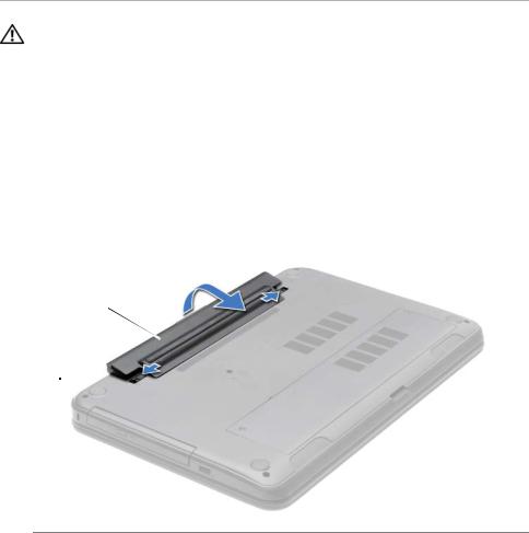
1Close the display and turn the computer over.
2Slide the battery latches to the unlock position. You hear a click when the battery is unlocked.
3Lift and remove the battery off the computer base.
2
1
1 |
battery latches (2) |
2 |
battery |
|
|
|
|
12 |
| |
Removing the Battery |

Replacing the Battery
WARNING: Before working inside your computer, read the safety information that shipped with your computer and follow the steps in "Before You Begin" on page 9. After working inside your computer, follow the instructions in "After Working Inside Your Computer" on page 11. For additional safety best practices information, see the Regulatory Compliance Homepage at dell.com/regulatory_compliance.
Procedure
Align the tabs on the battery with the slots on the battery bay and snap the battery into place.
Replacing the Battery |
| |
13 |
Removing the Optical Drive
WARNING: Before working inside your computer, read the safety information that shipped with your computer and follow the steps in "Before You Begin" on page 9. After working inside your computer, follow the instructions in "After Working Inside Your Computer" on page 11. For additional safety best practices information, see the Regulatory Compliance Homepage at dell.com/regulatory_compliance.
Prerequisites
Remove the battery. See "Removing the Battery" on page 12.
Procedure
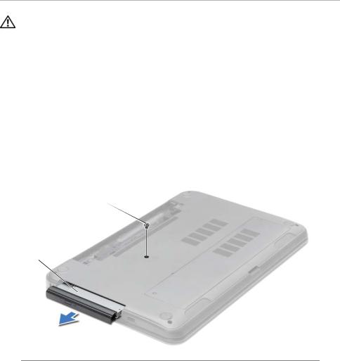
1Remove the screw that secures the optical-drive assembly to the computer base.
2Using your fingertips, slide the optical-drive assembly out of the optical-drive bay.
2
1
1 |
optical-drive assembly |
2 |
screw |
|
|
|
|
14 |
| |
Removing the Optical Drive |
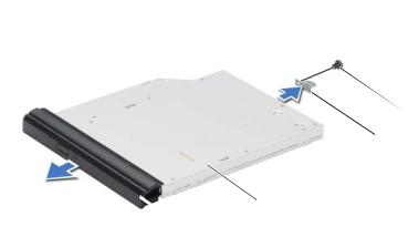
3Remove the screw that secures the optical-drive bracket to the optical-drive assembly and remove the optical-drive bracket.
4Carefully pull the optical-drive bezel and remove it from the optical drive.
 4
4
 3
3
|
|
|
2 |
|
|
1 |
|
|
|
|
|
1 |
optical-drive bezel |
2 |
optical drive |
|
|
|
|
3 |
optical-drive bracket |
4 |
screw |
|
|
|
|
Removing the Optical Drive |
| |
15 |

Replacing the Optical Drive
WARNING: Before working inside your computer, read the safety information that shipped with your computer and follow the steps in "Before You Begin" on page 9. After working inside your computer, follow the instructions in "After Working Inside Your Computer" on page 11. For additional safety best practices information, see the Regulatory Compliance Homepage at dell.com/regulatory_compliance.
Procedure
1Align the tabs on the optical-drive bezel with the slots on the optical drive and snap the optical-drive bezel into place.
2Align the screw hole on the optical-drive bracket with the screw hole on
the optical-drive assembly and replace the screw that secures the optical-drive bracket to the optical-drive assembly.
3Slide the optical-drive assembly into the optical-drive bay and ensure that the screw hole on the optical-drive bracket aligns with the screw hole
on computer base.
4Replace the screw that secures the optical-drive assembly to the computer base.
Postrequisites
Replace the battery. See "Replacing the Battery" on page 13.
16 |
| |
Replacing the Optical Drive |

Removing the Keyboard
WARNING: Before working inside your computer, read the safety information that shipped with your computer and follow the steps in "Before You Begin" on page 9. After working inside your computer, follow the instructions in "After Working Inside Your Computer" on page 11. For additional safety best practices information, see the Regulatory Compliance Homepage at dell.com/regulatory_compliance.
Prerequisites
Remove the battery. See "Removing the Battery" on page 12.
Procedure
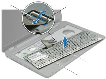
1Open the display as far as possible.
2Using a plastic scribe, pry the keyboard from the tabs on the palm-rest.
1
 2
2
 3
3
1 |
tabs (4) |
2 |
plastic scribe |
3keyboard
Removing the Keyboard |
| |
17 |
3Turn the keyboard over and place it on the palm-rest.
4Lift the connector latch and disconnect the keyboard cable from the keyboard-cable connector.
5Lift the keyboard off the palm-rest.
1
 2
2
|
|
|
3 |
|
|
|
4 |
|
|
|
|
1 |
keyboard cable |
2 |
connector latch |
|
|
|
|
3 |
keyboard |
4 |
palm-rest |
|
|
|
|
18 |
| |
Removing the Keyboard |

Replacing the Keyboard
WARNING: Before working inside your computer, read the safety information that shipped with your computer and follow the steps in "Before You Begin" on page 9. After working inside your computer, follow the instructions in "After Working Inside Your Computer" on page 11. For additional safety best practices information, see the Regulatory Compliance Homepage at dell.com/regulatory_compliance.
Procedure
1Slide the keyboard cable into the keyboard-cable connector and press down on the connector latch to secure the cable.
2Slide the tabs at the bottom of the keyboard into the slots on the palm-rest and place the keyboard on the palm-rest.
3Gently press around the edges of the keyboard to secure the keyboard under the tabs on the palm-rest.
4Replace the screws that secure the keyboard to the computer base.
Postrequisites
Replace the battery. See "Replacing the Battery" on page 13.
Replacing the Keyboard |
| |
19 |
Removing the Base Cover
WARNING: Before working inside your computer, read the safety information that shipped with your computer and follow the steps in "Before You Begin" on page 9. After working inside your computer, follow the instructions in "After Working Inside Your Computer" on page 11. For additional safety best practices information, see the Regulatory Compliance Homepage at dell.com/regulatory_compliance.
Prerequisites
Remove the battery. See "Removing the Battery" on page 12.
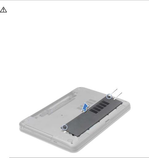
Procedure
1Loosen the captive screws that secure the base cover to the computer base.
2Using your fingertips, lift the base cover out of the slots on the computer base.
 1
1
 2
2
1 |
captive screws (2) |
2 |
base cover |
|
|
|
|
20 |
| |
Removing the Base Cover |
Replacing the Base Cover
WARNING: Before working inside your computer, read the safety information that shipped with your computer and follow the steps in "Before You Begin" on page 9. After working inside your computer, follow the instructions in "After Working Inside Your Computer" on page 11. For additional safety best practices information, see the Regulatory Compliance Homepage at dell.com/regulatory_compliance.
Procedure
1Slide the tabs on the base cover into the slots on the computer base and snap the base cover into place.
2Tighten the captive screws that secure the base cover to the computer base.
Postrequisites
Replace the battery. See "Replacing the Battery" on page 13.
Replacing the Base Cover |
| |
21 |

Removing the Memory Module(s)
WARNING: Before working inside your computer, read the safety information that shipped with your computer and follow the steps in "Before You Begin" on page 9. After working inside your computer, follow the instructions in "After Working Inside Your Computer" on page 11. For additional safety best practices information, see the Regulatory Compliance Homepage at dell.com/regulatory_compliance.
Prerequisites
1Remove the battery. See "Removing the Battery" on page 12.
2Remove the base cover. See "Removing the Base Cover" on page 20.
Procedure
1Use your fingertips to carefully spread apart the securing-clips on each end of the memory-module connector until the memory module pops up.
2Remove the memory module from the memory-module connector.
3
2
1 
1 securing-clips (2) |
2 memory-module connector |
3memory module
22 |
| |
Removing the Memory Module(s) |

Replacing the Memory Module(s)
WARNING: Before working inside your computer, read the safety information that shipped with your computer and follow the steps in "Before You Begin" on page 9. After working inside your computer, follow the instructions in "After Working Inside Your Computer" on page 11. For additional safety best practices information, see the Regulatory Compliance Homepage at dell.com/regulatory_compliance.
Procedure
1Align the notch on the memory module with the tab on the memory-module connector.
2Slide the memory module firmly, at a 45-degree angle into the connector, and press the memory module down until it clicks into place.
NOTE: If you do not hear the click, remove the memory module and reinstall it.
Postrequisites
1Replace the base cover. See "Replacing the Base Cover" on page 21.
2Replace the battery. See "Replacing the Battery" on page 13.
Replacing the Memory Module(s) |
| |
23 |
Loading...