


QuickScan® QS6500/QS6500BT
Product Reference Guide
Datalogic Scanning, Inc.
959 Terry Street Eugene, Oregon 97402
Telephone: (541) 683-5700 Fax: (541) 345-7140
An Unpublished Work - All rights reserved. No part of the contents of this documentation or the procedures described therein may be reproduced or transmitted in any form or by any means without prior written permission of Datalogic Scanning, Inc. or its subsidiaries or affiliates ("Datalogic" or “Datalogic Scanning”).
Owners of Datalogic products are hereby granted a non-exclusive, revocable license to reproduce and transmit this documentation for the purchaser's own internal business purposes. Purchaser shall not remove or alter any proprietary notices, including copyright notices, contained in this documentation and shall ensure that all notices appear on any reproductions of the documentation.
Should future revisions of this manual be published, you can acquire printed versions by contacting your Datalogic representative. Electronic versions may either be downloadable from the Datalogic website (www.scanning.datalogic.com) or provided on appropriate media. If you visit our website and would like to make comments or suggestions about this or other Datalogic publications, please let us know via the "Contact Datalogic" page.
Disclaimer
Datalogic has taken reasonable measures to provide information in this manual that is complete and accurate, however, Datalogic reserves the right to change any specification at any time without prior notice. Datalogic is a registered trademark of Datalogic S.p.A. and the Datalogic logo is a trademark of Datalogic S.p.A. all licensed to Datalogic Scanning, Inc. All other trademarks and trade names referred to herein are property of their respective owners.
This product may be covered by one or more of the following patents: 6,293,467 • 6,612,495 • 6,705,527 •
Other Patents Pending

Table of Contents
Chapter 1 Getting Started......................................................... |
1-1 |
About This Manual ............................................................................ |
1-1 |
Manual Conventions .................................................................... |
1-2 |
Default Information ............................................................... |
1-2 |
Nomenclature .................................................................................. |
1-2 |
Symbologies .................................................................................... |
1-3 |
Linear Imager Settings ...................................................................... |
1-3 |
Return to Factory Defaults ................................................................. |
1-3 |
Chapter 2 Bluetooth Models...................................................... |
2-1 |
Linking an Imager with a Base Station ................................................. |
2-1 |
Unlinking ......................................................................................... |
2-2 |
Battery Charging .............................................................................. |
2-3 |
Paging the Imager ............................................................................ |
2-3 |
Chapter 3 General Features ...................................................... |
3-1 |
Double Read Timeout ........................................................................ |
3-1 |
Imager Timeout ............................................................................... |
3-3 |
Read Verification .............................................................................. |
3-4 |
LED and Beeper Indicators ................................................................. |
3-6 |
Power On Alert ........................................................................... |
3-6 |
LED Idle State ............................................................................ |
3-6 |
Good Read: When to Indicate ....................................................... |
3-7 |
Good Read Beep Control .............................................................. |
3-8 |
Good Read Beep Frequency ......................................................... |
3-8 |
Good Read Beep Length .............................................................. |
3-9 |
Good Read Beep Volume ........................................................... |
3-11 |
Scanning/Imaging Features ............................................................. |
3-12 |
Scan Mode .............................................................................. |
3-12 |
Stand Mode LED ....................................................................... |
3-14 |
Scan Illumination LED Timeout ................................................... |
3-14 |
Inverted Image Scan ................................................................ |
3-15 |
Global Features .............................................................................. |
3-16 |
Global Minimum Code Length ..................................................... |
3-16 |
Global Maximum Code Length............................................... |
3-17 |
Chapter 4 Interface Related Features |
.......................................4-1 |
Interface Selection ............................................................................ |
4-4 |
Interface Features ............................................................................ |
4-8 |
Global Interface Features ............................................................ |
4-8 |
RS-232 Interface Features ........................................................... |
4-9 |
Hardware Flow Control......................................................... |
4-11 |
Intercharacter Delay............................................................ |
4-11 |
Software Flow Control.......................................................... |
4-11 |
Product Reference Guide |
i |

Host Echo ........................................................................... |
4-14 |
Host Echo Quiet Interval....................................................... |
4-14 |
Signal Voltage: Normal/TTL................................................... |
4-14 |
RS-232 Invert ..................................................................... |
4-14 |
Beep on ASCII BEL............................................................... |
4-16 |
Beep on Not on File.............................................................. |
4-16 |
ACK NAK Options................................................................. |
4-16 |
ACK Character..................................................................... |
4-18 |
NAK Character..................................................................... |
4-19 |
Retry on ACK NAK Timeout ................................................... |
4-20 |
ACK NAK Timeout Value ....................................................... |
4-21 |
ACK NAK Retry Count........................................................... |
4-22 |
ACK NAK Error Handling ............................................................. |
4-23 |
Transmission Failure Indication.............................................. |
4-24 |
IBM-USB Interface Features ....................................................... |
4-25 |
IBM-USB Device usage ......................................................... |
4-25 |
IBM ......................................................................................... |
4-26 |
IBM Transmit Labels in Code 39 Format .................................. |
4-26 |
Keyboard Wedge/USB Keyboard .................................................. |
4-27 |
Wand Emulation ....................................................................... |
4-34 |
Supported Symbologies ........................................................ |
4-34 |
Wand Emulation Bar Code Format.......................................... |
4-34 |
Bar/Space Polarity ............................................................... |
4-35 |
Initial Polarity...................................................................... |
4-35 |
Signal Speed....................................................................... |
4-36 |
Transmit Trailing Noise......................................................... |
4-36 |
Transmit Leading Noise ........................................................ |
4-37 |
Symbology Conversion ......................................................... |
4-37 |
Chapter 5 Data Editing............................................................. |
5-1 |
Data Editing Overview ....................................................................... |
5-1 |
Please Keep In Mind... ................................................................. |
5-2 |
Prefix/Suffix.......................................................................... |
5-2 |
Preamble/Postamble .............................................................. |
5-5 |
Symbology, I.D. and Code Length............................................ |
5-8 |
Data Group Characters ......................................................... |
5-11 |
Case Conversion ....................................................................... |
5-14 |
Chapter 6 Symbologies ............................................................ |
6-1 |
UPC-A .............................................................................................. |
6-2 |
Disable/Enable UPC-A .................................................................. |
6-2 |
Checksum Transmission ............................................................... |
6-2 |
Expand UPC-A to EAN-13 ............................................................. |
6-2 |
Truncate Leading/Ending .............................................................. |
6-4 |
Code I.D. Selection ..................................................................... |
6-5 |
Example: Setting the UPC-A Code I.D....................................... |
6-5 |
UPC-A Data Group Characters ....................................................... |
6-7 |
UPC-A — continued ..................................................................... |
6-9 |
Add-ons ..................................................................................... |
6-9 |
UPC-E ............................................................................................ |
6-11 |
Disable/Enable UPC-E ................................................................ |
6-11 |
ii |
QuickScan® QS6500/QS6500BT |

Checksum Transmission ............................................................ |
6-11 |
Truncate/Expand ...................................................................... |
6-11 |
Truncate Leading/Ending ........................................................... |
6-13 |
Code I.D. Selection ................................................................... |
6-14 |
Example: Setting the UPC-E Code I.D. ................................... |
6-14 |
UPC-E Data Group Characters .................................................... |
6-16 |
Add-ons .................................................................................. |
6-18 |
EAN-13 ......................................................................................... |
6-20 |
Disable/Enable EAN-13 .............................................................. |
6-20 |
Checksum Transmission ............................................................ |
6-20 |
ISBN/ISSN .............................................................................. |
6-20 |
EAN-13 — continued ................................................................. |
6-22 |
ISBN ID Setting ....................................................................... |
6-22 |
Example: Setting the ISBN ID............................................... |
6-22 |
Truncate Leading/Ending ........................................................... |
6-24 |
Code I.D. Selection ................................................................... |
6-25 |
Example: Setting the EAN-13 Code I.D. ................................. |
6-25 |
EAN-13 Data Group Characters .................................................. |
6-27 |
Add-ons .................................................................................. |
6-29 |
EAN-8 ........................................................................................... |
6-31 |
Disable/Enable EAN-8 ............................................................... |
6-31 |
Checksum Transmission ............................................................ |
6-31 |
Truncate/Expand ...................................................................... |
6-32 |
Truncate Leading/Ending ........................................................... |
6-33 |
Code I.D. Selection ................................................................... |
6-34 |
Example: Setting the EAN-8 Code I.D. ................................... |
6-34 |
EAN-8 Data Group Characters .................................................... |
6-36 |
Add-ons .................................................................................. |
6-38 |
GTIN ............................................................................................. |
6-40 |
Disable/Enable GTIN ................................................................. |
6-40 |
Code I.D. Selection ................................................................... |
6-40 |
Example: Setting the GTIN Code I.D...................................... |
6-40 |
RSS-14 ......................................................................................... |
6-42 |
Disable/Enable RSS-14 .............................................................. |
6-42 |
Checksum Transmission ............................................................ |
6-42 |
UCC/EAN 128 Emulation ............................................................ |
6-42 |
Truncate Leading/Ending ........................................................... |
6-44 |
Code I.D. Selection ................................................................... |
6-45 |
Example: Setting the RSS-14 Code I.D. ................................. |
6-45 |
RSS-14 Data Group Characters .................................................. |
6-47 |
RSS Expanded ............................................................................... |
6-49 |
Disable/Enable RSS Expanded .................................................... |
6-49 |
UCC/EAN 128 Emulation ............................................................ |
6-49 |
Minimum/Maximum Code Length ................................................ |
6-50 |
Truncate Leading/Ending ........................................................... |
6-51 |
Code I.D. Selection ................................................................... |
6-52 |
Example: Setting the RSS Expanded Code I.D......................... |
6-52 |
RSS Expanded Data Group Characters ......................................... |
6-54 |
RSS Limited ................................................................................... |
6-56 |
Disable/Enable RSS Limited ....................................................... |
6-56 |
Checksum Transmission ............................................................ |
6-56 |
UCC/EAN 128 Emulation ............................................................ |
6-56 |
Product Reference Guide |
iii |

Truncate Leading/Ending ............................................................ |
6-58 |
Code I.D. Selection ................................................................... |
6-59 |
Example: Setting the RSS Limited Code I.D............................. |
6-59 |
RSS Limited Data Group Characters ............................................. |
6-61 |
Code 39 ......................................................................................... |
6-63 |
Disable/Enable Code 39 ............................................................. |
6-63 |
Checksum Verification ............................................................... |
6-63 |
Checksum Transmit ................................................................... |
6-63 |
Minimum/Maximum Code Length ................................................ |
6-65 |
Truncate Leading/Ending ............................................................ |
6-66 |
Code I.D. Selection ................................................................... |
6-67 |
Example: Setting the Code 39 Code I.D.................................. |
6-67 |
Code 39 Data Group Characters .................................................. |
6-69 |
Format .................................................................................... |
6-71 |
Append .................................................................................... |
6-71 |
Start/End Transmission .............................................................. |
6-71 |
Pharmacode 39 ............................................................................... |
6-73 |
Disable/Enable Pharmacode 39 ................................................... |
6-73 |
Leading ‘A’ ............................................................................... |
6-73 |
Minimum/Maximum Code Length ................................................ |
6-74 |
Truncate Leading/Ending ............................................................ |
6-75 |
Code I.D. Selection ................................................................... |
6-76 |
Example: Setting the Pharmacode 39 Code I.D........................ |
6-76 |
Pharmacode 39 Data Group Characters ........................................ |
6-78 |
Code 128 ....................................................................................... |
6-80 |
Disable/Enable Code 128 ........................................................... |
6-80 |
Checksum Verification ............................................................... |
6-80 |
Checksum Transmit ................................................................... |
6-80 |
Function Code Transmission ....................................................... |
6-80 |
Minimum/Maximum Code Length ................................................ |
6-82 |
Truncate Leading/Ending ............................................................ |
6-83 |
Code I.D. Selection ................................................................... |
6-84 |
Example: Setting the Code 128 Code I.D. ............................... |
6-84 |
Code 128 Data Group Characters ................................................ |
6-86 |
EAN-128 ........................................................................................ |
6-88 |
Format as EAN-128 ................................................................... |
6-88 |
Append .................................................................................... |
6-88 |
UCC/EAN-128 ID setting ............................................................ |
6-89 |
Interleaved 2 of 5 ........................................................................... |
6-90 |
Disable/Enable Interleaved 2 of 5 ................................................ |
6-90 |
Checksum Verification ............................................................... |
6-90 |
Checksum Transmit ................................................................... |
6-90 |
Fixed Length Control ................................................................. |
6-92 |
Minimum/Maximum Code Length ................................................ |
6-94 |
Truncate Leading/Ending ............................................................ |
6-95 |
Code I.D. Selection ................................................................... |
6-96 |
Example: Setting the Interleaved 2 of 5 Code I.D..................... |
6-96 |
Interleaved 2 of 5 Data Group Characters .................................... |
6-98 |
Industrial 2 of 5 ............................................................................ |
6-100 |
Disable/Enable Industrial 2 of 5 ................................................ |
6-100 |
Minimum/Maximum Code Length .............................................. |
6-101 |
Truncate Leading/Ending .......................................................... |
6-102 |
iv |
QuickScan® QS6500/QS6500BT |

Code I.D. Selection .................................................................. |
6-103 |
Example: Setting the Industrial 2 of 5 Code I.D...................... |
6-103 |
Industrial 2 of 5 Data Group Characters ...................................... |
6-105 |
Matrix 2 of 5 (Eur) ......................................................................... |
6-107 |
Disable/Enable Matrix 2 of 5 ..................................................... |
6-107 |
Checksum Verification .............................................................. |
6-107 |
Checksum Transmit ................................................................. |
6-107 |
Minimum/Maximum Code Length ............................................... |
6-109 |
Truncate Leading/Ending .......................................................... |
6-110 |
Code I.D. Selection .................................................................. |
6-111 |
Example: Setting the Matrix 2 of 5 Code I.D. ......................... |
6-111 |
Matrix 2 of 5 Data Group Characters .......................................... |
6-113 |
Codabar ....................................................................................... |
6-115 |
Disable/Enable Codabar ........................................................... |
6-115 |
Checksum Verification .............................................................. |
6-115 |
Checksum Transmit ................................................................. |
6-115 |
Minimum/Maximum Code Length ............................................... |
6-117 |
Truncate Leading/Ending .......................................................... |
6-118 |
Code I.D. Selection .................................................................. |
6-119 |
Example: Setting the Codabar Code I.D. ............................... |
6-119 |
Codabar Data Group Characters ................................................ |
6-121 |
Start/End Type ........................................................................ |
6-123 |
Start/End Transmission ............................................................ |
6-123 |
Code 93 ....................................................................................... |
6-124 |
Disable/Enable Code 93 ............................................................ |
6-124 |
Checksum Verification .............................................................. |
6-124 |
Checksum Transmit ................................................................. |
6-124 |
Minimum/Maximum Code Length ............................................... |
6-126 |
Truncate Leading/Ending .......................................................... |
6-127 |
Code I.D. Selection .................................................................. |
6-128 |
Example: Setting the Code 93 Code I.D. ............................... |
6-128 |
Code 93 Data Group Characters ................................................ |
6-130 |
Code 11 ....................................................................................... |
6-132 |
Disable/Enable Code 11 ............................................................ |
6-132 |
Checksum Verification .............................................................. |
6-132 |
Checksum Transmit ................................................................. |
6-132 |
Minimum/Maximum Code Length ............................................... |
6-134 |
Truncate Leading/Ending .......................................................... |
6-135 |
Code I.D. Selection .................................................................. |
6-136 |
Example: Setting the Code 11 Code I.D. ............................... |
6-136 |
Code 11 Data Group Characters ................................................ |
6-138 |
MSI/Plessey .................................................................................. |
6-140 |
Disable/Enable MSI/Plessey ...................................................... |
6-140 |
Checksum Verification .............................................................. |
6-140 |
Checksum Transmit ................................................................. |
6-140 |
Minimum/Maximum Code Length ............................................... |
6-142 |
Truncate Leading/Ending .......................................................... |
6-143 |
Code I.D. Selection .................................................................. |
6-144 |
Example: Setting the MSI/Plessey Code I.D. .......................... |
6-144 |
MSI/Plessey Data Group Characters ........................................... |
6-146 |
UK-Plessey ................................................................................... |
6-148 |
Disable/Enable UK/Plessey ........................................................ |
6-148 |
Product Reference Guide |
v |

Checksum Verification ............................................................. |
6-148 |
Checksum Transmit ................................................................. |
6-148 |
Minimum/Maximum Code Length .............................................. |
6-150 |
Truncate Leading/Ending .......................................................... |
6-151 |
Code I.D. Selection ................................................................. |
6-152 |
Example: Setting the UK/Plessey Code I.D. ........................... |
6-152 |
UK-Plessey Data Group Characters ............................................ |
6-154 |
Telepen ....................................................................................... |
6-156 |
Disable/Enable Telepen ............................................................ |
6-156 |
Checksum Verification ............................................................. |
6-156 |
Checksum Transmit ................................................................. |
6-156 |
Format .................................................................................. |
6-156 |
Minimum/Maximum Code Length .............................................. |
6-158 |
Truncate Leading/Ending .......................................................... |
6-159 |
Code I.D. Selection ................................................................. |
6-160 |
Example: Setting the Telepen Code I.D................................. |
6-160 |
Telepen Data Group Characters ................................................. |
6-162 |
Standard 2 of 5 ............................................................................. |
6-164 |
Disable/Enable Standard 2 of 5 ................................................. |
6-164 |
Checksum Verification ............................................................. |
6-164 |
Checksum Transmit ................................................................. |
6-164 |
Minimum/Maximum Code Length .............................................. |
6-166 |
Truncate Leading/Ending .......................................................... |
6-167 |
Code I.D. Selection ................................................................. |
6-168 |
Example: Setting the Standard 2 of 5 Code I.D...................... |
6-168 |
Standard 2 of 5 Data Group Characters ...................................... |
6-170 |
Code 16K ..................................................................................... |
6-172 |
Disable/Enable Code 16K ......................................................... |
6-172 |
Truncate Leading/Ending .......................................................... |
6-173 |
Code I.D. Selection ................................................................. |
6-174 |
Example: Setting the Code 16K Code I.D. ............................. |
6-174 |
Code 16K Data Group Characters .............................................. |
6-176 |
China Post .................................................................................... |
6-178 |
Disable/Enable China Post ........................................................ |
6-178 |
Minimum/Maximum Code Length .............................................. |
6-179 |
Truncate Leading/Ending .......................................................... |
6-180 |
Code I.D. Selection ................................................................. |
6-181 |
Example: Setting the China Post Code I.D............................. |
6-181 |
China Post Data Group Characters ............................................. |
6-183 |
PDF 417 ....................................................................................... |
6-185 |
Disable/Enable PDF 417 ........................................................... |
6-185 |
Escape Sequence Transmit ....................................................... |
6-185 |
Truncate Leading/Ending .......................................................... |
6-186 |
Code I.D. Selection ................................................................. |
6-187 |
Example: Setting the PDF 417 Code I.D................................ |
6-187 |
PDF 417 Data Group Characters ................................................ |
6-189 |
Micro PDF 417 .............................................................................. |
6-191 |
Disable/Enable Micro PDF 417 ................................................... |
6-191 |
Escape Sequence Transmit ....................................................... |
6-191 |
Truncate Leading/Ending .......................................................... |
6-192 |
Code I.D. Selection ................................................................. |
6-193 |
Example: Setting the Micro PDF 417 Code I.D........................ |
6-193 |
vi |
QuickScan® QS6500/QS6500BT |

Micro PDF 417 Data Group Characters ........................................ |
6-195 |
EAN UCC Composite ....................................................................... |
6-197 |
Disable/Enable EAN UCC Composite ........................................... |
6-197 |
UCC/EAN 128 Emulation ........................................................... |
6-197 |
Truncate Leading/Ending .......................................................... |
6-198 |
Code I.D. Selection .................................................................. |
6-199 |
Example: Setting the EAN UCC Composite Code I.D................ |
6-199 |
EAN UCC Composite Data Group Characters ................................ |
6-201 |
Code 4/5 ...................................................................................... |
6-203 |
Disable/Enable Code 4 and Code 5 ............................................. |
6-203 |
Data Transmission Format ........................................................ |
6-203 |
Code I.D. Selection .................................................................. |
6-204 |
Example: Setting the Code 4/5 Code I.D. .............................. |
6-204 |
Code 4/5 Data Group Characters ............................................... |
6-206 |
Chapter 7 Bluetooth Features................................................... |
7-1 |
Auto Update ..................................................................................... |
7-1 |
Deep Sleep Mode .............................................................................. |
7-3 |
Leash Alarm ..................................................................................... |
7-4 |
Bluetooth Connectivity Mode .............................................................. |
7-6 |
Inquiry Beep Control ......................................................................... |
7-8 |
Chapter 8 Product Specifications .............................................. |
8-1 |
Imager Product Specifications ............................................................ |
8-1 |
Standard Cable Pinouts (Primary Interface Cables) ................................ |
8-2 |
RS-232 ..................................................................................... |
8-2 |
Keyboard Wedge ........................................................................ |
8-2 |
USB .......................................................................................... |
8-3 |
IBM Port 5B/9B/17 ..................................................................... |
8-3 |
Appendix A ASCII Conversion Chart ......................................... |
A-1 |
Appendix B Alpha-Numeric Pad ................................................ |
B-1 |
Appendix C Keyboard Function Key Mappings........................... |
C-1 |
Keyboard Model Cross Reference ........................................................ |
C-1 |
Appendix D Default Settings.................................................... |
D-1 |
Defaults by Symbology ...................................................................... |
D-1 |
Interface Default Exceptions .............................................................. |
D-2 |
IBM Interfaces ........................................................................... |
D-2 |
RS-232 Wincor/Nixdorf ................................................................ |
D-3 |
Keyboards ................................................................................. |
D-4 |
Wand Emulation ......................................................................... |
D-4 |
Appendix E List Commands....................................................... |
E-1 |
Parameter Settings List ..................................................................... |
E-1 |
Chapter F LED & Beeper Indications ......................................... |
F-1 |
Product Reference Guide |
vii |

Bluetooth Imager Indications .............................................................. |
F-1 |
Bluetooth Base Station Indications ....................................................... |
F-3 |
Appendix G Sample Symbols.................................................... |
G-1 |
Sample Symbols for PDF Models ONLY .......................................... |
G-2 |
viii |
QuickScan® QS6500/QS6500BT |
Chapter 1
Getting Started
The linear imager uses a 16-bit processor and enhanced image processing algorithms to attain industry-leading speeds of 450 scans per second. Depth of field performance allows scanning of a low resolution shipping label at a distance of 1.5 meters. Even poor quality bar codes are readable with this scanner. Bright environments such as direct sunlight or welllighted retail environments are not a problem; the linear imager provides accurate scans in strong ambient light up to 75,000 LUX.
The unit is built to withstand tough industrial environments with a durable rubber overmolding to protect all contact points and an IP52 protection rating. The linear imager is lightweight at 5.64 ounces (160 grams) and has an ergonomic comfort grip for ease of use.
About This Manual
This Product Reference Guide (PRG) contains the information listed below. For installation, maintenance, troubleshooting and warranty information, see the Quick Reference Guide (QRG). Copies of other publications for this product are downloadable free of charge from the website listed on the back cover of this manual.
Chapter 1, Getting Started, presents this manual’s contents, describes features and specifications, and lists the bar code symbologies the linear imager will read.
Chapter 3, General Features, Chapter 4, Interface Related Features, Chapter 5, Data Editing, and Chapter 6, Symbologies all provide programming instructions and bar code labels allowing custom configuration of your imager.
Chapter 8, Product Specifications, lists product data such as dimensions, electrical, environmental, etc.
The appendices contain references and tables needed with this manual.
Product Reference Guide |
1-1 |
Getting Started
Manual Conventions
The symbols listed below are used in this manual to notify the reader of key issues or procedures that must be observed when using the linear imager:
Notes contain information necessary for properly diagnosing, repairing and operating the linear imager.
NOTE
The CAUTION symbol advises you of actions that could damage equipment or property.
CAUTION
Default Information
The highlighted and bold text configuration item values marked throughout the programming sections are for the RS-232 Standard interface. Default exceptions for other interfaces are listed in Appendix D.
Nomenclature
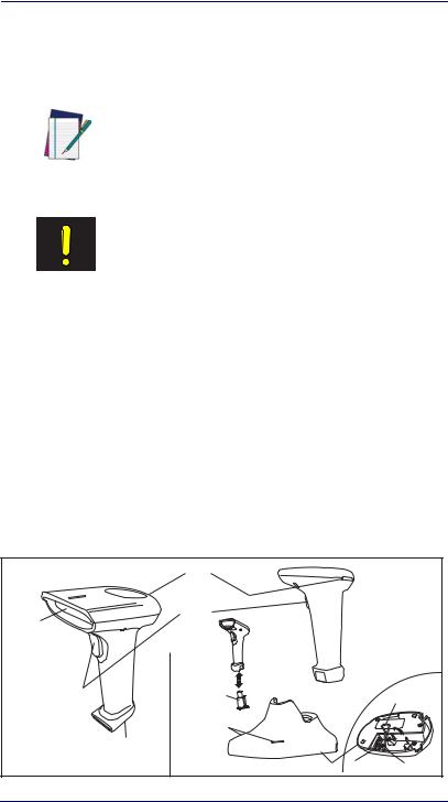
Figure 1-1a illustrates the features of the corded version of the linear imager and Figure 1-1b represents the BlueTooth version.
Figure 1-1 |
|
|
|
|
|
|
|
Indicator LEDs |
|
|
|
Scan |
|
Trigger |
|
|
|
Window |
|
|
|
|
|
|
|
Battery |
|
|
Cable |
|
|
Pack |
|
|
|
|
|
|
|
|
Retainer |
|
|
Charging LEDs |
|
|
|
a |
Interface |
b |
|
|
|
Cable Port |
|
|
|
||
|
Base Station |
Power Port |
I/F Port |
||
1-2 |
|
QuickScan® QS6500/QS6500BT |
|||

Symbologies
Symbologies
In addition to standard linear bar code symbologies, the PDF model of the linear imager also reads 2-Dimensional stacked bar code symbologies such as PDF417, Micro PDF 417 and EAN UCC Composite.
For more information plus a complete listing of available symbology types, turn to the Symbologies chapter of this manual.
Linear Imager Settings
The linear imager is factory programmed for the most common terminal and communications settings. If you need to change these settings, programming is accomplished by scanning the bar codes in this guide.
In the programming chapters, factory default settings are indicated with bold text and yellow highlighting. These defaults represent the settings for the RS-232 standard interface. For a listing of defaults for other interfaces, reference Chapter D, Default Settings, in the section titled Interface Default Exceptions.
Return to Factory Defaults
Scan the two bar codes below to reset the imager (handheld) and Base Station to factory settings. These bar codes can be used to return the imager to a “known” working state when the present programming status is not known, faulty, or suspect.
Return handheld to factory defaults
Return Base Station to factory defaults
Product Reference Guide |
1-3 |

Getting Started
NOTES
1-4 |
QuickScan® QS6500/QS6500BT |

Chapter 2
Bluetooth Models
The following features and descriptions apply only to Bluetooth (BT) models of the imager.
Linking an Imager with a Base Station
Follow these instructions to link the two devices:
1.Connect power to the Base Station. The radio LED (marked with an antenna symbol) will blink amber and the Base Station will beep.
2.To ensure the Base Station is unlinked from any other imagers, press the button located on its bottom side for three seconds.
3.Place the imager in the Base Station for one minute to get a small charge in the battery.
4.Read the label on the Base Station with the imager. The imager will sound a good read beep and the LED will flash amber.
5.Replace the imager in the Base Station to continue the charge.
Once an imager is linked to a Base Station, they will remain linked until specific action is taken to unlink them (see Unlinking). They will remain linked if the Base Station is unplugged, if the battery is removed from the imager or if the entire charge is used up, and if the imager is taken out of range of the Base Station. Under normal operation, scanning of the link label will only be required once in the life of the product.
Product Reference Guide |
2-1 |

Bluetooth Models
Unlinking
There are three ways to unlink an imager from a Base Station:
Unlink and Sleep
1.Scan the “Unlink and Sleep” bar code — Reading the unlink bar code above while the imager is in range of the Base Station will break the link between the two devices and allow another imager to link to the Base Station. It will also place the imager in Sleep Mode. If the bar code is read when the imager is out of range of its linked Base Station, the imager will unlink, but the Base Station will remain linked to the imager and will not allow another imager to be linked to it until the unlink button is pressed, the original imager is brought in range, linked, and then unlinked again.
2.Push the button on the bottom of the Base Station — Pushing the button on the Base Station while the imager is in range will break the link between the devices. If the button is pushed while the imager is out of range, the Base Station will unlink and make itself available to other imagers. The imager will not automatically break its link with the Base Station, but can be linked to any other Base Station by reading its link label .
3.Scan the link label on an alternate Base Station — Scanning the link label on a Base Station with an imager that is linked with another Base Station will drop the link between the original pair and establish a link between the imager and the new Base Station. If the new link is performed within range of the old Base Station, it is free to establish a link to the next imager that reads its link label. If it is done outside the range of the old Base Station, it retains its old link and will not allow a new imager to link to it until its unlink button is pressed.
2-2 |
QuickScan® QS6500/QS6500BT |

Battery Charging
Battery Charging
The imager contains a 1000mAh Lithium-Ion rechargeable battery. A fully charged battery will provide up to 12,000 scans over a 12 hour period. Actual charge life on the imager will depend on the configuration of the how the imager is configured via the programable features in this manual; in particular, Deep Sleep Mode and Leash Alarm settings can impact battery life.
When the imager is placed in the Base Station, the battery will automatically charge. While charging is taking place, the charging LED (marked with a battery symbol) will blink green. When the battery is fully charged, the charging LED will stay on a solid green.
If there is an error in charging either with a failure in the charging circuit or with a failure of the battery, the charging LED will flash red. When this happens, the battery should be replaced
Paging the Imager
If the imager is misplaced in the area around the Base Station, it can be located by momentarily pressing the button on the bottom of the Base Station. When the button is momentarily pressed, a message is sent to the imager instructing it to sound a series of six short beeps. If the imager is out of range of the Base Station or in Deep Sleep Mode, paging will not work.
Product Reference Guide |
2-3 |

Bluetooth Models
NOTES
2-4 |
QuickScan® QS6500/QS6500BT |
Chapter 3
General Features
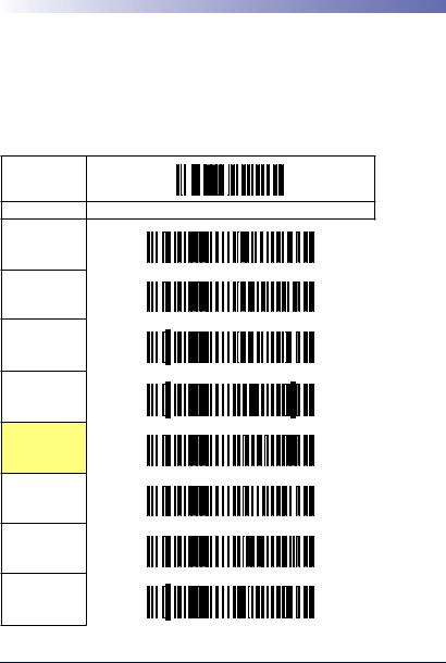
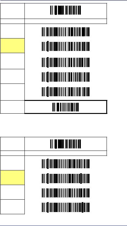
Double Read Timeout
The Double Read Timeout feature sets a time limit that determines how much time must pass before reading the same label again (e.g. two identical items in succession).
START
DURATION |
BARCODE |
0.1 Second
0.2 Second
0.3 Second
0.4 Second
0.5 Second
0.6 Second
0.7 Second
0.8 Second
Product Reference Guide |
3-1 |

General Features
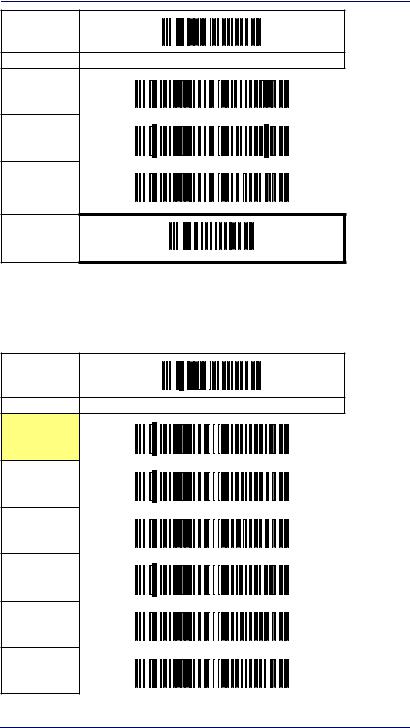
START
DURATION BARCODE
0.9 Second
1 Second
END
3-2 |
QuickScan® QS6500/QS6500BT |

Imager Timeout
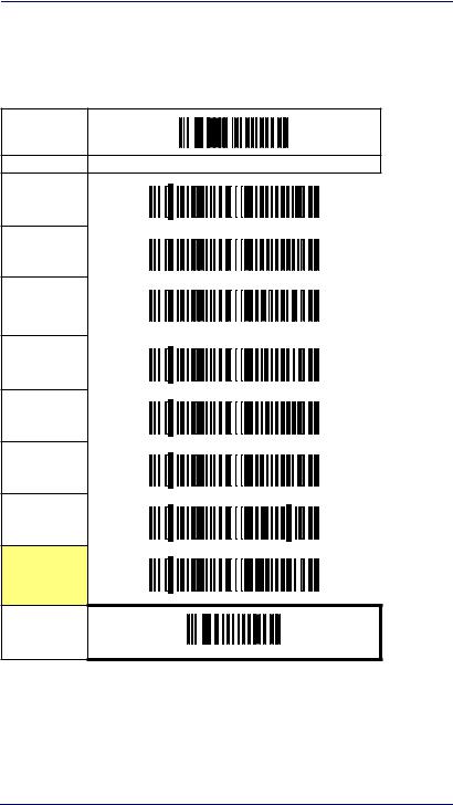
Imager Timeout
The Imager Timeout feature sets the time for automatically switching the unit off when the imager is not in use.
START
DURATION |
BARCODE |
1 Second
2 Seconds
3 Seconds
4 Seconds
5 Seconds
6 Seconds
7 Seconds
8 Seconds
9 Seconds
10 Seconds
11 Seconds
12 Seconds
Product Reference Guide |
3-3 |
General Features
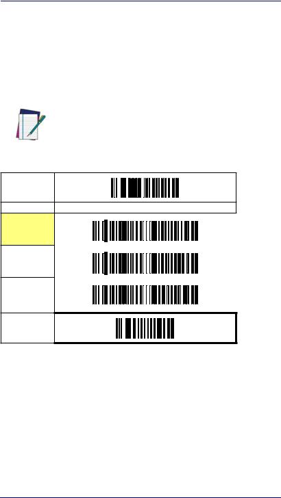
START
DURATION BARCODE
13 Seconds
14 Seconds
15 Seconds
END
Read Verification
Sets the number of times a bar code must be read before it is transmitted.
START
# of TIMES |
BARCODE |
None
1
2
3
4
5
3-4 |
QuickScan® QS6500/QS6500BT |

Read Verification
START
# of TIMES BARCODE
6
7
8
9
END
Product Reference Guide |
3-5 |

General Features
LED and Beeper Indicators
Power On Alert
Disables or enables the indication (LED and/or Beeper) that the imager is receiving power.
START
STATE |
BARCODE |
Disable
Enable
END
LED Idle State
This feature specifies the state of the green scanner LED when the scanner is idle and ready to read a label. Options are:
•Off
•On dim
START
STATE |
BARCODE |
LED OFF
LED ON
END
3-6 |
QuickScan® QS6500/QS6500BT |
LED and Beeper Indicators
Good Read: When to Indicate
This feature specifies when the imager will provide indication (beep and/ or flash its green LED) upon successfully reading a bar code. Choices are:
•Good Read = Indicate after decode
•Good Read = Indicate after transmit
•Good Read = Indicate after CTS goes inactive, then active
This option, which uses CTS, is only valid for RS-232 interfaces.
NOTE
START
INDICATE |
BARCODE |
After decode
After transmit
After CTS goes inactive, then active
END
Product Reference Guide |
3-7 |

General Features
Good Read Beep Control
This feature enables/disables the imager’s ability to beep upon a successful decode of a label.
START
STATE |
BARCODE |
Disable
Enable
END
Good Read Beep Frequency
Adjusts the good read beep to sound at a selectable low, medium or high frequency, selectable from the list below. (Controls the beeper’s pitch/ tone.)
START
FREQUENCY BARCODE
2000 Hz
2100 Hz
2200 Hz
2300 Hz
2400 Hz
3-8 |
QuickScan® QS6500/QS6500BT |
LED and Beeper Indicators
START
FREQUENCY |
BARCODE |
2500 Hz
2600 Hz
2700 Hz
2800 Hz
2900 Hz
END
Good Read Beep Length
Specifies the duration of a good read beep.
START
LENGTH |
BARCODE |
60msec
80msec
100msec
120msec
Product Reference Guide |
3-9 |

General Features
START
LENGTH BARCODE
140msec
160msec
180msec
200msec
END
3-10 |
QuickScan® QS6500/QS6500BT |
LED and Beeper Indicators
Good Read Beep Volume
Selects the beeper volume (loudness) upon a good read beep. There are five selectable volumes, with each volume increment adding approximately five decibels to the previous level.
START
VOLUME BARCODE
Off
Level 1
Level 2
Level 3
Level 4
Level 5
Level 6
Level 7
END
Product Reference Guide |
3-11 |

General Features
Scanning/Imaging Features
Scan Mode
Selects the scan operating mode for the imager. Selections are:
•Good read off — The trigger must be pressed to activate scanning. The light source stops scanning when there is a successful read or no bar code is decoded after the ”Imager Timeout” has elapsed.
•Momentary — The trigger acts as a switch. Pressing the trigger activates scanning; releasing it stops scanning.
•Alternate — The trigger acts as a toggle switch. Pressing the trigger activates scanning; pressing it a second time stops scanning
•Timeout off — The trigger must be pressed to activate scanning, The imager stops scanning if no barcode is decoded within the time duration set for the ”Imager Timeout” period.
•Stand Mode — The imager continuously reads regardless of whether the trigger is pressed or ”Imager Timeout” has elapsed.
3-12 |
QuickScan® QS6500/QS6500BT |
 Loading...