


DKC146SLDB

Model • Modèle • Modelo
v2 05.10 DM
• Owner’s Use and Care Guide
• Guide d’utilisation et d'entretien
• Manual de instrucciones
KEG COOLER
GLACIÈRE DE BIÈRE PRESSION
BARRIL REFRIGERADOR
DKC146SLDB
Danby Products Limited, Ontario, Canada N1H 6Z9
Danby Products Inc., Findlay, Ohio, USA 45840
GLACIÈRE DE BIÈRE PRESSION
Guide d'utilisation et d'entretien
• Consignes de sécurité importantes ....................
• Caractéristiques ..................................................
• Instructions d’installation ....................................
• Notice d’installation du baril à bière....................
• Utilisation ............................................................
• Soins et entretien ...............................................
• Dépannage .........................................................
• Garantie ..............................................................
Contents
3,4
5
6,7
7-11
12,13
14
14
15
BARRILREFRIGERADOR
Manual de uso y mantenimiento
• Instrucciones de seguridad importantes ............
• Caracteristicas ....................................................
• Instrucciones d'instalacion ..................................
• Instrucciones para la instalación
del barril de cerveza ...........................................
• Instrucciones de funcionamiento ........................
• Limpieza y mantenimiento ..................................
• Solucion sugeridad .............................................
• Garantia ..............................................................
CAUTION:
PRECAUTION:
ADVERTENCIA:
Read and follow all safety rules and
operating instructions before first use of this
product.
Veuillez lire attentivement les consignes de
sécurité et les instructions d’utilisation avant
l’utilisation initiale de ce produit.
Lea y observe todas las reglas de seguridad
y las instrucciones de operación antes de
usar este producto por primera vez.
Model • Modèle • Modelo DKC146SLDB
17,18
19
20,21
21-25
27
28
28
29
31,32
33
34,35
35-39
40,41
42
42
43
KEG COOLER
Owner’s Use and Care Guide
• Safety Instructions ...............................................
• Features ..............................................................
• Installation Instructions ........................................
• Beer Keg Installation Instructions .......................
• Operating Instructions .........................................
• Care and Maintenance ........................................
• Troubleshooting ...................................................
• Warranty ..............................................................
1
44
Welcome
Welcome to the Danby family. We’re proud of our quality products, and we believe in dependable service; like you will
find in this owner’s use and care guide, and like you will receive from our friendly customer service department. Best of
all, you will experience these values each and every time you use your Danby Keg Cooler. That’s important, because
your new appliance will be a part of your family for a long time.
For easy reference, may we suggest that you attach a copy of your sales receipt to this page, and note the information
below; you will need this information to obtain service under warranty.
Model No:
Serial No:
Date Purchased:
Before you call for service, there are a few things you can do to help us
serve you better.
Read this Owner’s Use and Care Guide:
It contains instructions to help you use and maintain your appliance
properly.
If you received a damaged appliance:
Immediately contact the builder (or dealer) that sold you the Beverage
Center.
Save time and money:
Check the Trouble shooting section before calling. This section helps you
solve common problems that may occur.
If you do need service, you can relax knowing help is only a phone call
away.
Need Help?
Tel: 1-800-26-
(1-800-263-2629)
2
Important Safety Information
READ AND FOLLOW ALL SAFETY INSTRUCTIONS
GROUNDING
INSTRUCTIONS
FOR YOUR SAFETY: Pertaining to the risk of Fire, Electric Shock or Injury to Persons.
• This appliance must be grounded. In the event of a malfunction or
breakdown, grounding will reduce the risk of electric shock by providing
a path of least resistance for electric current.
• This appliance is equipped with a power cord having an equipment
grounding conductor and grounding plug. The plug must be plugged into
an appropriate wall outlet that is installed and grounded in accordance
with all existing local codes and ordinances.
• Consult a qualified electrician or service person if the grounding
instructions are not clearly understood, or if doubt exist as to whether
your electrical wall outlets are properly grounded.
WARNING
If it becomes difficult to breathe and/or
your head starts to ache, abnormal concentrations of carbondioxide (CO2) may
be present in the area....
CLOSE THE MAIN VALVE ON THE
CO2 CYLINDER, VENTILATE AND
LEAVE THE ROOM IMMEDIATELY!
1. Always check the D.O.T.
(Department of Transport) as
well as the T.C. (Transport
Canada) testdate located on the
neckof the cylinder before
installation. If the date is older
than five (5) years,do not use,
return the gas cylinder to a gas
supplier for re-certification
(service charges may be
applicable).
2. Always connect a CO2 gas
cylinder to a regulator.Failure to
do so could result in an
explosion which can possibly
result in death or injury when the
cylinder valve is opened.
3. Never connect a CO2 gas
cylinder directly to beer keg.
4. Always secure a CO2 gas
cylinder in an "upright" position.
5. Always keep a CO2 gas cylinder
away from heat.
6. Never drop or throw a CO2 gas
cylinder.
7. Never connect a CO2 cylinder
unless there are two (2) safety
mechanism's in the pressure
system;
(a) One at or on the CO2 regulator.
(b) One at or on the product
container coupler in the
pressure gas line.
NOTE: The regulator andkeg
coupler supplied with this unit are
inclusive of such safety
mechanisms.
8. CO2 gas cylinders should be
stored in the coolest part of the
establishment (preferably) at
70ºF (21ºC) and must always be
securely fastened in an "upright"
position.
9. Always ventilate area after any
leakage of CO2.
WARNING CO CAN BE
DANGEROUS!
2
CO2 Cylinders when charged contain
high pressure compressed gas which can
be hazardous if not handled properly.
Read and understand the following
procedures for CO2 cylinders before
installation;
3
• This appliance must be connected to a properly grounded electrical
outlet (see Grounding Instructions)
• Do not operate this appliance if it has a damaged power cord or plug.
• Do no use this product near water, for example: in a wet basement, near
a swimming pool or sink.
• Do not defrost this appliance using other electric appliances (i.e. hair
dryer) and never attempt to scrape or remove ice/frost from the
evaporator (cold plate) with sharp objects.
• Always disconnect the appliance from the power supply before cleaning
and/or attempting repairs/servicing.
SAFETY
PRECAUTIONS
Repairs should be performed by qualified service personnel only.
IMPORTANT WARNING
• If you have purchased this appliance to replace an old one remove
either the gaskets, latches, lids or doors from the unused appliance. If it
was equipped with a door lock that cannot be opened from the inside,
(lock bolt) make sure the lock is removed, disabled or destroyed before
discarding, this will make it impossible for children to accidentally lock
themselves inside the appliance and suffocate.
• The refrigerator system of this appliance is filled with refrigerant and
insulating substances which should be treated and processed separately.
Call your nearest service agent or specialized servicing center. If you are
unable to locate one, contact your local authorities for proper disposal
instructions. Be careful not to damage any of the refrigeration lines of the
appliance.
DON’T WAIT DO THIS
NOW!
Improper disposal of worn out
appliances pose a risk of
entrapment to children.
Beer is easily available with Danby's new Keg Cooler, however, it is not
intended to be available to people under the legal age to consume beer. A
beer faucet lock kit for the purpose of limiting access, is readily available
and can be purchased through our after sales service department (see
‘Optional Accessories’ ). Danby does not assume liability for the unlawful
use or consumption of the beer.
PLEASE DRINK RESPONSIBLY AND PLEASE DON'T
DRINK AND DRIVE!
IMPORTANT
WARNING
Important Safety Information
READ AND FOLLOW ALL SAFETY INSTRUCTIONS
4
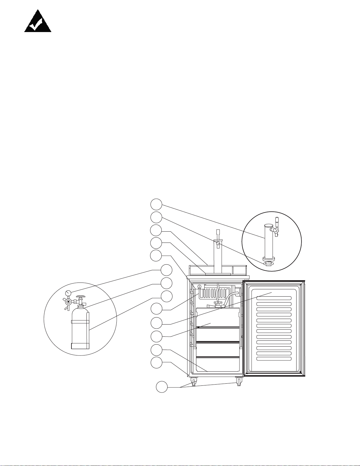
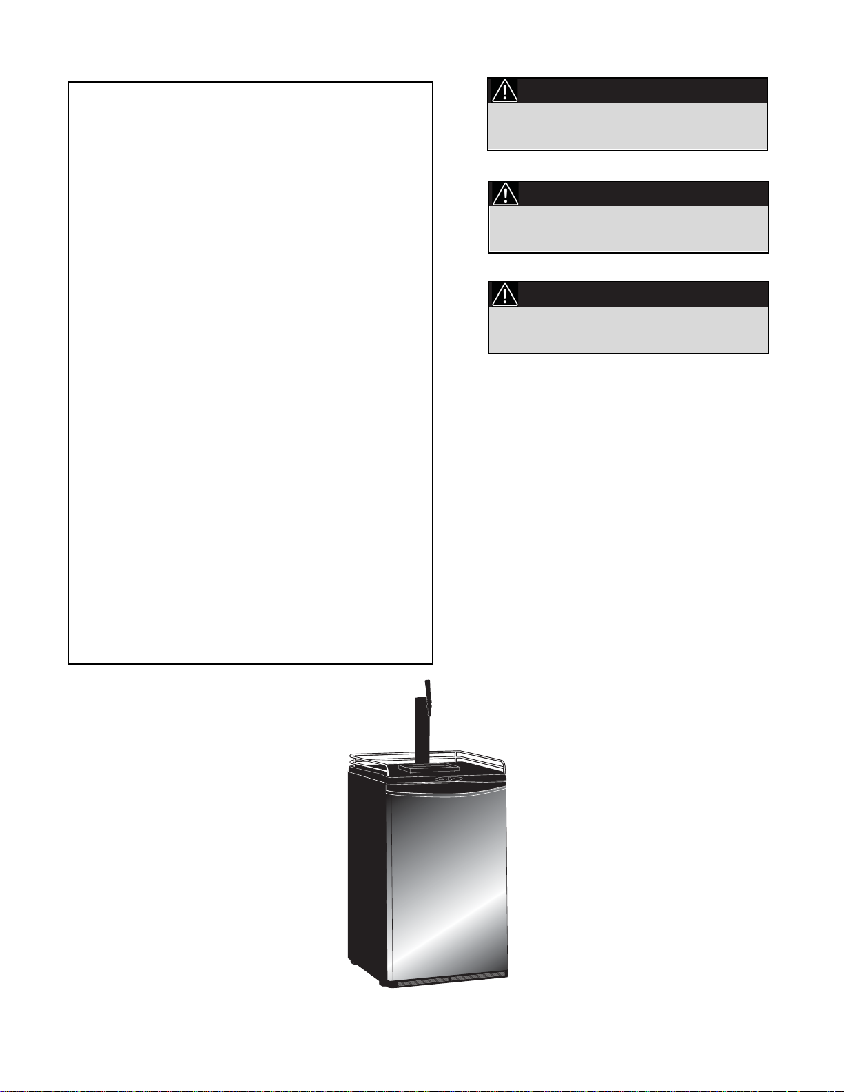
Features
CHILL N’ TAP ACCESSORIES
INCLUDED
ACCESSORIES
Remove and inspect all accessories supplied with this unit are present
and in good condition. In the event any of the accessories are missing
and /or not in good condition, please call Danby TOLL FREE at the
number listed below and speak with one of our Customer Service
Representatives. (1-800-263-2629)
BEER TOWER
1. Beer Tower
2. Plastic Gasket
3. Safety Guard Rail
4. Drip Tray
5. Adjustable Thermostat
6. CO2 Regulator
7. CO2 Gas Cylinder
8. CO2 Gas Cylinder Support
9. Evaporator
10. Reversible Door
11. Beer Keg (not included)
12. Metal Plate
13. Metal Washers(2)
14. Castors with Lock (4)
5
1
ASSEMBLY
2
3
4
BACK
5
9
10
11
12
13
14
6
7
8

Installation Instructions
BEFORE USING YOUR
BEER DISPENSER
• Remove the exterior and interior packing.
• Check to be sure you have all of the following parts:
• 1 Safety Guard Rail
• 1 Drip Tray (2 Pieces)
• 1 CO2 Cylinder Support
• 1 CO2 Regulator (Box)
• 1 CO2 Empty Cylinder(Box)
• 1 CO2 Air Line Hose (Red)
• 1 Beer Keg Coupler (Box)
• 1 Beer Tower
• 1 Pull Handle (Beer TowerFaucet)
• 1 Metal Wrench
• 4 Plugs: For Guard Rail Holes
• 1 Metal Plate For Cabinet Bottom
• 2 Steel wire shelves
• 1 Steel Clamp for Red Hose
• 4 Castors with locks
• 2 Metal Washers
• Before plugging in the keg cooler, let it stand upright for approximately 2
hours. This will reduce the possibility of a malfunction in the cooling
system from handling during transportation.
• Clean the interior surface with lukewarm water using a soft cloth.
INSTALLATION OF
BEER DISPENSER
• This appliance is designed to be free standing only, and should not be
recessed or built-in.
• Place your Beer Dispenser on a floor that is strong enough to support
the Beer Dispenser when it is fully loaded.
• Allow 3 inches of space between the back and sides of the Beer
Dispenser, which allows the proper air circulation to cool the compressor.
• Locate the Beer Dispenser away from direct sunlight and sources of heat
(stove, heater, radiator, etc.). Direct sunlight may affect the acrylic
coating and heat sources may increase electrical consumption. Extreme
cold ambient temperatures may also cause the Beer Dispenser not to
perform properly. This unit is not designed for outside installation (ie
garages, porches, etc.)
• Avoid locating the Beer Dispenser in excessive humidity.
• Plug the Beer Dispenser into a dedicated, properly installed-grounded
wall outlet. Do not under any circumstances cut or remove the third
(ground) prong from the power cord. Any questions concerning power
and or grounding should be directed toward a certified electrician or an
authorized service center.
• After plugging the appliance into a wall outlet, allow the unit to cool down
for 2-3 hours before placing any contents in the Beer Dispenser
compartment.
ELECTRICAL
CONNECTION
Improper use of the grounded plug can result in the risk of
electrical shock. If the power cord is damaged, have it replaced by
an authorized service center.
WARNING
This Beer Dispenser should be properly grounded for your safety. The
power cord of this Beer Dispenser is equipped with a three-prong plug
which mates with standard three prong wall outlets to minimize the
possibility of electrical shock.
Do not under any circumstances cut or remove the third ground prong
from the power cord supplied.
Use of extension cords is not recommended.
6
Installation Instructions
ELECTRICAL
CONNECTION (cont)
This Beer Dispenser requires a standard 115/120-volt, 60Hz electrical
outlet with three-prong ground receptacle. The cord should be secured
behind the Beer Dispenser and not left exposed or dangling to prevent
accidental injury.
Never unplug the Beer Dispenser by pulling the power cord. Always grip
the plug firmly and pull straight out from the receptacle.
CO2 GAS CAN BE DANGEROUS
CO2 cylinders contain high-pressure compressed gas which can
be hazardous if not handled properly. Make sure you READ and
UNDERSTAND the following procedures for CO2 cylinders
BEFORE INSTALLATION.
WARNING
1. ALWAYS connect the CO2 cylinder to a regulator. Failure to do so
could result in explosion with possible injury when the cylinder valve is
opened.
2. NEVER connect the CO2 cylinder directly to the product container.
3. ALWAYS follow correct procedures when cylinders are changed.
4. ALWAYS secure the cylinder in an upright position.
5. NEVER drop or throw a CO2 cylinder.
6. ALWAYS keep a CO2 cylinder away from heat. Store extra cylinders in
a cool place (preferably 70°F). Securely fasten with a chain in an
upright position when storing.
7. ALWAYS ventilate and leave the area immediately if CO2 leakage has
occurred.
8. ALWAYS check the D.O.T. test date on the cylinder neck before
installation. If over five (5) years, do not use, return cylinder to gas
supplier.
9. NEVER connect a product container unless there are two (2) safety’s in
the pressure system:
a. One at or on the CO2 regulator
b. One at or on the product coupler or in the pressure gas line.
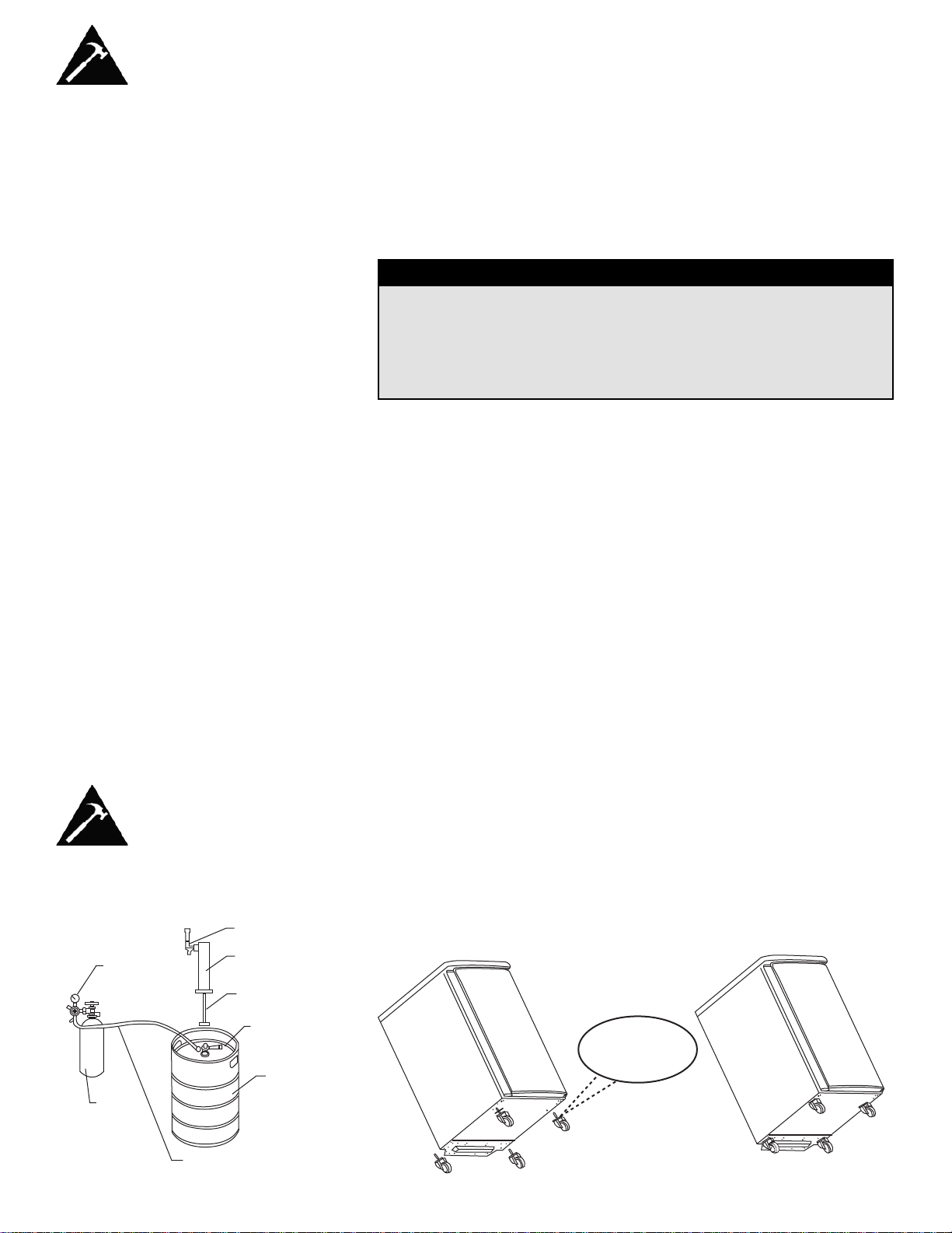
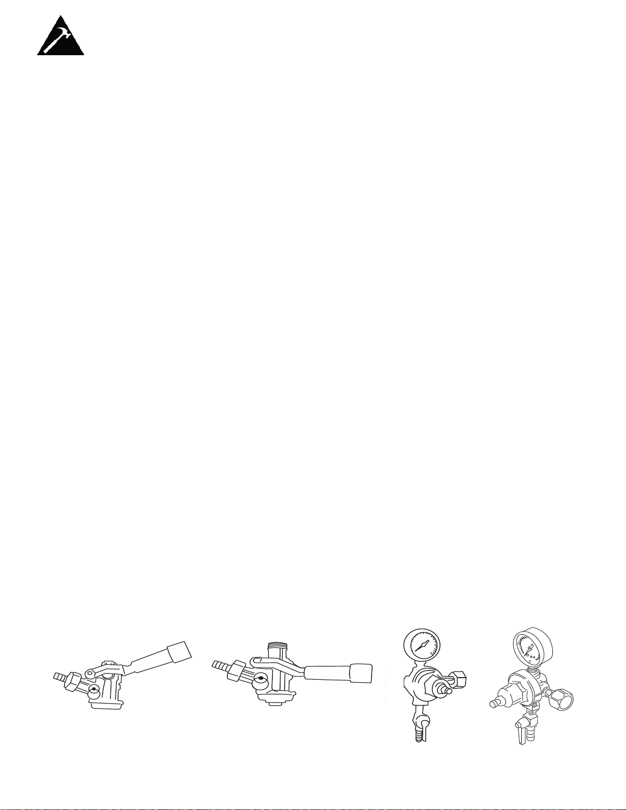
Beer Keg Installation Instructions
RED PRESSURE HOSE
LY
SINGLE GAUGE
Keg Installation Sketch
• Install the four castors with lock provided into the unit’s bottom (four
screw holes pre-supplied) The two metal gaskets are used for the front
two Castors. Figure (1) before installation. Figure (II) is the final version.
Figure 1 Figure 2
7
PRESSURE
REGULATOR
TOWER
CO2 T ANK
FAUCET ASSEMB
TOWER
CLEAR HOSE
WITH WING NUT
AMERICAN
SANKEY TAP
KEG
METAL
WASHERS
Beer Keg Installation Instructions
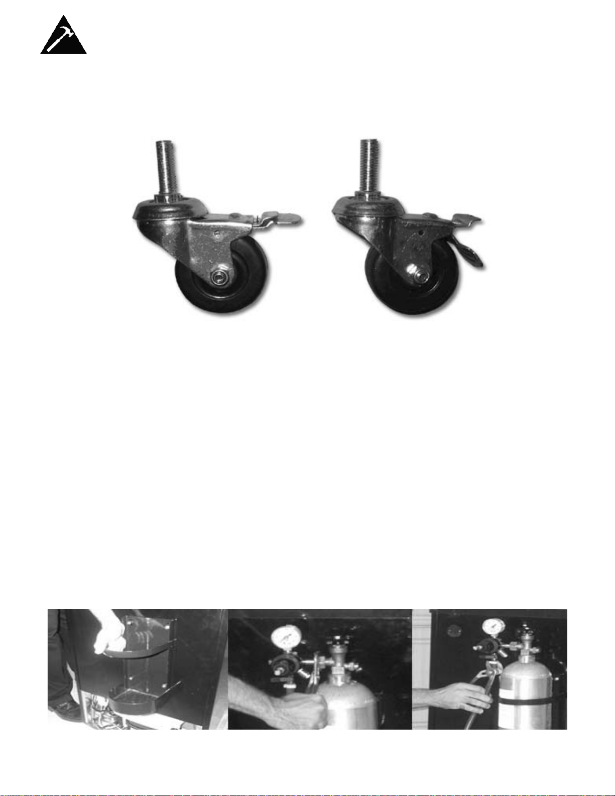
CASTOR BRAKE GUIDE
STEP ON TO BRAKE
STEP ON TO RELEASE
BRAKE
INSTALLATION OF CO2
CYLINDER SUPPORT
• Install the metal support provided onto the 4 studs located on the exterior
back wall. Align the holes in the support with the studs and push down
firmly. (See Figure 1)
Figure 1 Figure 2 Figure 3
INSTALLATION OF CO2
CYLINDER
• The CO2 Cylinder does not come filled. The cylinder must be filled with
CO2 prior to use.
• Install your fully charged cylinder into the support stand.
INSTALLATION OF CO2
REGULATOR
• Attach the CO2 regulator to the cylinder by turning the regulator nut onto
cylinder valve, making sure washer is securely inserted into connecting
nut. Tighten snug using an adjustable wrench (not supplied) and assure
there are no leaks. (See Figure 2)
INSTALLATION OF CO2
AIR LINE OUTSIDE
CABINET
• Remove plug located at the exterior back (top left hand corner).
• Save it for later use if you decide to convert unit to a refrigerator.
• Insert the open end of the air line (red) line the cabinet through the
uncovered hole. (See Figure 4)
8
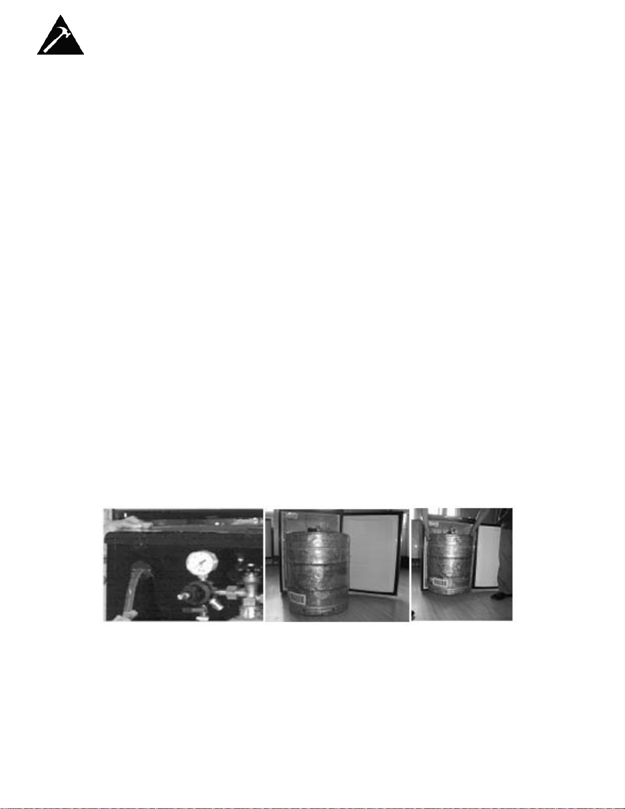
Beer Keg Installation Instructions
INSTALLATION OF CO2
AIR LINE HOSE TO
REGULATOR
• Attach the open end of the red hose to the hose barb connection on the
regulator
• Secure hose by using one clamp provided. Use pliers/screwdriver to
tighten clamp to prevent leaks. (See Figure 3)
INSTALLATION OF THE
BEER TOWER
• Remove the top plug by twisting and pulling out, saving it for later use if
you decide to convert unit to an all refrigerator unit.
• Unravel the beer line (clear hose) from the tower and insert the beer line
and wing nut through the uncovered hole on top.
• Lock the beer tower assembly to the top and make sure to position the
beer faucet so it is aligned with the cabinet front (6 o’clock position). You
accomplish this by aligning the bottom of the beer tower to the 3 grooves
on the top cabinet and tighten by hand clockwise to properly lock.
• The plastic gasket (# 2 in parts list), can be used to make the connection
between the tower and the cooler tighter if needed. If Beer Tower will not
turn to lock in place, try removing the plastic gasket.
INSTALLATION OF
PROTECTIVE METAL
PLATE
• This plate should always be installed when the keg is in place to protect
against unnecessary damage to the floor of the cabinet.
INSTALLATION OF THE
BEER KEG
• Position the beer keg directly in front of the open door. Using keg
handles only, carefully lift the beer keg. (See Figure 5)
• To place the beer keg inside the cabinet, brace your knees behind the
beer keg. Lift the front of the keg just enough so the front edge of the
keg is resting on the front edge of the Beer Dispenser bottom cabinet.
(See Figure 6)
• Grasp the keg handles and slide it all the way into the cabinet.
Figure 4
Figure 5 Figure 6
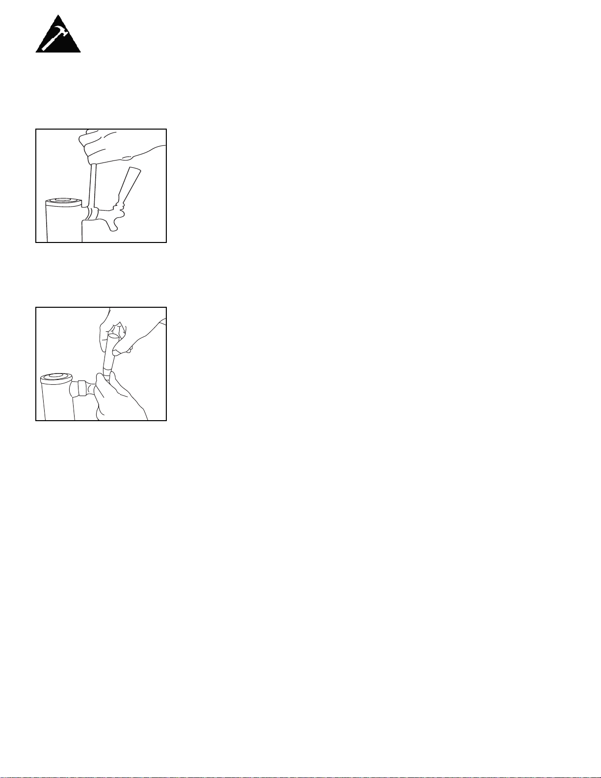
INSTALLATION OF THE
KEG COUPLER
• Insert the keg coupler provided into the locking neck of the beer keg and
turn it clockwise to lock into position, making sure the keg coupler is in
the closed position. (See Figure 7)
9
INSTALLATION OF THE
CO2 AIR LINE HOSE
• Attach the end of the air line (red) hose provided to the hose connection
on the keg coupler.
Beer Keg Installation Instructions
CONNECTING THE BEER
TOWER TO COUPLER
• Make sure the washer is properly inserted into the wing nut.
• Make sure the small round bead is in place (dropped down into the top
of the coupler).
• Make sure the ball retainer is in place on the coupler, with the ‘arms’
down into the coupler.
• Place wing nut into the top of the coupler turning until tight.
HOW TO TAP A KEG OF
BEER
• Make sure that the CO2 is turned off, and the Secondary valve on the
regulator is in the ‘Closed’ position.
• Pull out and release the pressure release valve on the Coupler to purge
any air pressure.
• Make sure the beer tower faucet is in the closed position.
• Pull tapping handle out and press downward until it locks into position.
(See Figure 8) The keg is now tapped.
OPENING THE CO2
CYLINDER MAIN VALVE
• Make sure the secondary shut-off valve (shown in figure 9 in ‘Open’
position) is closed. To open the main CO2 cylinder valve, slowly turn the
main valve counter-clockwise until fully open.
• Notice the needle on the regulator gauge start to climb.
ADJUSTING THE CO2
REGULATOR
The gauge monitors low internal keg pressure and should be adjusted to
read between 10-12 psi. (See Figure 10). The pressure can be adjusted
as needed.
• Release adjustment lock nut marked 2.
• Using a flat screwdriver, turn regulator screw marked 3.
o To increase pressure, turn screw clockwise.
o To decrease pressure, turn screw counter - clockwise.
• Retighten lock nut marked 2.
• Open secondary shut off valve to let CO2 flow into the keg.
• Allow several minutes for the keg to properly pressurize. Regulator
gauge may drop while this happens. (Note: Listen for hissing along all
connections to identify if there are any leaks)
Figure 7
Figure 8
Figure 9 Figure 10
10
Beer Keg Installation Instructions
SPANNER FAUCET
WRENCH
Spanner faucet wrench is provided for either removing or tightening
connection.
PLASTIC FAUCET
LEVER
Attach the black plastic lever (pull handle) to the top of the faucet by
tightening it by hand clockwise until the end, holding in the silver nut
underneath so it does not turn. If there is still a small drip from the faucet,
you may have tightened the plastic lever too much and may need to
unscrew silver snug counter-clockwise (as shown) one turn.
DISPENSING OF BEER
• Keep beer keg refrigerated at all times.
• Never allow beer lines to dry out.
• Use clean beer glassware before pouring.
• Hold glass at a 45° angle when 2/3 full, start to straighten glass as the
glass fills.
• Always make sure the faucet handle is pushed all the way back.
Note: Keg sizes that can be used in your beer dispenser
1/2 barrel 59 Liters 15.5 gals 1984 oz. 164/12-oz. Glass
1/4 barrel 30 Liters 7.8 gals. 992 oz. 82/12-oz. Glass
1/6 barrel 20 Liters 5.2 gals. 661 oz. 55/ 12-oz. Glass
1/8 barrel 15 Liters 4.0 gals. 496 oz. 41/ 12-oz. Glass
Note: Our Beer dispenser accepts standard kegs up to 16-1/8” in
diameter, and up to 23-3/8” in height. Check with your distributor to make
sure keg is correct size.
11

Operating Instructions
12
AUTOMATIC
DEFROSTING
CONVERTING TO AN
“ALL REFRIGERATOR”
There is no need to defrost the Beer Dispenser. Defrost water collects and
passes thru the drain outlet in the rear wall into a tray located above the
compressor, where it evaporates.
NOTE: If the unit is unplugged, power lost, or turned off; you must wait 3
to 5 minutes before restarting the unit. If you attempt to restart before this
time delay, the Beer Dispenser may not start.
1. Turn off the control knob to the “OFF” position.
2. Close the main valve on the CO2 cylinder.
3. Close the secondary shut-off valve on the regulator pipe.
4. Close the connection between the beer keg and the keg coupler.
5. Drain any remaining beer from the lines.
6. Disconnect the beer line and CO2 air line from the keg coupler
7. Remove the beer keg.
8. Remove the keg coupler.
9. Disconnect the air line from the CO2 cylinder.
10. Remove the CO2 air line from cabinet plug
11. Replace the air line rear cabinet plug
12. Remove the beer tower. Also pull the beer line thru the top of the
cabinet
13. Replace the top cabinet plug
14. Adjust temperature as desired.
Operating Instructions
CHANGING THE
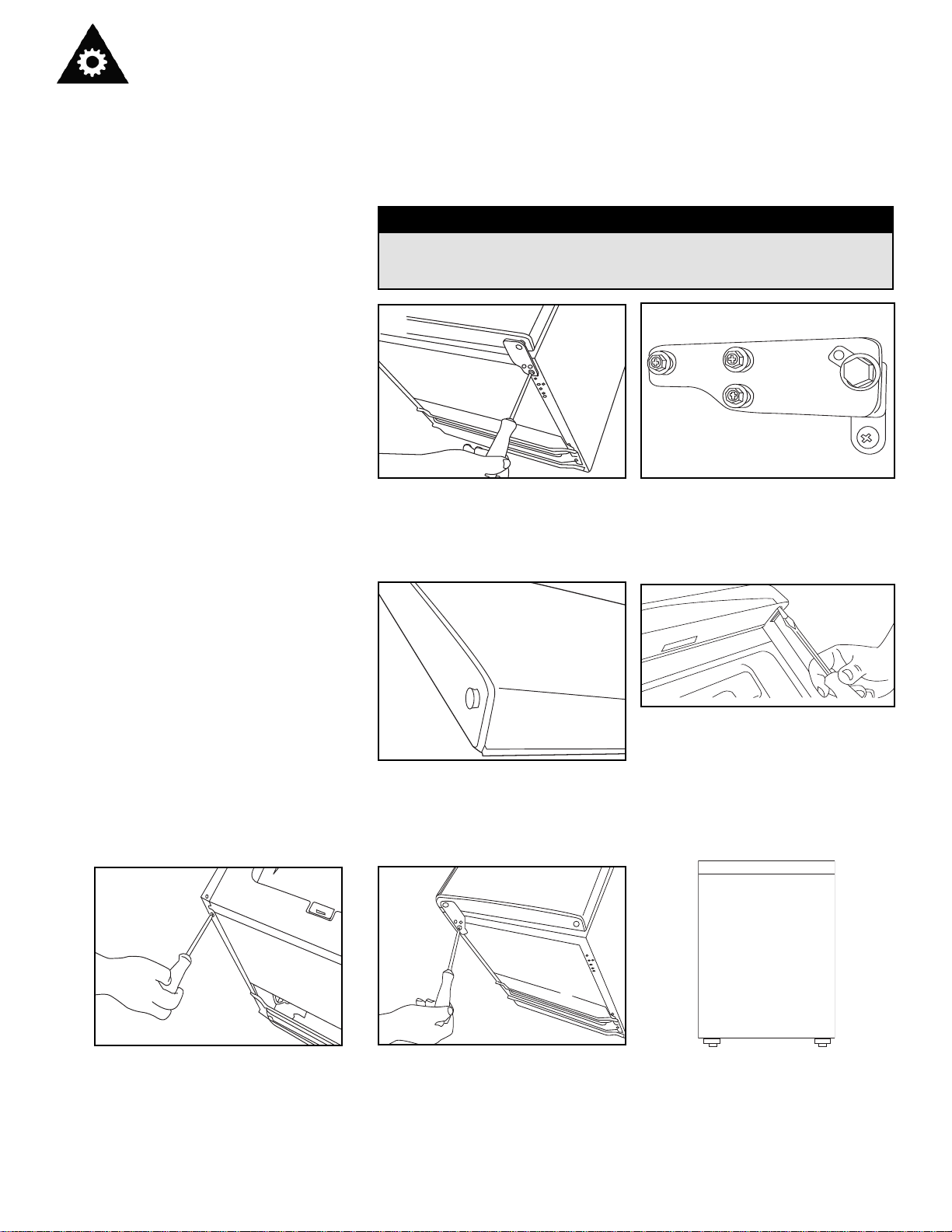
REVERSIBLE DOOR
This Beer Dispenser has a door that can be set to open from the left or
right side. The unit is delivered to you with the door opening from the left
side. To reverse the opening direction, please follow the instructions
below.
To avoid personal injury to yourself and/or property, we
ecommend that someone assist you during the door reversal
process.
CAUTION
Undo the three screws in each
bracket using the Phillips
screwdriver.
Remove the screws and bracket.
Place to one side.
Slide the Larder Fridge door down
about 15cm (6’’) and off the top
hinge pin and lift away from the
freezer.
Using the flat bladed screw driver
remove the pin from the top bracket.
Replace it in the hinge bracket on
the opposite side.
Remove the screw from the side of
the Larder Fridge where the
bracket is to be re-fitted.
Slide the Larder Fridge door back
on to the top hinge, making sure it’s
the right way up. Screw the bottom
hinge into place on the new side.
Check that the door is aligned
horizontally and vertically and
that the seals are closed on all
sides before finally tightening
the bottom hinge. Re-adjust
the leveling feet.
1
2
3
4
5
6
7
13
 Loading...