


 Loading...
D-Link™ DGS-3100 SERIES
GIGABIT STACKABLE MANAGED SWITCH
User Manual
V2.20

Information in this document is subject to change without notice. © 2007 D-Link Computer Corporation. All rights reserved.
Reproduction in any manner whatsoever without the written permission of D-Link Computer Corporation is strictly forbidden.
Trademarks used in this text: D-Link and the D-Link logo are trademarks of D-Link Computer Corporation; Microsoft and Windows are registered trademarks of Microsoft Corporation.
Other trademarks and trade names may be used in this document to refer to either the entities claiming the marks and names or their products. D-Link Computer Corporation disclaims any proprietary interest in trademarks and trade names other than its own.
FCC Warning
This equipment has been tested and found to comply with the limits for a Class A digital device, pursuant to Part 15 of the FCC Rules. These limits are designed to provide reasonable protection against harmful interference when the equipment is operated in a commercial environment. This equipment generates, uses, and can radiate radio frequency energy and, if not installed and used in accordance with this user’s guide, may cause harmful interference to radio communications. Operation of this equipment in a residential area is likely to cause harmful interference in which case the user will be required to correct the interference at his own expense.
CE Mark Warning
This is a Class A product. In a domestic environment, this product may cause radio interference in which case the user may be required to take adequate measures.
Warnung!
Dies ist ein Produkt der Klasse A. Im Wohnbereich kann dieses Produkt Funkstoerungen verursachen. In diesem Fall kann vom Benutzer verlangt werden, angemessene Massnahmen zu ergreifen.
Precaución!
Este es un producto de Clase A. En un entorno doméstico, puede causar interferencias de radio, en cuyo case, puede requerirse al usuario para que adopte las medidas adecuadas.
Attention!
Ceci est un produit de classe A. Dans un environnement domestique, ce produit pourrait causer des interférences radio, auquel cas l`utilisateur devrait prendre les mesures adéquates.
Attenzione!
Il presente prodotto appartiene alla classe A. Se utilizzato in ambiente domestico il prodotto può causare interferenze radio, nel cui caso è possibile che l`utente debba assumere provvedimenti adeguati.
VCCI Warning
May, 2008 P/N

|
Table of Contents |
PREFACE.................................................................................................................................................................. |
I |
System Overview .................................................................................................................................................................. |
ii |
Viewing the Device............................................................................................................................................................... |
ii |
DGS-3100 Series Front Panel ........................................................................................................................................... |
ii |
DGS-3100-24TG Front Panel ........................................................................................................................................... |
ii |
Device Management Methods.............................................................................................................................................. |
iii |
User Guide Overview........................................................................................................................................................... |
iv |
Intended Audience ............................................................................................................................................................... |
iv |
Notes, Notices, and Cautions ............................................................................................................................................... |
iv |
Safety Cautions .................................................................................................................................................................... |
iv |
General Precautions for Rack-Mountable Products ............................................................................................................. |
vi |
GETTING STARTED................................................................................................................................................ |
1 |
Using the Web-Based User Interface .................................................................................................................................... |
1 |
Understanding the D-Link Embedded Web Interface ........................................................................................................... |
1 |
Using the Tool Menu ............................................................................................................................................................ |
3 |
Displaying the Stack Status............................................................................................................................................... |
3 |
Locating Devices............................................................................................................................................................... |
3 |
Backing up and Restoring Configuration Files ................................................................................................................. |
4 |
Resetting the Device ......................................................................................................................................................... |
5 |
Downloading the Firmware............................................................................................................................................... |
6 |
Rebooting the System ....................................................................................................................................................... |
8 |
Using the Web System Components..................................................................................................................................... |
9 |
CONFIGURING BASIC CONFIGURATION .......................................................................................................... |
10 |
Viewing Device Information............................................................................................................................................... |
11 |
Defining System Information.............................................................................................................................................. |
13 |
Defining IP Addresses ........................................................................................................................................................ |
14 |
Managing Stacking ............................................................................................................................................................. |
15 |
Managing Stacking Modes.............................................................................................................................................. |
15 |
Advanced Stacking.......................................................................................................................................................... |
15 |
Stack Startup Process ...................................................................................................................................................... |
17 |
Building Stacks – Quick Start ......................................................................................................................................... |
19 |
Stack Management Examples ......................................................................................................................................... |
20 |
Configuring Stacking ...................................................................................................................................................... |
26 |
Defining Ports ..................................................................................................................................................................... |
27 |
Configuring Port Properties ............................................................................................................................................ |
27 |
Viewing Port Properties .................................................................................................................................................. |
29 |
ARP Settings....................................................................................................................................................................... |
30 |
Configuring User Accounts................................................................................................................................................. |
31 |
Managing System Logs....................................................................................................................................................... |
33 |
Configuring SNTP .............................................................................................................................................................. |
34 |
Configuring Daylight Savings Time ............................................................................................................................... |
36 |
Configuring SNMP ............................................................................................................................................................. |
40 |
Defining SNMP Views ................................................................................................................................................... |
41 |
Defining SNMP Groups.................................................................................................................................................. |
42 |
Defining SNMP Users..................................................................................................................................................... |
44 |
Defining SNMP Communities ........................................................................................................................................ |
46 |
Defining SNMP Host Table ............................................................................................................................................ |
47 |
Defining SNMP Engine ID ............................................................................................................................................. |
49 |
Enabling SNMP Traps .................................................................................................................................................... |
50 |
DHCP Auto Configuration.................................................................................................................................................. |
51 |
Dual Image Services ........................................................................................................................................................... |
52 |
Firmware Information ..................................................................................................................................................... |
52 |
Config Firmware Image .................................................................................................................................................. |
53 |
CONFIGURING L2 FEATURES............................................................................................................................. |
54 |
Enabling Jumbo Frames...................................................................................................................................................... |
55 |
Configuring VLANs ........................................................................................................................................................... |
56 |
Understanding IEEE 802.1p Priority .............................................................................................................................. |
56 |
VLAN Description.......................................................................................................................................................... |
56 |
Notes about VLANs on the DGS-3100 Series ................................................................................................................ |
56 |
IEEE 802.1Q VLANs...................................................................................................................................................... |
56 |
802.1Q VLAN Tags........................................................................................................................................................ |
58 |
Port VLAN ID................................................................................................................................................................. |
59 |
Tagging and Untagging................................................................................................................................................... |
59 |
Ingress Filtering .............................................................................................................................................................. |
59 |
Default VLANs ............................................................................................................................................................... |
60 |
VLAN and Trunk Groups ............................................................................................................................................... |
60 |
VLAN Status................................................................................................................................................................... |
60 |
Defining VLAN Properties ............................................................................................................................................. |
61 |
Configuring GVRP ............................................................................................................................................................. |
63 |
Defining Trunking............................................................................................................................................................... |
65 |
Traffic Segmentation........................................................................................................................................................... |
67 |
Configuring LACP.............................................................................................................................................................. |
68 |
Defining IGMP Snooping ................................................................................................................................................... |
69 |
Configuring Port Mirroring................................................................................................................................................. |
72 |
Configuring Spanning Tree................................................................................................................................................. |
74 |
Defining Spanning Tree Global Parameters.................................................................................................................... |
75 |
Defining STP Port Settings ............................................................................................................................................. |
77 |
Defining Multiple Spanning Tree Configuration Identification...................................................................................... |
79 |
Defining MSTP Port Information ................................................................................................................................... |
80 |
Defining Forwarding and Filtering ..................................................................................................................................... |
82 |
Defining Unicast Forwarding.......................................................................................................................................... |
82 |
Defining Multicast Forwarding....................................................................................................................................... |
83 |
CONFIGURING QUALITY OF SERVICE .............................................................................................................. |
85 |
Understanding QoS ............................................................................................................................................................. |
87 |
Defining Bandwidth Settings .............................................................................................................................................. |
88 |
Configuring Storm Control ................................................................................................................................................. |
89 |
Mapping Ports to Packet Priorities...................................................................................................................................... |
90 |
Mapping Priority to Classes (Queues) ................................................................................................................................ |
91 |
Configuring QoS Scheduling Mechanism........................................................................................................................... |
92 |
Defining Multi-Layer CoS Settings .................................................................................................................................... |
93 |
SECURITY FEATURES ......................................................................................................................................... |
94 |
Configuring Safeguard Engine............................................................................................................................................ |
95 |
Configuring Trust Host ....................................................................................................................................................... |
96 |
Configuring Port Security ................................................................................................................................................... |
97 |
Configuring Guest VLANs ................................................................................................................................................. |
98 |
Configuring Port Authentication 802.1X ............................................................................................................................ |
99 |
Configuring MAC Authentication (by using Guest VLAN, 802.1X and Radius pages) .............................................. |
104 |
Defining RADIUS Settings........................................................................................................................................... |
107 |
Configuring Secure Socket Layer Security ....................................................................................................................... |
108 |
Configuring Secure Shell Security.................................................................................................................................... |
110 |
Defining SSH Algorithm Settings................................................................................................................................. |
111 |
Defining Application Authentication Settings .................................................................................................................. |
113 |
Configuring Authentication Server Hosts ..................................................................................................................... |
114 |
Defining Login Methods ............................................................................................................................................... |
115 |
Defining Enable Methods ............................................................................................................................................. |
117 |
Configuring Local Enable Password............................................................................................................................. |
119 |
MONITORING THE DEVICE............................................................................................................................... |
120 |
Viewing Stacking Information.......................................................................................................................................... |
121 |
Viewing CPU Utilization .................................................................................................................................................. |
122 |
Viewing Port Utilization ................................................................................................................................................... |
123 |
Viewing Packet Size Information ..................................................................................................................................... |
124 |
Viewing Received Packet Statistics .............................................................................................................................. |
125 |
Viewing UMB_cast Packet Statistics............................................................................................................................ |
126 |
Viewing Transmitted Packet Statistics.......................................................................................................................... |
127 |
Viewing RADIUS Authenticated Session Statistics ......................................................................................................... |
129 |
Viewing ARP Table .......................................................................................................................................................... |
130 |
Viewing Router Ports........................................................................................................................................................ |
131 |
Viewing Session Table...................................................................................................................................................... |
132 |
Viewing IGMP Group Information................................................................................................................................... |
133 |
Defining Dynamic and Static MAC Addresses................................................................................................................. |
134 |
Viewing System Log......................................................................................................................................................... |
136 |
MANAGING POWER OVER ETHERNET DEVICES.......................................................................................... |
137 |
Defining PoE System Information .................................................................................................................................... |
138 |
Displaying and Editing PoE System Information ............................................................................................................. |
140 |
DEFINING ACCESS PROFILE LISTS................................................................................................................ |
141 |
ACL Configuration Wizard............................................................................................................................................... |
142 |
Defining Access Profile Lists............................................................................................................................................ |
144 |
Defining Access Rules Lists ............................................................................................................................................. |
157 |
Finding ACL Rules ........................................................................................................................................................... |
160 |
TECHNICAL SUPPORT...................................................................................................................................... |
171 |
DGS-3100 Series Gigabit Stackable Managed Switch User Manual
Preface
This preface provides an overview to the guide, and includes the following sections:
•System Overview
•Viewing the Device
•Device Management Methods
•User Guide Overview
•Intended Audience
•Notes, Notices, and Cautions
•Safety Cautions
•General Precautions for Rack-Mountable Products
i
DGS-3100 Series Gigabit Stackable Managed Switch User Manual
System Overview
The DGS-3100 series and the DGS-3100-24TG Gigabit Ethernet Switches enhance networks by providing a powerful switch that eliminates network bottlenecks, enabling network administrators to fine tune network configurations.
The DGS-3100 series and the DGS-3100-24TG are perfect for departmental and enterprise connections, and are ideal for backbone and server connections.
Viewing the Device
The devices described in this section are stackable Gigabit Ethernet Managed Switches. Device management is performed using an Embedded Web Server (EWS) or through a Command Line Interface (CLI). The device configuration is performed via an RS-232 interface. This section contains descriptions for the following:
•DGS-3100 series Front Panel
•DGS-3100-24TG Front Panel
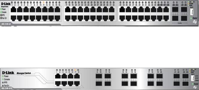
DGS-3100 Series Front Panel
The DGS-3100 series provides 24/48 high performance 1000BASE-T ports. The 1000Base-T ports operate at 10/100/1000, and connect to backbones, end-stations, and servers. The DGS-3100 series also provides 4 Mini-GBIC (SFP) combo ports which connect fiber optic media to switches, servers, or network backbone. The DGS-3100 series provides an additional RS-232 port (console port) for managing the switch via a console terminal or PC with a Terminal Emulation Program.
Figure 1 DGS-3100 Series 48 Port Front Panel
DGS-3100 Series Front Panel
The DGS-3100-24TG provides eight high performance 1000BASE-TX ports. The ports operate at 10/100/1000, and connect to backbones, end-stations, and servers. The DGS-3100-24TG also provides 16 Mini-GBIC (SFP) ports which connect fiber optic media to switches, servers, or network backbone. The DGS-3100-24TG provides an additional RS-232 port (console port) for managing the switch via a console terminal or PC with a Terminal Emulation Program.
Figure 2 DGS-3100-24TG Front Panel
ii
DGS-3100 Series Gigabit Stackable Managed Switch User Manual
Device Management Methods
The DGS-3100 series and DGS-3100-24TG provide different methods for managing the device including:
•Web Based Management Interface
•SNMP-Based Management
•Command Line Console
Web Based Management Interface
Once the device is installed, network mangers can configure the switch, monitor the LED panel, and display statistics graphically via a web browser, including:
•Netscape Navigator (version 7.0 and higher)
•Microsoft® Internet Explorer (version 5.0).
•Mozilla Firefox (version 2.0)
SNMP-Based Management
The system also supports SNMPv1, SNMPv2c, and SNMPv3. The SNMP agent decodes the incoming SNMP messages, and replies to requests with MIB objects stored in the database. The SNMP agent updates the MIB objects to generate statistics and counters.
Command Line Console
The device also supports device configuration using the Command Line Interface. A terminal is connected to device via the serial console port.
iii

DGS-3100 Series Gigabit Stackable Managed Switch User Manual
User Guide Overview
This section provides an overview to the DGS-3100 series and the DGS-3100-24TG Switch Manual, including the guide structure and a chapter overview:
•Section 1, Getting Started — Provides general background for understanding and using the Embedded Web System, including an explanation of the interface buttons and general system functions.
•Section 2, Defining the Basic Device Configuration — Provides information for viewing system information, defining IP addresses, managing stacking, defining ports, configuring SNMP management, and defining the system time settings.
•Section 3, Configuring L2 Features — Provides information for enabling and configuring Jumbo frames, VLANs, Trunks (LAGs), Traffic Segmentation, Multicast forwarding, and Spanning Tree.
•Section 4, Configuring Quality of Service — Provides information for ability to implement QoS and priority queuing within a network.
•Section 5, Security Features — Provides information for enabling and configuring device security.
•Section 6, Monitoring the Device — Provides information for monitoring the device.
•Section 7, Managing Power over Ethernet Devices — Provides information configuring the PoE function.
•Section 8, Defining Access Profile Lists — Provides information for configuring the ACL.
User Guide Overview
The DGS-3100 series/DGS-3100-24TG User Guide contains information for configuring and managing the DGS-3100 series/DGS-3100-24TG Switches. This guide is intended for network managers familiar with network management concepts and terminology.
Notes, Notices, and Cautions
NOTE: A NOTE indicates important information that helps you make better use of your device.
NOTICE: A NOTICE indicates either potential damage to hardware or loss of data and tells you how to avoid the problem.
CAUTION: A CAUTION indicates a potential for property damage, personal injury, or death.
Safety Cautions
Use the following safety guidelines to ensure your own personal safety and to help protect your system from potential damage. Throughout this safety section, the caution icon ( ) is used to indicate cautions and precautions that you need to review and follow.
To reduce the risk of bodily injury, electrical shock, fire, and damage to the equipment, observe the following precautions.
iv
DGS-3100 Series Gigabit Stackable Managed Switch User Manual
•Do not service any product except as explained in your system documentation. Opening or removing covers that are marked with the triangular symbol with a lightning bolt may expose you to electrical shock. Only a trained service technician should service components inside these compartments.
•If any of the following conditions occur, unplug the product from the electrical outlet and replace the part or contact your trained service provider:
–The power cable, extension cable, or plug is damaged.
–An object has fallen into the product.
–The product has been exposed to water.
–The product has been dropped or damaged.
–The product does not operate correctly when you follow the operating instructions.
•Keep your system away from radiators and heat sources. Also, do not block the cooling vents.
•Do not spill food or liquids on your system components, and never operate the product in a wet environment. If the system gets wet, see the appropriate section in your troubleshooting guide or contact your trained service provider.
•Do not push any objects into the openings of your system. Doing so can cause a fire or an electric shock by shorting out interior components.
•Use the product only with approved equipment.
•Allow the product to cool before removing covers or touching internal components.
•Operate the product only from the type of external power source indicated on the electrical ratings label. If you are not sure of the type of power source required, consult your service provider or local power company.
•To help avoid damaging your system, be sure the voltage selection Switch (if provided) on the power supply is set to match the power available at your location:
–115 volts (V)/60 hertz (Hz) in most of North and South America and some Far Eastern countries such as South Korea and Taiwan
–100 V/50 Hz in eastern Japan and 100 V/60 Hz in western Japan
–230 V/50 Hz in most of Europe, the Middle East, and the Far East
•Also be sure that attached devices are electrically rated to operate with the power available in your location.
•Use only approved power cable(s). If you have not been provided with a power cable for your system or for any AC-powered option intended for your system, purchase a power cable that is approved for use in your country. The power cable must be rated for the product and for the voltage and current marked on the product's electrical ratings label. The voltage and current rating of the cable should be greater than the ratings marked on the product.
•To help prevent an electric shock, plug the system and peripheral power cables into properly grounded electrical outlets. These cables are equipped with three-prong plugs to help ensure proper grounding. Do not use adapter plugs or remove the grounding prong from a cable. If you must use an extension cable, use a 3-wire cable with properly grounded plugs.
•Observe extension cable and power strip ratings. Make sure that the total ampere rating of all products plugged into the extension cable or power strip does not exceed 80 percent of the ampere ratings limit for the extension cable or power strip.
•To help protect your system from sudden, transient increases and decreases in electrical power, use a surge suppressor, line conditioner, or uninterruptible power supply (UPS).
•Position system cables and power cables carefully; route cables so that they cannot be stepped on or tripped over. Be sure that nothing rests on any cables.
•Do not modify power cables or plugs. Consult a licensed electrician or your power company for site modifications. Always follow your local/national wiring rules.
•When connecting or disconnecting power to hot-pluggable power supplies, if offered with your system, observe the following guidelines:
–Install the power supply before connecting the power cable to the power supply.
–Unplug the power cable before removing the power supply.
–If the system has multiple sources of power, disconnect power from the system by unplugging all power cables from the power supplies.
v
DGS-3100 Series Gigabit Stackable Managed Switch User Manual
Move products with care; ensure that all casters and/or stabilizers are firmly connected to the system. Avoid sudden stops and uneven surfaces.
General Precautions for Rack-Mountable Products
Observe the following precautions for rack stability and safety. Also refer to the rack installation documentation accompanying the system and the rack for specific caution statements and procedures.
Systems are considered to be components in a rack. Thus, "component" refers to any system as well as to various peripherals or supporting hardware.
CAUTION: Installing systems in a rack without the front and side stabilizers installed could cause the rack to tip over, potentially resulting in bodily injury under certain circumstances. Therefore, always install the stabilizers before installing components in the rack.
After installing system/components in a rack, never pull more than one component out of the rack on its slide assemblies at one time. The weight of more than one extended component could cause the rack to tip over and may result in serious injury.
•Before working on the rack, make sure that the stabilizers are secured to the rack, extended to the floor, and that the full weight of the rack rests on the floor. Install front and side stabilizers on a single rack or front stabilizers for joined multiple racks before working on the rack.
Always load the rack from the bottom up, and load the heaviest item in the rack first. Make sure that the rack is level and stable before extending a component from the rack.
Use caution when pressing the component rail release latches and sliding a component into or out of a rack; the slide rails can pinch your fingers.
After a component is inserted into the rack, carefully extend the rail into a locking position, and then slide the component into the rack.
Do not overload the AC supply branch circuit that provides power to the rack. The total rack load should not exceed 80 percent of the branch circuit rating.
Ensure that proper airflow is provided to components in the rack.
Do not step on or stand on any component when servicing other components in a rack.
NOTE: A qualified electrician must perform all connections to DC power and to safety grounds. All electrical wiring must comply with applicable local or national codes and practices.
CAUTION: Never defeat the ground conductor or operate the equipment in the absence of a suitably installed ground conductor. Contact the appropriate electrical inspection authority or an electrician if you are uncertain that suitable grounding is available.
CAUTION: The system chassis must be positively grounded to the rack cabinet frame. Do not attempt to connect power to the system until grounding cables are connected. Completed power and safety ground wiring must be inspected by a qualified electrical inspector. An energy hazard will exist if the safety ground cable is omitted or disconnected.
vi

DGS-3100 Series Gigabit Stackable Managed Switch User Manual
Protecting Against Electrostatic Discharge
Static electricity can harm delicate components inside your system. To prevent static damage, discharge static electricity from your body before you touch any of the electronic components, such as the microprocessor. You can do so by periodically touching an unpainted metal surface on the chassis.
You can also take the following steps to prevent damage from electrostatic discharge (ESD):
1.When unpacking a static-sensitive component from its shipping carton, do not remove the component from the antistatic packing material until you are ready to install the component in your system. Just before unwrapping the antistatic packaging, be sure to discharge static electricity from your body.
2.When transporting a sensitive component, first place it in an antistatic container or packaging.
3.Handle all sensitive components in a static-safe area. If possible, use antistatic floor pads and workbench pads and an antistatic grounding strap.
Battery Handling Reminder
CAUTION: This is danger of explosion if the battery is incorrectly replaced. Replace only with the same or equivalent type recommended by the manufacturer. Discard used batteries according to the manufacturer's instructions.
vii

DGS-3100 Series Gigabit Stackable Managed Switch User Manual
1
GETTING STARTED
To begin managing the device, simply run the browser installed on the management station and point it to the IP address defined for the device. For example; http://123.123.123.123. Please note that the proxy for session connection should be turned off.
NOTE: The Factory default IP address for the Switch is 10.90.90.90.
This section contains information on starting the D-Link Embedded Web Interface. To access the D-Link user interface:
1.Open an Internet browser. Ensure that pop-up blockers are disabled. If pop-up blockers are enabled, edit, add, and device information messages may not open.
2.Enter the device IP address in the address bar and press Enter.
Using the Web-Based User Interface
The user interface provides access to various switch configuration and management windows, allows you to view performance statistics, and permits you to graphically monitor the system status. The screen captures in this Guide represent the DGS-3100-48 48 port device. The Web pages in the 24 port and the DGS-3100-24TG devices may vary slightly.
Understanding the D-Link Embedded Web Interface
The D-Link Embedded Web Interface Device Information Page contains the following information:
View |
Description |
Tree View |
Displays the different system features, and configuration options. |
|
|
Zoom View |
Located at the top of the home page, the port LED indicators provide a visual |
|
representation of the ports on the D-Link front panel. |
|
|
Menu Information View |
Located below the Zoom View, displays Save, Tool menu, Stack ID, and Logout buttons. Also |
|
displays Up Time information and User Loggin Identification. |
Device Information View |
Located in the main part of the home page, the device view provides a view of the |
|
device, an information or table area, and configuration instructions. |
|
|
Stacking Status View |
Located at the bottom left corner of the home page, the stacking status view provides |
|
a graphic representation of the stacking links and ports status. |
|
|
|
Table 1-1. Web Interface Views |
1
DGS-3100 Series Gigabit Stackable Managed Switch User Manual
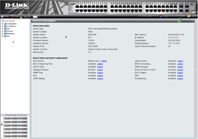
|
Figure 1-1. Device Information Page |
The following table describes the main 6 areas on the Device Information Page: |
|
|
|
View |
Description |
1. Tree View |
Select the folder or window to be displayed. The folder icons can be opened to display the |
|
hyperlinked menu buttons and subfolders contained within them. |
|
|
2. Device |
Presents Switch information based on the selection and the entry of configuration data |
Information View |
|
|
|
3. Menu |
Presents the Save button, a menu for accessing device tools, and a menu for Stack ID |
Information View |
selection. The current Up Time and current User Loggin information is reported. The Logout button is |
|
also here. |
|
|
4. Zoom View |
Presents a graphical near real-time image of the front panel of the Switch. This area displays |
|
the Switch's ports and expansion modules, showing port activity, duplex mode, or flow |
|
control, depending on the specified mode. |
|
Various areas of the graphic can be selected for performing management functions, including |
|
port configuration |
|
|
5 Device |
Provides access to the device logout, and provides information about the Safe Guard mode |
Application Buttons |
currently enabled on the device. |
|
|
6 Stacking Status |
Provides a graphic representation of the stacking links and ports status. |
View |
|
|
|
|
Table 1-2. Main Areas |
2
DGS-3100 Series Gigabit Stackable Managed Switch User Manual
Using the Tool Menu
The tool menu contains menu options for:
•Displaying the Stack Status
•Locating Devices
•Backing up and Restoring Configuration Files
•Resetting the Device
•Downloading the Firmware
•Rebooting the System
Displaying the Stack Status
The Stacking Information Page provides specific information for stacked devices. For more information regarding the stacking setup, see Managing Stacking section.
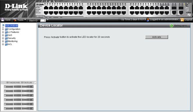
Locating Devices
The Device Locator Page enables locating system devices by activating LED locators. To locate devices:
1.Click  > Device Locator. The Device Locator Page opens.
Figure 1-2. Device Locator Page
2.Click  . The LED locator is activated for 20 seconds On which the letter “L” will flash on the master unit.
3
DGS-3100 Series Gigabit Stackable Managed Switch User Manual
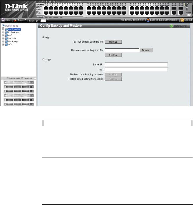
Backing up and Restoring Configuration Files
The Config Backup and Restore Page contains fields for downloading and uploading the configuration file from the device through HTTP or TFTP server. To back up and restore configuration files:
1.Click  > Config Backup & Restore. The Config Backup and Restore Page opens.
|
|
Figure 1-3 Config Backup and Restore Page |
The Config Backup and Restore Page contains the following fields: |
||
|
|
|
Field |
|
Description |
Http |
|
Indicates that the system files are backed up or restored via an HTTP server. The possible |
|
|
field values are: |
|
|
Backup current setting to file — Backs up the current configuration files via the HTTP |
|
|
server. |
|
|
Restore saved setting from file — Restores the current configuration files via the HTTP |
|
|
server. |
|
|
|
TFTP |
|
Indicates that the system files are backed up or restored via an TFTP server. The possible field |
|
|
values are: |
|
|
Server IP — Specifies the TFTP Server IP Address to which files are backed up or from |
|
|
which they are restored. |
|
|
File — Indicates the file that is backed up or restored. |
|
|
Backup current setting to server — Backs up the current configuration files via the TFTP |
|
|
server. |
|
|
Restore saved setting from server — Restores the current configuration files via the TFTP |
|
|
server. |
|
|
|
2.Select HTTP or TFTP field.
3.Define the selected server method fields.
To backup files, click  .
.
To restore files, click  .
.
4
DGS-3100 Series Gigabit Stackable Managed Switch User Manual
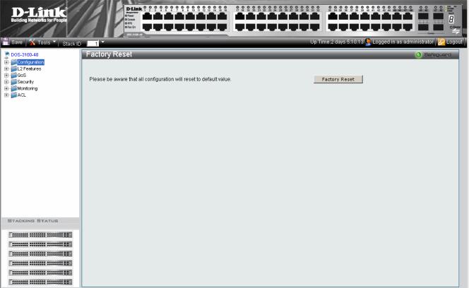
Resetting the Device
The Factory Reset Page restores the factory defaults. To restore the device to the factory default settings:
1.Click  > Reset. The Factory Reset Page opens:
Figure 1-4 Factory Reset Page
2.Click  . The factory default settings are restored once it completely reloaded, and the device is updated.
5
DGS-3100 Series Gigabit Stackable Managed Switch User Manual
Downloading the Firmware
The ‘Firmware Download’ web page is used to download the firmware files that will be used to manage the device.
NOTE: Firmware version 1.x.x supports 4 SKUs od DGS-3100 series: DGS-3100-24, DGS-3100- 24P, DGS-3100-48 and DGS-3100-48P, Firmware version 2.x.x supports in addition the 5th SKU: DGS-3100-24TG.
Firmware version 2.x.x includes as well additional features comparing to version 1.x.x, for more details, please refer to the Release Notes.
When upgrading firmware from version 1.x.x to version 2.x.x on the switch, the user should upgrade the boot software as well from version 1.0.0.3 to version 1.0.0.4
Upgrade Procedure – Important Notes:
ACL backward compatibility issue - In firmware 1.x.x, TCP/UDP ports of access profile are in hexadecimal instead of decimal values. In version 2.x.x, TCP/UDP port value entries are in decimal value. However - if the user upgrades the switch firmware from version 1.x.x to version 2.x.x, the value will be retained as hexadecimal value.
ACLs access rules priority did not work in firmware version 1.x.x. In firmware version 2.x.x, the priority is supported and it is not allowed two identical access rules priority from different access profiles. If the user download configuration file from version 1.x.x which including ACLs which has more than one rule, it might not work and there will be an error message. The user can delete and create the ACLs again if he encountered a problem.
Tacacs/Radius backwards compatibility issue - In firmware version 1.x.x, it is possible to configure up to 4 Tacacs /Radius servers. In firmware version 2.x.x, it is possible to configure up to 3 servers from each type. In addition to that it was not required to configure priority to Tacacs servers in 1.x.x while in 2.x.x it is required. If the user configured 4 servers in version 1.x.x and try to download the configuration to firmware 2.x.x, he will get an error message, the same event will happened because of the Tacacs priority.
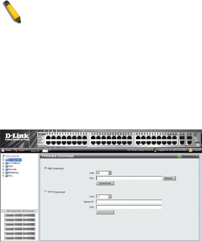
The Firmware Download Page enables downloading files either via an HTTP or a TFTP server. To download Firmware:
1.Click  > Firmware Download. The Firmware Download Page opens:
Figure 1-5 Firmware Download Page
6

DGS-3100 Series Gigabit Stackable Managed Switch User Manual
The Firmware Download Page contains the following fields:
Field
HTTP Download
TFTP Download
Description
Indicates that the Firmware file is downloaded via an HTTP server.
Unit — Indicates if the Firmware file is downloaded to a specific stacking member or to All stacking members.
File — Indicates the Firmware file that is downloaded to the stack or specific device.
Indicates that the Firmware file is downloaded via a TFTP server.
Unit — Indicates if the Firmware file is downloaded to a specific stacking member or to All stacking members.
Server IP Address — Specifies the TFTP Server IP Address from which files are downloaded.
File — Indicates the Firmware file that is downloaded to the stack or specific device.
2.Select HTTP or TFTP Download field.
3.Define the Unit field.
4.For Http download, define the File field, or alternatively, browse to select the file.
5.Click  . The Firmware is downloaded, and the device is updated.
7
DGS-3100 Series Gigabit Stackable Managed Switch User Manual
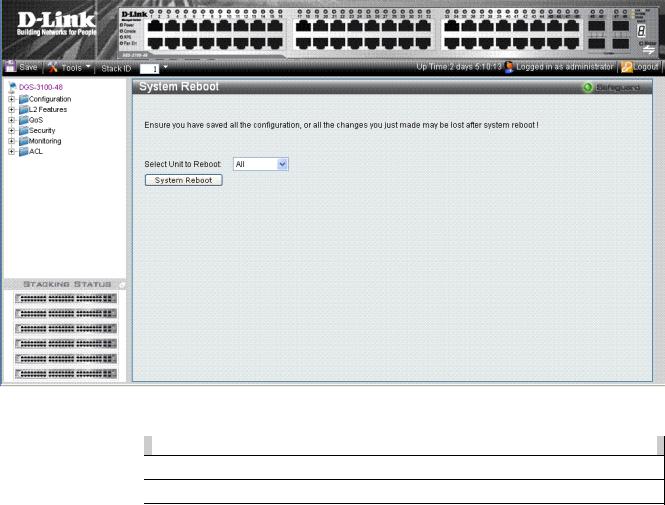
Rebooting the System
The System Reboot Page provides a method for selecting one, or all of the units to be rebooted. To reboot the system:
1.Click  > System Reboot. The System Reboot Page opens:
Figure 1-6 System Reboot Page
The System Reboot Page contains the Select Unit to Reboot field. The possible values are:
Value |
|
Description |
All |
|
Reboots all stacking members. |
|
|
|
01 - 06 |
|
Reboots the specific stack member. |
|
|
|
2.Define the Select Unit to Reboot field.
3.Click  . The selected unit(s) is/are rebooted.
8
DGS-3100 Series Gigabit Stackable Managed Switch User Manual
Using the Web System Components
The following table contains information regarding the list of buttons:
Component |
Name |
Description |
|
Activate |
Activates field commands |
|
|
|
|
Add |
Adds selected items |
|
|
|
|
ALL |
Selects all |
|
|
|
|
Apply |
Applies field settings |
|
|
|
|
Backup |
Evokes backup |
|
|
|
|
Cancel |
Cancels settings |
|
|
|
|
Clear |
Clears selected settings and fields |
|
|
|
|
Clear All |
Clears all settings and fields |
|
|
|
|
Delete |
Deletes selected fields |
|
|
|
|
Delete VID |
Deletes VLAN Identification |
|
|
|
|
Download |
Starts downloading system files. |
|
|
|
|
Edit |
Modifies configuration Information |
|
|
|
|
Factory Reset |
Resets the factory defaults |
|
|
|
|
Find |
Finds a table entry. |
|
|
|
|
System Reboot |
Reboot the system |
|
|
|
|
Refresh |
Refreshes device information. |
|
|
|
|
Restore |
Restores the specific configuration file. |
|
|
|
|
View All Entry |
Displays table entries. |
|
|
|
Table 1-3. User Interface Buttons
9

DGS-3100 Series Gigabit Stackable Managed Switch User Manual
2
CONFIGURING BASIC CONFIGURATION
This section contains information for viewing device information, defining IP addresses, managing stacking, defining port parameters, configuring system user accounts, configuring and managing system logs, defining the system time, and configuring SNMP system management. This section contains the following topics:
•Viewing Device Information
•Defining System Information
•Defining IP Addresses
•Managing Stacking
•Defining Ports
•ARP Settings
•Configuring User Accounts
•Managing System Logs
•Configuring SNTP
•Configuring SNMP
•DHCP Auto Configuration
•Dual Image Services
10

DGS-3100 Series Gigabit Stackable Managed Switch User Manual
Viewing Device Information
The Device Information Page contains parameters for configuring general device information, including the system name, location, and contact, the system MAC Address, System Up Time, and MAC addresses, and both software, boot, and hardware versions.
In addition the Device Information Page provides shortcuts to device feature pages. To define the general system information:
•Click DGS-3100-xx in the Tree View. The Device Information Page opens:
Figure 2-1 Device Information Page
The Device Information Page contains the following fields:
Field
Device Type
System Contact
System Name
System Location
Firmware Version
Hardware Version
System Time
System Up Time
Description
Displays the factory defined device name and type.
Displays the name of the contact person. The field range is 0-31 characters.
Displays the user-defined system name. The field range is 0-31 characters.
Displays the location where the system is currently running. The field range is 0-31 characters.
Displays the installed software version number.
Displays the installed device hardware version number.
Displays the system time. The field format is Day/Month/Year.
Displays the amount of time since the most recent device reboot. The system time is displayed in the following format: Days, Hours, Minutes, and Seconds. For example, 41 days, 2 hours, 22 minutes and 15 seconds.
11

|
DGS-3100 Series Gigabit Stackable Managed Switch User Manual |
|
|
Field |
Description |
Boot Version |
Displays the installed device boot version number. |
|
|
MAC Address |
Displays the MAC address assigned to the device. |
|
|
IP Address |
Displays the IP address assigned to the device. |
|
|
Subnet Mask |
Displays the subnet mask assigned to the device. |
|
|
Default Gateway |
Displays the device default gateway assigned to the device. |
|
|
Login Timeout (minutes) |
Indicates the amount of time after which if no user activity occurs, the device times out. |
|
The default is 10 minutes. |
|
|
Time Source |
Provides a shortcut to viewing the system clock settings. |
|
|
802.1D Spanning Tree |
Indicates if STP is enabled on the device, and provides a shortcut to viewing the STP |
|
settings. |
|
|
DHCP Client |
Indicates if DCHP Client is enabled on the device, and provides a shortcut to viewing the |
|
DHCP Client settings. |
|
|
Safeguard Engine |
Indicates if the Safeguard Engine is enabled on the device, and provides a shortcut to |
|
viewing the Safeguard Engine settings. |
|
|
SNMP Trap |
Indicates if SNMP Traps are enabled on the device, and provides a shortcut to viewing |
|
the SNMP Traps settings. |
|
|
SSL |
Indicates if Secure Socket Layer (SSL) is enabled on the device, and provides a shortcut |
|
to viewing the SSL settings. |
|
|
GVRP Setting |
Indicates if Group VLAN Registration Protocol is enabled. |
|
|
Jumbo Frames |
Indicates if Jumbo Frames are enabled on the device, and provides a shortcut to viewing |
|
the Jumbo Frames settings. |
|
|
BPDU Forwarding |
Indicates if BPDU Forwarding is enabled on the device, and provides a shortcut to |
|
viewing the BPDU Forwarding settings. |
|
|
IGMP Snooping |
Indicates if IGMP Snooping is enabled on the device, and provides a shortcut to viewing |
|
the IGMP Snooping settings. |
|
|
Broadcast Storm Control |
Indicates if Broadcast Storm Control is enabled on the device, and provides a shortcut to |
|
viewing the Broadcast Storm Control settings. |
|
|
802.1X Status |
Indicates if 802.1X is enabled on the device, and provides a shortcut to viewing the |
|
802.1X settings. |
|
|
SSH |
Indicates if Secure Shell Protocol (SSH) is enabled on the device, and provides a shortcut |
|
to viewing the SSH settings. |
|
|
Port Mirroring |
Indicates if Port Mirroring is enabled. |
|
|
To view settings for a device feature:
1.Select a device feature under the Device Status and Quick Configuration Section.
2.Click setting next to the feature name. The configuration page for the selected device feature opens.
12
DGS-3100 Series Gigabit Stackable Managed Switch User Manual
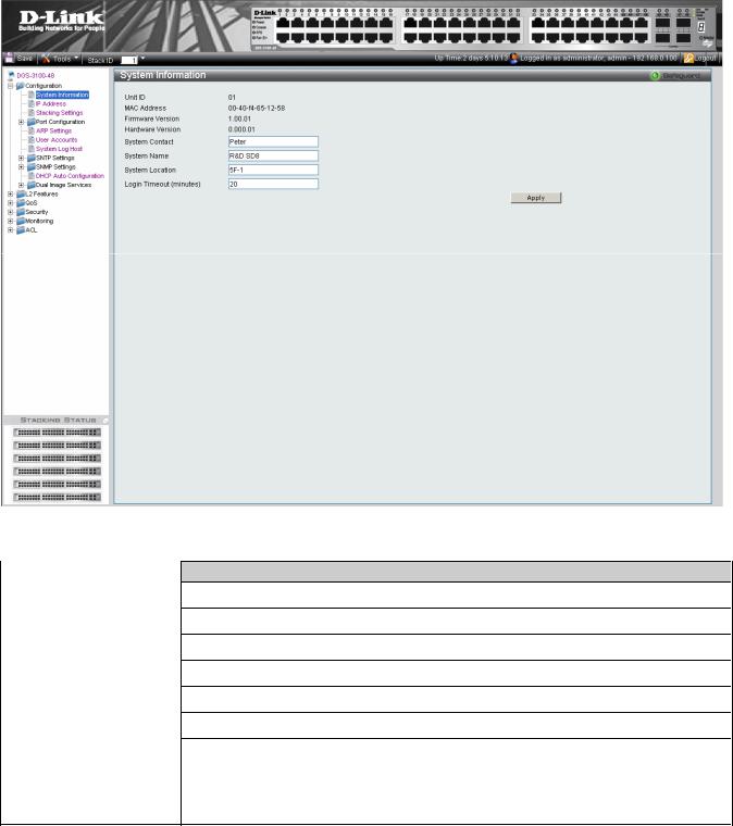
Defining System Information
The System Information Page provides device information about specific stacking members. To view system information:
1.Click Configuration > System Information. The System Information Page opens:
|
Figure 2-2 System Information Page |
The System Information Page contains the following fields: |
|
Field |
Description |
Unit ID |
Displays the stack unit ID. |
|
|
MAC Address |
Displays the MAC address assigned to the device |
|
|
Firmware Version |
Displays the stacking member’s software version number. |
|
|
Hardware Version |
Displays the stacking member’s hardware version number. |
|
|
System Contact |
Defines the name of the contact person. The field range is 0-160 characters. |
|
|
System Name |
Defines the user-defined system name. |
|
|
System Location |
Defines the location where the system is currently running. The field range is 0-160 |
|
characters. |
|
|
Login Timeout (minutes) |
Defines the amount of time the device times out when no user activity occurs. The default is |
10minutes.
2.Define the System Name field.
3.Define the System Location and Login Timeout (minutes) fields.
4.Click  . The system information is defined, and the device is updated.
13
DGS-3100 Series Gigabit Stackable Managed Switch User Manual
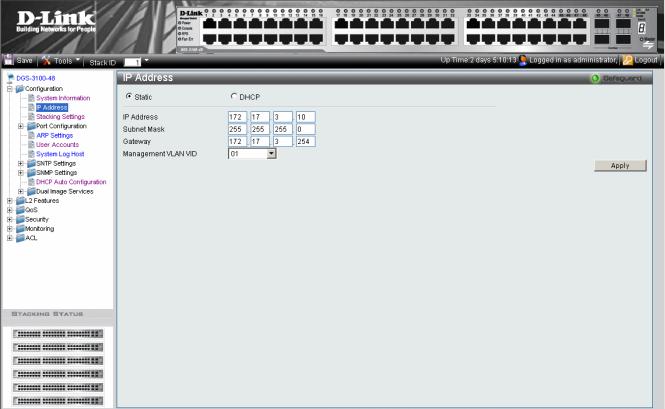
Defining IP Addresses
The IP Address Page contains fields for assigning IP addresses. Packets are forwarded to the default IP when frames are sent to a remote network via the Default Gateway. The configured IP address must belong to the same IP address subnet of one of the IP interfaces. The Dynamic Host Configuration Protocol (DHCP) assigns dynamic IP addresses to devices on a network. DHCP ensures that network devices can have a different IP address every time the device connects to the network.
1.Click Configuration > IP Address. The IP Address Page opens:
|
Figure 2-3 IP Address Page |
The IP Address Page contains the following fields: |
|
|
|
Field |
Description |
Static |
When selected, the IP address is static and user-defined in the IP Address field. This is the |
|
default value. |
|
|
DHCP |
When selected, the IP address is retrieved from a DHCP server. |
|
|
IP Address |
Defines the IP address. This field is active if the IP address is static. |
|
|
Subnet Mask |
Defines the address mask that manages sub-netting on the network. The default value is |
|
255.0.0.0. |
|
|
Gateway |
Defines the default gateway. The default gateway manages connections to other subnets |
|
and other networks. |
|
|
Management VLAN VID |
Defines the management VLAN’s VID. |
|
|
2.Select the IP address type in either the Static or DHCP fields.
3.If Static is the defined IP address type, define the IP Address field.
4.Define the Subnet Mask, Gateway, and Management VLAN VID fields.
5.Click  . The IP address information is defined, and the device is updated.
14

DGS-3100 Series Gigabit Stackable Managed Switch User Manual
Managing Stacking
Stacking enhances network flexibility by building virtual switches with more ports then are available in a single device. Stacks are managed by stacking member which called Stack Master., All other stacking members serve as ports only.
The following paragraphs provide a stacking explanation for DGS-3100 series and include the following topics:
•Managing Stacking Modes
•Advanced Stacking
•Building Stacks – Quick Start
•Stack Management Examples
•Configuring Stacking
Managing Stacking Modes
A switch may operates in one of the following modes:
•Stand-Alone- Switches operating in stand-alone mode run as an independent unit. All ports of a stand-alone switch operate as normal Ethernet links except the HX ports which are Disabled.
NOTE: The DGS-3100 series family stacking connections have two HX ports.
•Stacking - Switches operating in Stack mode run as organized group member of switches known as a Stack. A stack consists of one Stack Master, a Backup Master, and up to four Stack Member Switches. However, in specific scenarios, a single unit can be considered a Stack of One. A Stack of One is a single unit which does not connected to any other stacking members.
Either stacking or stand-alone modes can be selected by the user before the next software boot which using CLI or the Embedded WEB Interface, the new mode takes effect after the unit is rebooted. If the unit is reset to the factory defaults, the unit is reloaded in stacking Auto-Numbering mode.
Advanced Stacking
This section provides information for understanding advanced stacking concepts, including:
•Unit ID and how they are allocated
•Stacking member start up process. This section contains the following topics:
•Allocating Unit IDs
•Assigning Unit IDs
Allocating Unit IDs
Switches are shipped from the factory without a Unit ID and in Auto Assign mode. All switches must be assigned a Unit ID before switches can operate as stacking members. More than one stacking member cannot receive the same Unit ID. Unit IDs are assigned by:
•Assigned by the system administrator. Unit IDs that are assigned by the system administrator and can only be changed manually by the system administrator.
•If the system administrator does not set the Unit IDs manually, the Auto Assign initializes the switches when they are powered up. From the switches who are automatically assigned a Unit ID, one of the stacking members is assigned the Unit ID 1. That stacking member is the Stack Master. If there were more than one switch in the stack, there is a Master Election and Backup Master Election process. Following the Master Election process, the other stacking members are assigned a Unit ID by the stack Master. For more information on the Master Election process, please see Electing a Stacking Master.
15

DGS-3100 Series Gigabit Stackable Managed Switch User Manual
Stacking members maintain the assigned Unit ID even after the stacking member is rebooted. The Stack Master may reallocate IDs during system initialization to resolve duplicate ID conflicts. Manually assigned IDs cannot be changed by the Stack Master, even if there is a conflict.
Unit ID assignments or modifications are effective only during system initialization, and do not occur during the system uptime.
Stacking members do not have to be numbered in sequence, and can be interconnected, as long as each stacking has a unique ID, and at least, one stacking member serves as the Stack Master.
Assigning Unit IDs
Each stacking member has an assigned unique Unit ID. Unit ID numbers are assigned as follows:
•Unit ID 1 - Assigned to the Stack Master. The Stack Master is indicated by the Master LED on front which is lit solid green.
•Unit ID 2 - Assigned to the Backup Master
•Unit ID 3, 4, 5, and 6 - Assigned to Stacking members.
NOTE: There are cases in which a unit to which Unit ID 1 is assigned is not the stack Master but a Backup Master.
This section contains the following topics:
•Defining a Stacking Master
•Defining a Stacking Back Up Master
•Defining Stacking Members
•Master Enabled Stacking Members
•Electing a Stacking Master
Defining a Stacking Master
The stacking member assigned the Unit ID1 operates as the Stack Master.
The Stack Master provides a single point of control, configuration, and management for the entire stack. In addition, the Stack Master stores all stack member configuration. The individual stacking members do not store any configuration information.
Defining a Stacking Back Up Master
The stacking member assigned the Unit ID 2 is defined as the stack’s Backup Master.
In addition to being a stack member, Backup Master serves as a backup in case the Stack Master fails or disconnected. If the Stack Master fails or disconnected, the Backup Master takes over as the Stack Master.
The Stack Master stores an active configuration which copied on the Backup Master. The active configuration copy is used if the Backup Master takes over for the Stack Master. Only the configuration file is copied. Any dynamically filled tables, for example, learnt address, are not copied from the Stack Master to the Backup Master. If the Backup Master takes over the role of Stack Master, the Backup Master builds new dynamic tables.
Defining Stacking Members
Switches assigned the Unit IDs 3,4,5,6 are called stacking members. The Stack Master (or Backup Master if the Stack Master fails) manages the stack members operation. Stacking members cannot be directly managed or configured. If neither the Stack Master nor the Backup Master were operating, the stacking members cannot function.
Master Enabled Stacking Members
Only Stacking members assigned to Unit ID 1 or 2 are called Master Enabled stacking members. Only the Master Enabled stacking members participate in the Master Election process, and therefore can become master or backup master (that means the s with assigned IDs of 3, 4, 5 and 6 can never become neither a master nor a backup master unless their ID is changed by the system administrator or reset to the factory default firstly).
16
DGS-3100 Series Gigabit Stackable Managed Switch User Manual
Electing a Stacking Master
Whenever a stacking member (or more than one) comes up, one of the stacking members is elected to be the stack Master. The Stack Master is selected as follows:
•If one of the master enabled stacking members in the stack was set to Force Master by the system administrator (through the GUI – Stacking Master selector), that master enabled stacking member is the Stack Master. Stacking members which are defined as Force Master stacking members are manually selected as the Stack Master. Only a master enabled stacking member can be selected as the Force Master.
•If the stack contains more than one stacking member whose Unit ID is either 1 or 2, then one of the stacking members are elected the Stack Master. It does not matter if the Unit ID was originally automatically or manually assigned. These stacking members are called Master Enabled. If there is only one stacking member, that stacking member is selected as the Stack Master, even if the stacking member’s Unit ID is 2.
•If there are more than one stacking members, the two stacking members decide which stacking member is elected Stack Master by checking:
–Which stacking member has been running for a longer time. The up-time is measured in increments of 10 minutes. The stacking member running the longest is elected the Stack Master.
–If they have been running for the same amount of time, the stacking member with the Unit ID 1 is the stack Master.
–If both stacking members have been running for the same amount of time, and both stacking membes have the same Unit ID, the stacking members with the lowest MAC addressis selected as the Stack Master. The other unit is rebooted and is assigned the Unit ID 2.
–If the stack contains one or more stacking members set to the factory default states, and there is no Unit ID assigned to a stacking member, then the Stack Master is one of these stacking members. The stacking member selected to be the Master is the stacking member running for the longest time. If all stacking members are running the same amount of time, the stacking member with the lowest MAC address is selected as the Stack Master.
The Master Election results in an elected Stack Master. The Stack master has a Unit ID of 1 and the Backup Master has a Unit ID of 2 (if a Backup Master was included in the stack).
If a Master Enabled stacking member, a Unit ID of 1 or 2, is added to a stack and powered on, the newly added switch invokes Master Election process. The Master Election process occurs even though the stack has an elected master. However, the newly added switch loses in the election process (lower up-time) and joins the stack as a stacking member or Backup Master.
Stack Startup Process
When a stacking member is initialized, either powered up or rebooted, the stacking member goes through the same exact process including:
•Discovering the Stacking Master.
•Allocating Unit IDs/Resolving Unit ID Conflicts
•Unit and Stacking Port Configuration
Discovering the Stacking Master
When a stacking member is initialized in stack mode, the stacking member’s behavior depends on its Unit ID.
•If the stacking member does not have a current Unit ID the stacking member operates in Factory Default mode. If there is a Stacking Master, the stacking member is assigned a Unit ID through Unit ID Allocation. The stacking members receive a Unit ID from the Stacking Master. If the stack does not have a Stacking master then the switch participates in Master-Election, and may be elected either the new Stacking Master or Backup Master.
•If the stacking member’s current Unit ID is 1 or 2, the stacking member participates in the Master Election. For example, the Unit ID was previously allocated, or the stacking member was in a different stack.
•If the stacking member has a current Unit ID the stacking members attempts to use the Unit ID in the new stack. If the stacking member current ID is 3, 4, 5, or 6, then the stacking members attempts to connect to the running Stack Master. The new stacking member does not proceed to the next stage until there is contact with the Stack Master.
17
DGS-3100 Series Gigabit Stackable Managed Switch User Manual
These stacking members do not participate in the Master Election process, and if no Stack Master is present, the stacking members’ network ports are shut down. Only the stacking ports are operational.
Both the Stack Master and all other stacking members carry out a continuous process of Master Discovery by frequently exchanging stack control messages. This allows the stacking members to discover when a stacking member fails or is unreachable.
Allocating Unit IDs/Resolving Unit ID Conflicts
Once the Stack Master is elected, it allocates the Unit IDs to the stacking members that do not have a Unit ID. Stacking members that do not have a Unit ID operate in the Factory Default mode.
In addition, the stack Master attempts to resolve all duplicate Unit IDs occurrences among stacking members. The Stack Master reallocates the duplicate Unit ID if there are available Unit IDs.
If two stacks are merged, stacking units that were initially in the Stack Master’s sub-group retain their Unit ID. New stacking member are allocated new Unit IDs.
If a conflict occurs after the stacking members are rebooted, the following occurs:
•If both duplicate stacking members are in Auto Assign mode, then the Unit ID is assigned by the MAC address. The stacking member with the lowest MAC address maintains its Unit ID. The other stacking member is assigned a new Unit ID.
•If one of the stacking members with duplicate Unit IDs is in Auto Assign mode and the other stacking member is in manual mode, the stacking member in Manual mode maintains its Unit ID, The other stacking member is assigned a new Unit ID. .
Stacking members are shut down if:
•If both duplicate stacking members are in Manual mode then both stacking members are shut down.
•If the Stack Master is able to allocate a Unit ID to each stacking member, then all stacking members operate as a stack. If the Stack Master is unable to allocate a Unit ID to any stacking member, that stacking member is effectively shut down and does not participate in the stack.
•Stacking members with a conflicting manually set ID are shut down as the Stack Master cannot override the system administrator’s Unit ID assignment to resolve the conflict.
•If there are more stacking members than the maximum number allowed in a stack, and the incoming stacking members are already in Factory Default mode, the Stack Master is elected following Master Discovery and Master Election processes. All other stacking members are shut down in some extreme cases, due to during the boot process, where some stacking members may be connected and join the stack. If the new stacking members are already assigned a Unit, then the new stacking members cannot join the stack. The switches are remains shut down.
If a stacking member is shut down, the stacking members stacking links are inactive. Moreover, if the stacking members are connected in a chain topology, the shut down of one stacking member breaks the chain. This may cause other stacking members to be disconnected and shut down if the stacking members have no active link to the Stack Master.
Unit and Stacking Port Configuration
Each stacking member has a Unit ID; one of the stacking members is the stack Master, and, possibly, one of the stacking members serves as Backup Master. The Stack Master now configures each stacking member according to the Configuration file stored on the Stack Master.
If the stack has a Backup Master the Configuration file are also be copied to the Backup Master.
Once all the stacking members are configured, the stack proceeds to a normal operational mode. If any change is made to the system configuration, the change is stored by the stack Master and is copied to the Backup Master.
18
Loading...