


Manual 42-41/-1740/
40-series
POWERCHAIR CONTROL SYSTEM
© 2006 CURTIS INSTRUMENTS, INC
40-series Manual, p/n 37893
Rev. B: November 2006
CURTIS INSTRUMENTS, INC.
200 Kisco Avenue
Mt. Kisco, New York 10509 USA Tel. 914.666.2971
Fax 914.666.2188 www.curtisinstruments.com

CONTENTS
|
CONTENTS |
|
1. |
OVERVIEW .............................................................................. |
1 |
|
Configurations..................................................................... |
2 |
|
Profiles................................................................................. |
3 |
|
MyChair™........................................................................... |
3 |
|
Swivel Chair......................................................................... |
3 |
|
Selectable Speed Modes........................................................ |
3 |
|
Multi-Function Inputs......................................................... |
4 |
|
Auto-Trim............................................................................ |
4 |
|
Dynamic Turn Radius Control ............................................ |
4 |
2. |
INSTALLATION AND WIRING............................................. |
5 |
|
Installing the 40-Series System............................................. |
5 |
|
Powerbase Wiring ................................................................ |
8 |
|
Connecting the Control Modules ...................................... |
10 |
3. |
USER HANDCONTROL (1741)........................................... |
11 |
|
Joystick .............................................................................. |
11 |
|
Keypads & Buttons............................................................ |
11 |
|
LCD Display ..................................................................... |
16 |
4. |
ATTENDANT CONTROL (1742) ........................................ |
17 |
|
Joystick .............................................................................. |
17 |
|
Keypad & Buttons............................................................. |
17 |
|
Indicator LEDs.................................................................. |
18 |
|
Takeover: User vs. Attendant Control ................................ |
18 |
5. |
PROGRAMMABLE PARAMETERS ..................................... |
19 |
|
Configuration Parameter and MyChair Parameter ............. |
20 |
|
Drive Parameters (Profiles 1&2) ......................................... |
21 |
|
Fwd Max/Min Speed; Fwd Accel High/Low; Soft Start; |
|
|
Fwd Decel High/Mid/Low; Soft Stop; Rev Max/Min Speed; |
|
|
Rev Accel High/Low; Rev Decel High/Low; |
|
|
Tremor Suppression; Quick Stop Factor; Emergency Stop |
|
|
Steer Parameters (Profiles 1&2)........................................... |
22 |
|
Turn Max/Min, Turn Accel High/Low; Turn Decel High/Low; |
|
|
Steer Sensitivity; Gate Shape; Speed Full Turn; Speed No Turn |
|
|
Handcontrol Parameters .................................................... |
24 |
|
Auto Shutoff; Key Lock Function; Attendant Takeover |
|
|
Speed Mode Parameters .................................................... |
25 |
|
Number of Modes; Speed 1–9; Attendant Speed 1–2 |
|
|
Joystick Parameters ........................................................... |
26 |
|
Perimeter, Center, and Rotate Deadband; Hysteresis; |
|
|
Creep Speed; Quick Stop Pause; Start Delay; Calibrate |
|
Curtis enAble® 40-Series Manual, Rev. B |
iii |

CONTENTS
|
Sound & Display Parameters ............................................ |
27 |
|
Reverse, Command, and Error Beep; Backlight Day/Night |
|
|
Handcontrol Inhibit Parameters ........................................ |
27 |
|
Halt Actuator 1 Dir-/+; Halt Actuator 2 Dir-/+ |
|
|
Seat Parameters ................................................................. |
28 |
|
Toggle Control Mode; Simultaneous Mode/Speed; |
|
|
Actuator 1/2 Function, Speed, Stop Current; |
|
|
Actuator Stop Time; Actuator Open Detect |
|
|
Lights Parameters .............................................................. |
29 |
|
Running Lights, Running Light Volts, Min Light Current; |
|
|
Indicators, Indicator Volts, Min Indicator Current; |
|
|
Indicator Timeout |
|
|
Current Limits Parameters ................................................ |
29 |
|
Peak, Drive, and Brake Current Limit; Peak Current Time |
|
|
Multi-Function Input 1 Parameters .................................. |
30 |
|
Off/InbL/InbH/Spd; Charger Inhibit; Halt Act 1 Dir-/+; |
|
|
Halt Act 2 Dir-/+; Speed Limit Low/High |
|
|
Multi-Function Input 2 Parameters .................................. |
31 |
|
Off/Seat; Active Low; Charger Inhibit; |
|
|
Halt Act 1 Dir-/+; Halt Act 2 Dir-/+; Speed Limit |
|
|
Multi-Function Input 3 Parameters .................................. |
32 |
|
Off/Swvl/Spd; Active Low; Charger Inhibit; |
|
|
Halt Act 1 Dir-/+; Halt Act 2 Dir-/+; Speed Limit |
|
|
Compensation Parameters ................................................. |
33 |
|
High Speed, Low Speed, Anti-Rollback, Extra Uphill, |
|
|
Max Downhill, and Extra Motor Comp; Uphill Threshold; |
|
|
Downhill Gain and Threshold; Preload Rate; |
|
|
Max Motor Voltage; Volts Headroom |
|
|
Motors & Brakes Parameters.............................................. |
34 |
|
Auto-Trim; Motor Trim; System Resistance; Hot System |
|
|
Resistance; Motor Current Rating; Time at Max Current; |
|
|
Motor Cutback Gain; Gear Soften; Single Brake Drive; |
|
|
Brake Turn-On and Cutback Voltage; Brake Delay; |
|
|
Motor Swap; Motor Test Mode |
|
|
Battery Parameters ............................................................. |
35 |
|
Partial Charge Min; Full, Empty, Reset, and Start Charge |
|
|
Voltage; Discharge Factor; Charge Factor |
|
6. |
MONITOR MENU................................................................ |
36 |
7. |
TUNING GUIDE................................................................... |
38 |
8. |
DIAGNOSTICS & TROUBLESHOOTING......................... |
47 |
9. |
MAINTENANCE ................................................................... |
52 |
APPENDIX A
APPENDIX B
APPENDIX C
APPENDIX D
Guidelines for BDI Setup 1311 Programmer Operation
Mating Connectors & Replacement Parts Specifications: 40-Series System
iv |
Curtis enAble® 40-Series Manual, Rev. B |

FIGURES / TABLES
|
FIGURES |
|
FIG. 1: |
Curtis 40-Series Powerchair Control System ............................ |
1 |
FIG. 2: |
Mounting dimensions, 1740 powerbase .................................. |
5 |
FIG. 3: |
Mounting dimensions, 1741 user handcontrol......................... |
6 |
FIG. 4: |
Mounting dimensions, 1742 attendant control........................ |
7 |
FIG. 5: |
Basic wiring diagram, 1740 powerbase..................................... |
8 |
FIG. 6: |
Wiring for the Multi-Function inputs...................................... |
9 |
FIG. 7: |
Connecting the control modules to the powerbase................. |
10 |
FIG. 8a: |
Handcontrol: Drive-Only keypad .......................................... |
12 |
FIG. 8b: |
Handcontrol: Drive + Actuators keypad................................. |
13 |
FIG. 8c: |
Handcontrol: Drive + Actuators + Lights keypad................... |
14 |
FIG. 9: |
Handcontrol: LCD display icons ........................................... |
16 |
FIG. 10: |
Attendant control module...................................................... |
17 |
FIG. 11: |
Electronic gating, |
|
|
using the Gate Shape parameter............................................. |
23 |
FIG. 12: |
Dynamic turn radius control, |
|
|
using the Speed Full Turn and Speed No Turn parameters..... |
23 |
FIG. B-1: |
Curtis 1311 handheld programmer....................................... |
B-1 |
|
TABLES |
|
TABLE 1: |
Handcontrol (1741) diagnostics........................................... |
48 |
TABLE 2: |
Attendant control (1742) diagnostics ................................... |
51 |
TABLE D-1: |
Specifications, 1740 powerbase .......................................... |
D-1 |
TABLE D-2: |
Specifications, 1741 handcontrol ....................................... |
D-1 |
TABLE D-3: |
Specifications, 1742 attendant control ............................... |
D-1 |
Curtis enAble® 40-Series Manual, Rev. B |
v |
1 — OVERVIEW
1
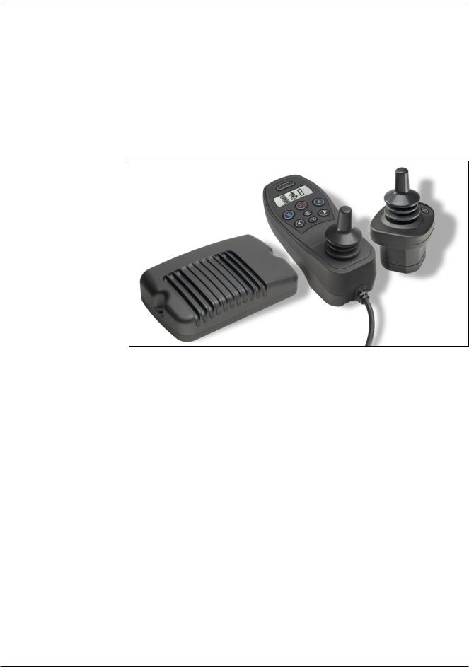
Fig. 1 Curtis enAble® 40 Powerchair Control System: powerbase (1740),
user handcontrol (1741), attendant control (1742).
OVERVIEW
The Curtis enAble® 40 Powerchair Control System provides outstanding versatility packaged in an easy-to-install, easy-to-use set of three components: a powerbase (motor controller) with optional seat actuators and lights, an ergonomic handcontrol with an intuitive icon LCD display, and an optional compact attendant control. The enAble® 40 provides the perfect solution for rear, mid, and front drive powerchairs. With its advanced seating control, it will also be the right fit for many Rehab chair configurations.
Like all Curtis motor control products, the enAble® 40 system offers superior control of drive performance, delivering a ride that is smooth and responsive in all modes: acceleration, deceleration, forward or backward, on smooth indoor surfaces, up a hill, or over gravel. Key features include
Powerbase:
Best-in-market drive feel and control for front-, mid-, and rear-wheel drive chairs.
Full 50 and 75 amp power ratings in a rugged, compact, and sealed enclosure.
Revolutionary MyChair™ parameter tunes the overall chair feel to fit each user’s unique needs — with a single parameter.
Patented Auto-Trim automatically and continuously corrects steering alignment, which can be thrown off by tire, motor, and gearbox wear and replacement.
Integration of lights and actuators provides these options at a minimum cost and without installation of additional wiring or modules.
Four independent configurations in each powerbase, with every parameter stored.
Curtis enAble® 40-Series Manual, Rev. B |
1 |

1 — OVERVIEW
Three flexible Multi-Function input pins for advanced seat actuator inhibits, speed limiting, and swivel chair functions usually found only on high-end systems.
Powerbase software is upgradable in the field or in the factory.
Onboard or offboard charging up to 12 amps accommodates high capacity batteries.
Compatible with the 1311 and 1314 programmers.
User handcontrol:
Stylish and ergonomic design.
Intuitive at-a-glance icons on LCD display with backlight, viewable in any lighting.
Three keypad configurations that match the application.
Nine programmable speed modes are quickly and easily accessible while driving.
Industry standard 3-pin XLR charger/programmer port.
Key-lock function to lock out unwanted drivers.
Rugged and flexible communications cable.
Field replaceable keypad, joystick, and communications cable.
Attendant control:
Easily connected to the system, with plug-in-line autoconnect feature.
Programmable takeover control.
Field-replaceable keypad, joystick, and communications cable.
The 40-Series introduces a number of unique features. Here are some brief descriptions.
Configurations
The powerbase stores four “configurations” — which are complete setups with data settings for every parameter. This means the OEM can have four configurations in one product—in effect, four products in one. The dealer can stock just one “4-in-1” model and use the Configuration parameter to select the most appropriate data block for each chair and each customer.
Each configuration is a complete setup, including two profiles for each. This means the 1740 actually holds eight different ready-made setups.
2 |
Curtis enAble® 40-Series Manual, Rev. B |

1 — OVERVIEW
Profiles
Each configuration in the 40-Series has two complete operational Profiles, each with its own speed, acceleration, and other response parameters. The Profiles are used two ways:
•MyChair™ — where Profiles 1 and 2 can be blended to provide a range of “feels,” through very simple and safe programming.
•Swivel Chair Mode — where Multi-Function Input 3 selects between Profile 1 or Profile 2.
MyChair™
TheMyChair™ functionprovidesaveryfastandsimplifiedwayforthetherapist to custom tune a chair to a specific user. With this one parameter, the therapist can adjust the aggressiveness and speed of the chair to suit the situation.
MyChair™ works by blending the key parameters from Profiles 1 and 2 as the MyChair™ parameter is adjusted from 1.0 (Profile 1) to 2.0 (Profile 2) in 0.1 steps (for 11 different “blends”). Normally the OEM sets the parameters of Profile 1 for a slower and less responsive chair and Profile 2 to the fastest and most responsive settings. By adjusting the MyChair™ parameter, the therapist caneasilyselectbetweenfactory-determinedsafeminimumandmaximumdrive configurations without understanding the details of chair stability, compensation, turn control, etc.
Swivel Chair
The Swivel Chair feature allows the Mode/Seat input to select between Profiles 1 and 2 while automatically switching the motor drive directions and wheel position parameters, for chairs that have a two-position seat. These chairs provide front-wheel drive for high speed outdoor mode and rear-wheel drive for indoor mode by simply rotating the seat 180 degrees.
MyChair™ does not work in Swivel Chair mode. Profile 1 is used when the switch is open and Profile 2 when the switch is closed.
Selectable Speed Modes
The therapist can select from 2 to 9 different speed modes for the user to access with the up/down speed mode buttons on the handcontrol. The therapist can set each speed mode independently in a linear or non-linear progression. This allows the therapist and user to select just the right number and speed for all conditions of driving. Some need only “indoor” and “outdoor” modes while other users prefer to use three or four different speed modes just around the normal walking pace to make travel with pedestrian friends and family easier.
Curtis enAble® 40-Series Manual, Rev. B |
3 |

1 — OVERVIEW
Multi-Function Inputs
The 40-Series introduces a level of seat and vehicle speed limiting/inhibit modes normally found on only the highest end Rehab systems. Three MultiFunction Inputs on the powerbase plus the Inhibit on the handcontrol charger port allow for flexible charger configurations (onboard/offboard), seat actuator inhibits in one or both directions, and up to four separate speed limits linked to these inputs.
Possible applications include:
•Inhibit drive and lock out tilt back (but not height or tilt forward) for an offboard charger.
•Limit the drive speed when the seat is tilted, with a second limit if the seat is raised.
•Provide an end-of-travel for any seat function.
•Lock out lift when the seat is reclined.
•Add a variable speed limit based on a seat tilt pot or seat height pot.
Auto-Trim
As the chair is used the gearbox, motor brushes, and tires wear. This adversely affects the straight-line drive performance and “trim” of the chair. The AutoTrim feature continuously monitors the driving behavior of the chair and corrects the trim automatically to provide consistent straight-line performance over the lifetime of the chair.
Dynamic Turn Radius Control
As the chair drives faster, its momentum increases dramatically and making quick sharp corners can upset the balance and steering feel of the chair. The Curtis proprietary Dynamic Turn Radius Control tempers the aggresssiveness of the steering as a function of speed to provide an always-in-control feel at every speed and through every turn.
Familiarity with your Curtis enAble® Powerchair Control System will help you install and operate it properly. We encourage you to read this manual carefully. If you have questions, please contact the Curtis office nearest you.
4 |
Curtis enAble® 40-Series Manual, Rev. B |
2 — INSTALLATION & WIRING
2
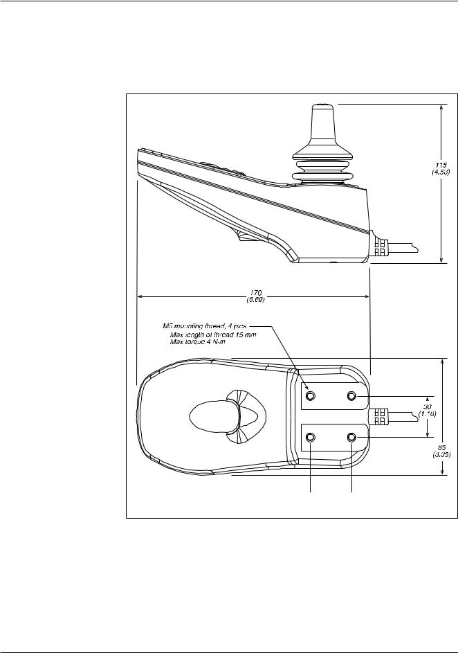
Fig. 2 Mounting dimensions, Curtis 1740 powerbase.
INSTALLATION AND WIRING
INSTALLING THE 40-SERIES SYSTEM
The 40-Series modules—powerbase, user handcontrol, and attendant con- trol—have been designed for convenient installation.
Mounting the 1740 Powerbase
The powerbase is easily mounted to the chair by means of two bolts, and can be oriented in any position.
Dimensions in millimeters (and inches)
A groove on the underside of the powerbase simplifies alignment when the powerbase is mounted on a tube, and provides stability.
Curtis enAble® 40-Series Manual, Rev. B |
5 |
2 — INSTALLATION & WIRING
Mounting the 1741 Handcontrol
Brass inserts in the user handcontrol allow it to be securely mounted and removed/reinstalled many times. The handcontrol is designed to fit both tube and plate mounting systems.
Fig. 3 Mounting dimensions, Curtis 1741 user handcontrol.
Dimensions in millimeters (and inches)
Curtis enAble® 40-Series Manual, Rev. B |
6 |
2 — INSTALLATION & WIRING
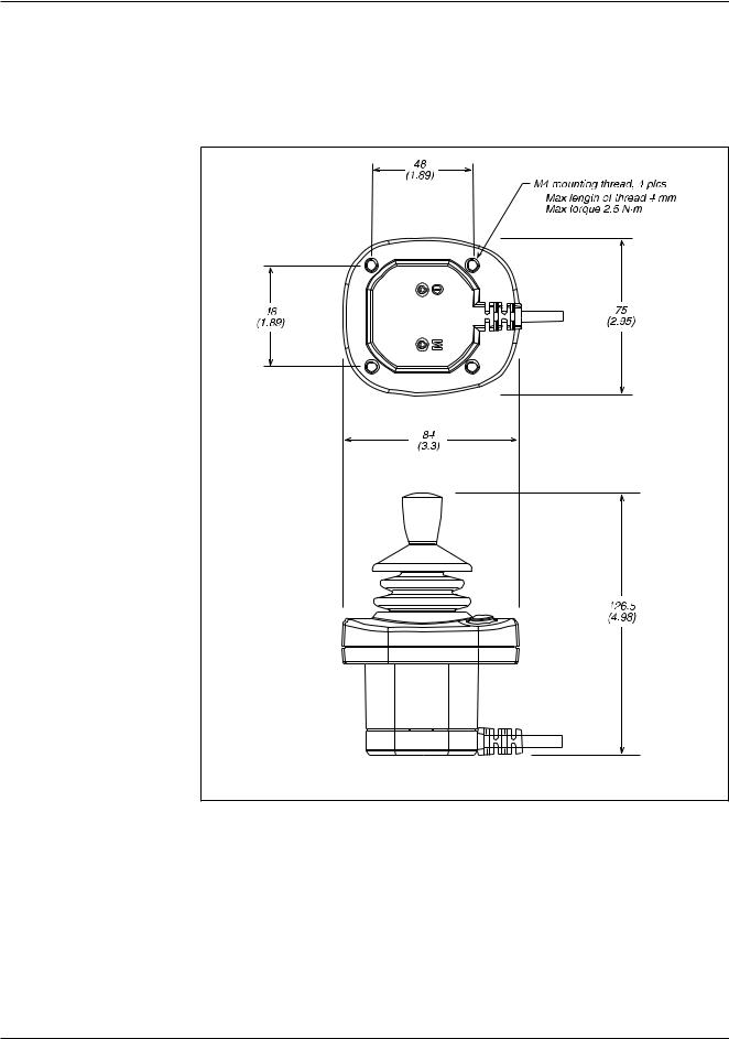
Mounting the 1742 Attendant Control
Like the handcontrol, the attendant control has brass inserts that allow it to be securely mounted and removed/reinstalled many times. The field replaceable cable can be rotated to either of two positions, fore and aft.
Fig. 4 Mounting dimensions, Curtis 1742 attendant control.
Dimensions in millimeters (and inches)
Curtis enAble® 40-Series Manual, Rev. B |
7 |
2 — INSTALLATION & WIRING
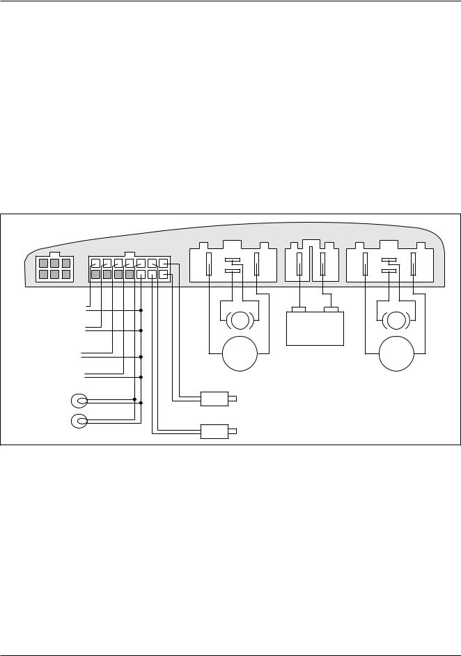
POWERBASE WIRING
Wiring for the 1740 powerbase is shown in Figure 5. The connections to the 14-pin connector are optional, depending on the level of functionality desired. For use with the simplest handcontrol (the basic drive-only version), no logic connections are required; for use with the full featured handcontrol (drive with lights and seat actuators), all the connections shown in Figure 5 are required. Additionalfeaturescanbeaddedtothesystembywiringadditionalcomponents to the Multi-Function pins (4–7); see Figure 6.
Themotorandbatteryconnectorhousingshavebeenspecificallydesigned for the enAble 40 system and must be purchased directly from your Curtis dealer or sales representative.The electrical connectors are standard AMP parts. Curtis also provides a kit with all the parts required to connect the high power wiring to the powerbase. See Appendix C for part numbers.
4 |
8 |
|
|
1 |
1 |
Rear L Turn 
Rear R Turn 
Front L Turn 
Front R Turn 
Running Lights
M1 |
– BATT + |
M2 |
M1 |
M2 |
Actuator 1
Actuator 2
Fig. 5 Basic wiring diagram, Curtis 1740 powerbase.
14-pin logic connector
The mating connector is 14-pin Molex Mini-Fit Junior, p/n 39-01-2140. You should use the matching Molex pins, p/n 44476-3112, which are suitable for high current, and 18–24 AWG wire. The pin-out is as follows:
Pin 1 Seat Motor 1+ |
Pin |
8 |
Seat Motor 1- |
|
Pin 2 Seat Motor 2+ |
Pin |
9 |
Seat Motor 2- |
|
Pin 3 |
B+ |
Pin 10 |
Running Lights - |
|
Pin 4 |
B- |
Pin 11 |
Front Right Turn - |
|
Pin 5 Multi-Function Input 1 |
Pin 12 |
Front Left Turn - |
||
Pin 6 |
Multi-Function Input 2 |
Pin 13 |
Rear Right Turn - |
|
Pin 7 |
Multi-Function Input 3 |
Pin 14 |
Rear Left Turn - |
|
8 |
Curtis enAble® 40-Series Manual, Rev. B |

2 — INSTALLATION & WIRING
Fig. 6 Wiring for the
Multi-Function inputs.
Molex High Current Contacts must be used for onboard charging through this connector. Allowable current is 12 amps continuous.
Curtis enAble® 40-Series Manual, Rev. B |
9 |
2 — INSTALLATION & WIRING
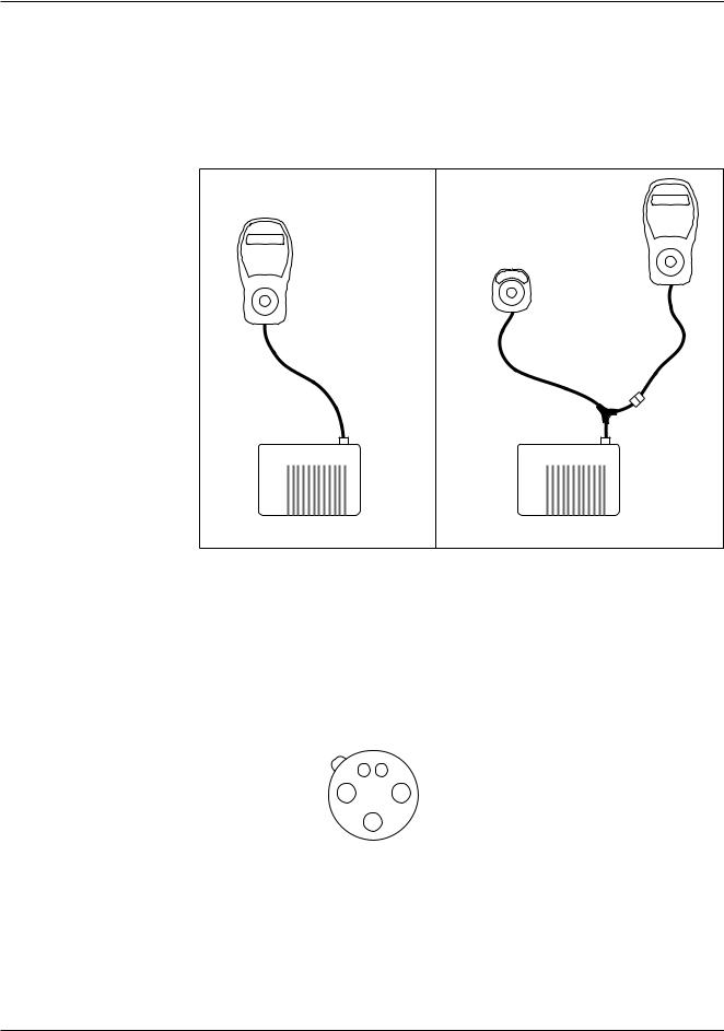
Fig. 7 Connecting the control modules to the powerbase.
CONNECTING THE CONTROL MODULES
The communications cable on the 1741 user handcontrol and on the 1742 attendant control each terminate in a plug that fits into the powerbase’s 6-pin connector. The attendant control’s cable includes a Y-junction into which the user handcontrol’s cable connects, as shown in Figure 7.
1741
HANDCONTROL
1742 ATTENDANT CONTROL
1740 POWERBASE |
1740 POWERBASE |
5-pin charger/programmer port
The user handcontrol has a 5-pin port that accommodates a battery charger and a 1311 programmer (although not at the same time). The charger plug’s three pins fit into sockets 1, 2, and 3. The programmer plug’s two pins fit into sockets 4 and 5. Both plugs are designed to snap securely into the port.
(view looking |
4 |
5 |
|
|
|
into the port) |
|
|
|
2 |
1 |
|
|
3 |
Pin 1 B+
Pin 2 B-
Pin 3 |
Inhibit (active to ground/B-) |
Pin 4 |
TXD |
Pin 5 |
RXD |
Allowable current for a charger in this port is 8 amps continuous (12 amps peak). The inhibit pin (pin 3) halts all chair travel during charging. Additionally,
it can prevent specific actuator movements.
10 |
Curtis enAble® 40-Series Manual, Rev. B |

|
|
3 — USER HANDCONTROL |
|
|
|
3 |
USER HANDCONTROL |
|
(1741) |
||
The 40-Series handcontrol is designed to be user-friendly. The keypad buttons |
||
are responsive and clearly marked. The LCD display is crisp and clear, with intuitive icons and backlighting to enhance daytime and nighttime readability. The communication cable is thin, flexible, and field replaceable.
The handcontrol is the main user interface to the control system. All user commands come from the handcontrol’s keypad and joystick.The handcontrol is also the information center of the system. All faults, errors, limits, and status (operational characteristics) are displayed on its LCD display.
JOYSTICK
Moving the joystick straight forward and straight backward proportionately controls the travel speed of the chair. Neutral (center position) always requests no movement. Two deadbands, one around neutral and one at the full throw (againstthegate),provideazoneateachextremewheresmallmovements—caused by tremors, bumps, etc.—do not cause changes in vehicle speed.
Moving the joystick right and left (side to side) proportionately controls the turning radius and turn rate of the vehicle.
KEYPADS
Three versions of the handcontrol are available: Drive Only, Drive with Actuators, and Drive with Actuators and Lights.
Three keypad layouts correspond to the three versions:
Drive Only (4 buttons):
■ on/off, ■ horn, ■ speed up, ■ speed down.
Drive + Actuators (6 buttons):
■ on/off, ■ horn, ■ speed up, ■ speed down, ■ seat mode 1, ■ seat mode 2.
Drive + Actuators + Lights (8 buttons):
■ on/off, ■ horn, ■ speed up, ■ speed down, ■ L turn, ■ R turn, ■ headlights, ■ mode. The functions of the various buttons are described in the following pages.
Curtis enAble® 40-Series Manual, Rev. B |
11 |
3 — USER HANDCONTROL
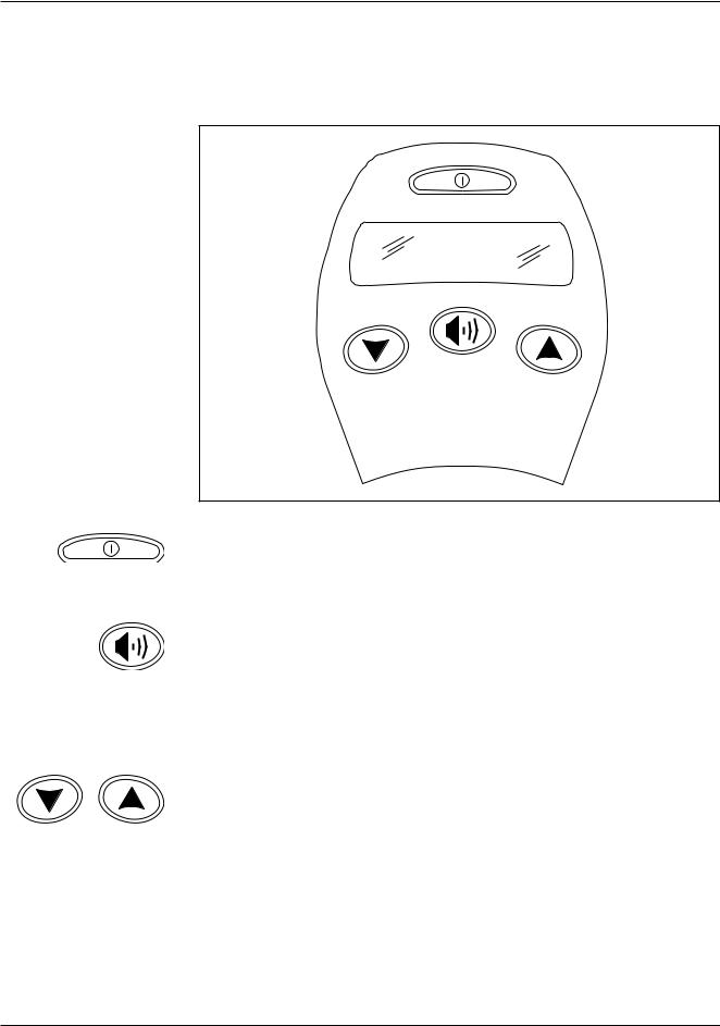
Fig. 8a Keypad for basic Drive Only handcontrol; these buttons are standard on all the keypads.
Drive Only (4-button keypad)
The Drive Only keypad has four buttons: On/Off, Horn, Speed Up, and Speed Down. These four basic buttons are standard on all the keypad versions.
On/Off Button
The Power On/Off button is located at the top of the keypad, above the display. This button can also be used to lock the chair; see Handcontrol menu, page 24.
Horn Button
Pressing the Horn button sounds the horn. The horn is generally used to alert nearby pedestrians to the oncoming chair. Beyond this basic function, the horn can be programmed to provide several other functions: a back-up alarm, audible feedback for button presses, and an error code beep (see Sound & Display menu, page 27).
Speed Down and Speed Up Buttons
The Speed Down and Speed Up buttons are used to select the speed mode. Pressing the Speed Down button selects the next lower speed mode each time it is pressed, while pressing the Speed Up button selects the next higher speed mode.The speed modes function like incremental positions on a variable speed pot.
12 |
Curtis enAble® 40-Series Manual, Rev. B |
3 — USER HANDCONTROL
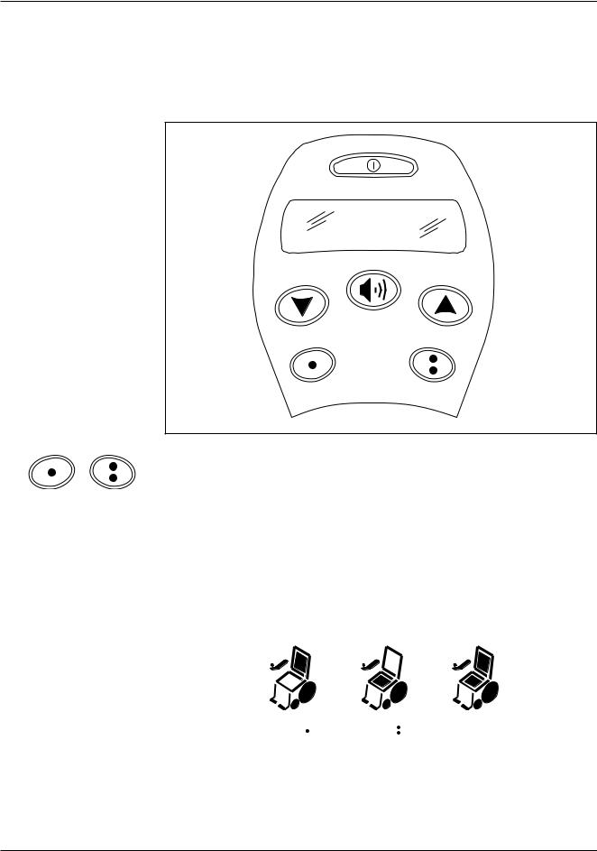
Fig. 8b Keypad for the Drive + Actuators handcontrol.
Drive with Actuators (6-button keypad)
This keypad’s six buttons are the standard four (On/Off, Horn, Speed Up, Speed Down) plus two buttons to activate the two actuator modes. The mode buttons show one dot (for Mode 1) and two dots (for Mode 2).
Actuator Mode Buttons
With this handcontrol, there’s a button for each mode: Actuator Mode 1 and Actuator Mode 2. The joystick must be in neutral before pressing an actuator mode button.
Pressing a mode button causes the LCD chair icon’s outline segments to illuminate; the fill-in portion of the specific actuator illuminates to show which actuator is active (Actuator 1 or Actuator 2). Pressing both Mode buttons simultaneously causes both actuators to be active. In this example, Actuator 1 is the seatback and Actuator 2 is the seat. For programming, see Seat menu, page 28.
MODE 1 |
MODE 2 |
BOTH |
BUTTON ( ) |
BUTTON ( ) |
MODE BUTTONS |
PRESSED |
PRESSED |
PRESSED |
Once in actuator mode via one of the mode buttons, moving the joystick to the right will cycle through the options (Mode 1, Mode 2, Both, Mode 1....) To exit actuator mode, either move the joystick to the left or press the button corresponding to the active mode again.
Curtis enAble® 40-Series Manual, Rev. B |
13 |
3 — USER HANDCONTROL
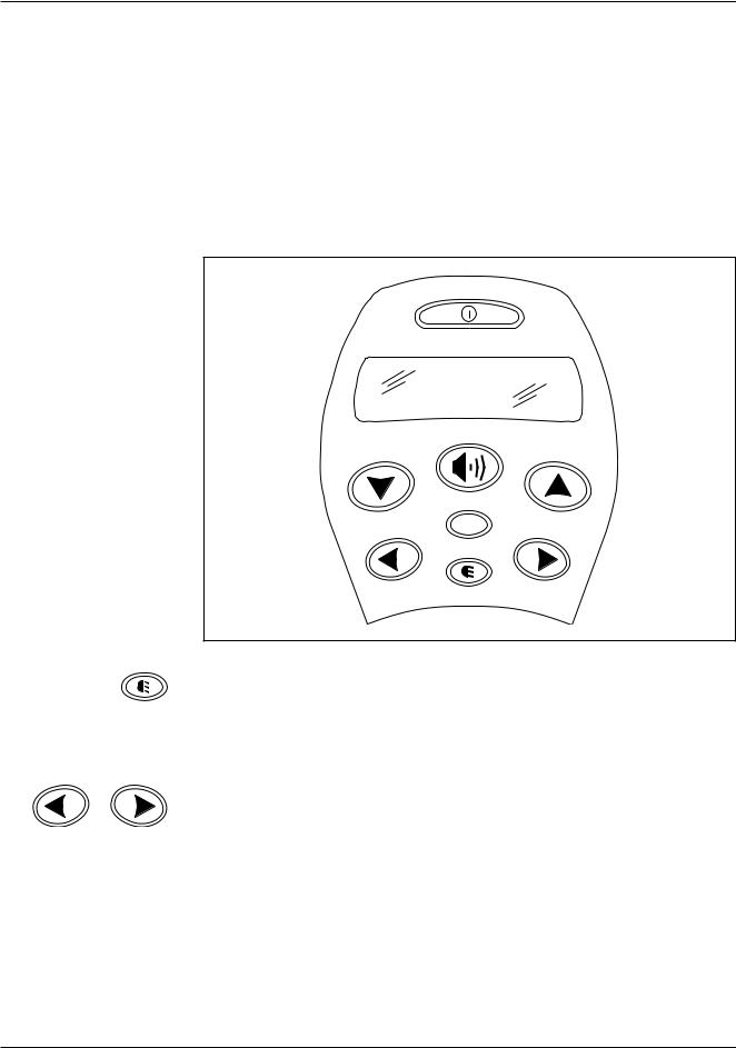
Fig. 8c Keypad for the Drive + Actuators + Lights handcontrol.
Drive with Actuators and Lights (8-button Keypad)
This keypad’s eight buttons are the standard four (On/Off, Horn, Speed Up, Speed Down) plus a Running Lights button, two buttons for the turn indicators (left and right), and an Actuator Mode button.
The hazard lights (i.e., flashing left and right turn signals, front and rear) are activated by pressing both turn indicator buttons simultaneously. They will continue to flash even if the system is powered down. To turn off the hazard lights, press either indicator button again.
Both actuator modes are accessed with the single Mode button.
M
Running Lights Button
Pressing the Running Lights button turns on the headlamps and any other running lights on the chair. Pressing the button again turns them off. When the lights are on, the running lights icon in the LCD is illuminated.
Turn Indicator Buttons
The Left and Right Turn Indicator buttons activate the corresponding turn indicators. Pressing the turn indicator button again will turn the indicator off. Also, note that pressing the opposite turn indicator button will cancel the first indicator and activate the new one.
The turn indicator icons in the LCD flash in synchronicity with the actual turn indicator lights.
14 |
Curtis enAble® 40-Series Manual, Rev. B |
 Loading...