


Safe Operation Practices • Set-Up • Operation • Maintenance • Service • Troubleshooting • Warranty
Operator’s Manual
Two-Stage Snow Thrower — 524 SWE
 WARNING
READ AND FOLLOW ALL SAFETY RULES AND INSTRUCTIONS IN THIS MANUAL
BEFORE ATTEMPTING TO OPERATE THIS MACHINE.
FAILURE TO COMPLY WITH THESE INSTRUCTIONS MAY RESULT IN PERSONAL INJURY.
CUB CADET LLC, P.O. BOX 361131 CLEVELAND, OHIO 44136-0019
Printed In USA |
Form No. 769-03344A |
|
(December 2, 2007) |

To The Owner
Thank You
Thank you for purchasing a GardenSnow ThrowerTractormanufacturedby CubTroyMTD-CadetBiltLLCLLC.ItLLCwas.It. wItwascarefullyfullyc enginngineeredertoeredprovidetotoprovidexcellexc ntellent performance when properly operated and maintained.
Please read this entire manual prior to operating the equipment. It instructs you how to safely and easily set up, operate and maintain your machine. Please be sure that you, and any other persons who will operate the machine, carefully follow the recommended safety practices at all times. Failure to do so could result in personal injury or property damage.
All information in this manual is relative to the most recent product information available at the time of printing. Review this manual frequently to familiarize yourself with the machine, its features and operation. Please be aware that this Operator’s Manual may cover a range of product specifications for various models. Characteristics and features discussed and/or illustrated in this manual may not be applicable to all models. CubTroyMTD-CadetBiltLLCLLC LLCreserveseservesthe righttherightto changeto changeproductproductspecifications,designsigands andequipmentequipmentwithoutwithoutnoticenoticeand andwithoutwithoutincurringincurringobligationobligation. .
1
This product has met the rigid safety standards of the Outdoor Power Equipment Institute and an independent testing laboratory. If you have any problems or questions concerning the themachine,machine,phonephonea authoyourizedlocalTroyaCuthorizeddealerb-BiltCads rviceMTDdealerserviceor contactordealercontactus orusdirectlycontactdirectly.C.usbTroydirecCadeBilt’sCustomerCustomerSupportSupporttelephonenumbers,b- ly. MTD’s telephon rs, numbers,website addrewebssiteandaddressmailingandaddressmailingcanaddressbe foundcanonbethisfoundpageon. thisWe wpantgeto.Wensurewantytoensurecompleteyour satisfactionsatisfactionallcomplete timesat. all
times.
Throughout this manual, all references to right and left side of the machineThroughoutarethisobservedmanual,fromall reftherencesoperatingto rightpositionand left. side of the
machine are observed from the operating position
The engine manufacturer is responsible for all engine-related issuesThe engwinethregardsmanufacturto performance,isresponsiblepowerfor-rating,allenginespecifications,-related warrantyissues withandregaserdsviceto. Plperformance,aserefer topowtheenginer-rating,manufacturer’sspecifications, Owner’s/Operator’swarranty and serviceManual,.Please packedreferto separatelytheenginewithmanufacturer’syour machine,Owner’s/Operator’sfor more informManuationl,packed. separately with your machine, for more information.
Table of Contents
Safe Operation Practices......................................... |
3 |
Engine Maintenance |
...............................................18 |
Assembly & Set-Up................................................... |
6 |
Service..................................................................... |
20 |
Controls and Features............................................ |
10 |
Troubleshooting..................................................... |
23 |
Operation................................................................ |
13 |
Replacement Parts................................................. |
24 |
Maintenance & Adjustment.................................. |
15 |
|
|
Record Product Information
Before setting up and operating your new equipment, please locate the model plate on the equipment and record the information in the provided area to the right. You can locate the model plate by standing at the operator’s position and looking down at the rear of the frame.deck Thisinformationwill.bebenecessary,sary, should you seek technical support via our web site,orCustomerwith your localSupportCubDepartment,Cadet d aleror. with a local authorized service dealer.
Model Number
Serial Number
Serial Number
Customer Support
If youPleasehavedodifficultyNOT returnassemblingthe machinethis productto the retaileror haveoranydealerquestionswithoutregardingfirst contactingthe controls,our Customeroperation,SupportmaintDepartmentnce of .
this machine, you can seek help from the experts. Choose from the options below:
If you have difficulty assembling this product or have any questions regarding the controls, operation, or maintenance of this◊ machine,Visit us onyouthecanwebseekat wwwhelp.cubcadfrom thetexperts.com . Choose from the options below:
◊VisitCallLocateusCustomeryouron then webarestSupportatCubwwwCadetRepresen.troybiltmtdproductsDealer.ativecom at(877).com(800)282965-8684-4CUB
◊CallLocateWrite Customeryourat Cubn arestCadetSupportCubLLCCadetRepresentative• P.O. DealerBox361131at(877)•(800)Cleveland,28280028-8684-5500731OHor• 44136(330)-2205580019-72204683
◊Write us at MTDTroyCub-CadetBiltLLCLLC• PLLC.O•.PBox.•OP..OBox36113113. Box 361• Cleveland,veland,131• • OHOH•44136OH• 44136• 44136-0019-0019-0019
Important Safe Operation Practices |
2 |
|
|
|
|
WARNING! This symbol points out important safety instructions which, if not followed, could endanger the personal safety and/or property of yourself and others. Read and follow all instructions in this manual before attempting to operate this machine. Failure to comply with these instructions may result in personal injury.
When you see this symbol. HEED ITS WARNING!
California Proposition 65
WARNING! Engine Exhaust, some of its constituents, and certain vehicle components contain or emit chemicals known to State of California to cause cancer and birth defects or other reproductive harm.
DANGER: This machine was built to be operated according to the safe operation practices in this manual. As with any type of power equipment, carelessness or error on the part of the operator can result in serious injury. This machine is capable of amputating fingers, hands, toes and feet and throwing foreign objects. Failure to observe the following safety instructions could result in serious injury or death.
Training
1.Read, understand, and follow all instructions on the machine and in the manual(s) before attempting to assemble and operate. Keep this manual in a safe place for future and regular reference and for ordering replacement parts.
2.Be familiar with all controls and their proper operation. Know how to stop the machine and disengage them quickly.
3.Never allow children under 14 years of age to operate this machine. Children 14 and over should read and understand the instructions and safe operation practices in this manual and on the machine and be trained and supervised by an adult.
4.Never allow adults to operate this machine without proper instruction.
5.Thrown objects can cause serious personal injury. Plan your snow-throwing pattern to avoid discharge of material toward roads, bystanders and the like.
6.Keep bystanders, helpers, pets and children at least 75 feet from the machine while it is in operation. Stop machine if anyone enters the area.
7.Exercise caution to avoid slipping or falling, especially when operating in reverse.
Preparation
Thoroughly inspect the area where the equipment is to be used. Remove all doormats, newspapers, sleds, boards, wires and other foreign objects, which could be tripped over or thrown by the auger/impeller.
1.Always wear safety glasses or eye shields during operation and while performing an adjustment or repair to protect your eyes. Thrown objects which ricochet can cause serious injury to the eyes.
2.Do not operate without wearing adequate winter outer garments. Do not wear jewelry, long scarves or other loose clothing, which could become entangled in moving parts. Wear footwear which will improve footing on slippery surfaces.
3.Use a grounded three-wire extension cord and receptacle for all machines with electric start engines.
4.Adjust collector housing height to clear gravel or crushed rock surfaces.
5.Disengage all control levers before starting the engine.
6.Never attempt to make any adjustments while engine is running, except where specifically recommended in the operator’s manual.
7.Let engine and machine adjust to outdoor temperature before starting to clear snow.

Safe Handling of Gasoline
To avoid personal injury or property damage use extreme care in handling gasoline. Gasoline is extremely flammable and the vapors are explosive. Serious personal injury can occur when gasoline is spilled on yourself or your clothes which can ignite. Wash your skin and change clothes immediately.
a.Use only an approved gasoline container.
b.Extinguish all cigarettes, cigars, pipes and other sources of ignition.
c.Never fuel machine indoors.
d.Never remove gas cap or add fuel while the engine is hot or running.
e.Allow engine to cool at least two minutes before refueling.
f.Never over fill fuel tank. Fill tank to no more than ½ inch below bottom of filler neck to provide space for fuel expansion.
g.Replace gasoline cap and tighten securely.
h.If gasoline is spilled, wipe it off the engine and equipment. Move machine to another area. Wait 5 minutes before starting the engine.
i.Never store the machine or fuel container inside where there is an open flame, spark or pilot light (e.g. furnace, water heater, space heater, clothes dryer etc.).
j.Allow machine to cool at least 5 minutes before storing.
k.Never fill containers inside a vehicle or on a truck or trailer bed with a plastic liner. Always place containers on the ground away from your vehicle before filling.
l.If possible, remove gas-powered equipment from the truck or trailer and refuel it on the ground. If this is not possible, then refuel such equipment on a trailer with a portable container, rather than from a gasoline dispenser nozzle.
m.Keep the nozzle in contact with the rim of the fuel tank or container opening at all times until fueling is complete. Do not use a nozzle lock-open device.
Operation
1.Do not put hands or feet near rotating parts, in the auger/ impeller housing or chute assembly. Contact with the rotating parts can amputate hands and feet.
2.The auger/impeller control lever is a safety device. Never bypass its operation. Doing so makes the machine unsafe and may cause personal injury.
3.The control levers must operate easily in both directions and automatically return to the disengaged position when released.
4.Never operate with a missing or damaged chute assembly. Keep all safety devices in place and working.
5.Never run an engine indoors or in a poorly ventilated area. Engine exhaust contains carbon monoxide, an odorless and deadly gas.
6.Do not operate machine while under the influence of alcohol or drugs.
7.Muffler and engine become hot and can cause a burn. Do not touch. Keep children away.
8.Exercise extreme caution when operating on or crossing gravel surfaces. Stay alert for hidden hazards or traffic.
9.Exercise caution when changing direction and while operating on slopes.
10.Plan your snow-throwing pattern to avoid discharge towards windows, walls, cars etc. Thus, avoiding possible property damage or personal injury caused by a ricochet.
11.Never direct discharge at children, bystanders and pets or allow anyone in front of the machine.
12.Do not overload machine capacity by attempting to clear snow at too fast of a rate.
13.Never operate this machine without good visibility or light. Always be sure of your footing and keep a firm hold on the handles. Walk, never run.
14.Disengage power to the auger/impeller when transporting or not in use.
15.Never operate machine at high transport speeds on slippery surfaces. Look down and behind and use care when backing up.
16.If the machine should start to vibrate abnormally, stop the engine, disconnect the spark plug wire and ground it against the engine. Inspect thoroughly for damage. Repair any damage before starting and operating.
17.Disengage all control levers and stop engine before you leave the operating position (behind the handles). Wait until the auger/impeller comes to a complete stop before unclogging the chute assembly, making any adjustments, or inspections.
18.Never put your hand in the discharge or collector openings. Always use the clean-out tool provided to unclog the discharge opening. Do not unclog chute assembly while engine is running. Shut off engine and remain behind handles until all moving parts have stopped before unclogging.
19.Use only attachments and accessories approved by the manufacturer (e.g. wheel weights, tire chains, cabs etc.).
20.When starting engine, pull cord slowly until resistance is felt, then pull rapidly. Rapid retraction of starter cord
(kickback) will pull hand and arm toward engine faster than you can let go. Broken bones, fractures, bruises or sprains could result.
21.If situations occur which are not covered in this manual, use care and good judgment. Contact Customer Support for assistance and the name of your nearest servicing dealer.
Section 2 — Important Safe Operation Practices
Maintenance & Storage
1.Never tamper with safety devices. Check their proper operation regularly. Refer to the maintenance and adjustment sections of this manual.
2.Before cleaning, repairing, or inspecting machine disengage all control levers and stop the engine. Wait until the auger/impeller come to a complete stop. Disconnect the spark plug wire and ground against the engine to prevent unintended starting.
3.Check bolts and screws for proper tightness at frequent intervals to keep the machine in safe working condition. Also, visually inspect machine for any damage.
4.Do not change the engine governor setting or over-speed the engine. The governor controls the maximum safe operating speed of the engine.
5.Snow thrower shave plates and skid shoes are subject to wear and damage. For your safety protection, frequently check all components and replace with original equipment manufacturer’s (OEM) parts only. “Use of parts which do not meet the original equipment specifications may lead to improper performance and compromise safety!”
6.Check control levers periodically to verify they engage and disengage properly and adjust, if necessary. Refer to the adjustment section in this operator’s manual for instructions.
7.Maintain or replace safety and instruction labels, as necessary.
8.Observe proper disposal laws and regulations for gas, oil, etc. to protect the environment.
9.Prior to storing, run machine a few minutes to clear snow from machine and prevent freeze up of auger/impeller.
10.Never store the machine or fuel container inside where there is an open flame, spark or pilot light such as a water heater, furnace, clothes dryer etc.
11.Always refer to the operator’s manual for proper instructions on off-season storage.
12.Check fuel line, tank, cap, and fittings frequently for cracks or leaks. Replace if necessary.
13.Do not crank engine with spark plug removed.
Do not modify engine
To avoid serious injury or death, do not modify engine in any way. Tampering with the governor setting can lead to a runaway engine and cause it to operate at unsafe speeds. Never tamper with factory setting of engine governor.
Notice Regarding Emissions
Engines which are certified to comply with California and federal EPA emission regulations for SORE (Small Off Road Equipment) are certified to operate on regular unleaded gasoline, and
may include the following emission control systems: Engine Modification (EM) and Three Way Catalyst (TWC) if so equipped.
Spark Arrestor
Warning! This machine is equipped with an internal combustion engine and should not be used on or near any unimproved forest-covered, brush covered or grass-covered land unless the engine’s exhaust system is equipped with a spark arrester meeting applicable local or state laws (if any).
If a spark arrester is used, it should be maintained in effective working order by the operator. In the State of California the above is required by law (Section 4442 of the California Public Resources Code). Other states may have similar laws. Federal laws apply on federal lands.
A spark arrester for the muffler is available through your nearest engine authorized service dealer or contact the service department, P.O. Box 361131 Cleveland, Ohio 44136-0019.
Average Useful Life
According to the Consumer Products Safety Commission (CPSC) and the U.S. Environmental Protection Agency (EPA), this product has an Average Useful Life of seven (7) years, or 60 hours of operation. At the end of the Average Useful Life, buy a new machine or have the machine inspected annually by an authorized service dealer to ensure that all mechanical and safety systems are working properly and not worn excessively. Failure to do so can result in accidents, injuries or death.
warning! Your Responsibility—Restrict the use of this power machine to persons who read, understand and follow the warnings and instructions in this manual and on the machine.
SAVE THESE INSTRUCTIONS!
Section 2 — Important Safe Operation Practices
Assembly & Set-Up |
3 |
|
|
|
|
Contents of Carton |
|
• |
One Snow Thrower |
• |
Two Replacement Auger Shear Pins • |
One ProductSnowTecumsehThrowerRegistrationEngineOperMaCardtor’snual |
• |
One Snow Thrower Operator’s |
• |
One Tecumseh Engine Operator’s |
Manual |
|
||||
|
Manual |
|
Manual |
|
Assembly
Handle
1.Place the shift lever in the Forward-6 position
2.Observe the lower rear area of the snow thrower to be sure both cables are aligned with roller guides before pivoting the handle upward. See Fig. 3-1.
Figure 3-1
NOTE: Make certain the upper ends of each cable are seated properly in its bracket.
3.Secure the handle by tightening the plastic knob located on both the left and right sides of the handle. Remove and discard any rubber bands, if present. They are for packaging purposes only.
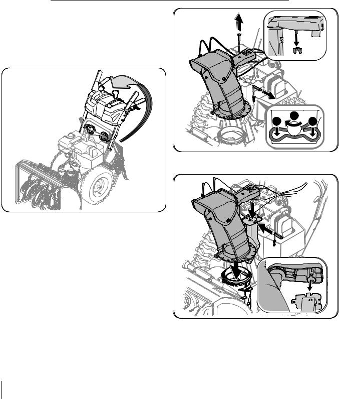
Chute Assembly
1.Remove wing nut and hex screw from chute control assembly and clevis pin and cotter pin from chute support bracket. Position the chute assembly (forward-facing) over the chute base. See Fig. 3-2.
2.Place chute assembly onto chute base and secure chute control assembly to chute support bracket with clevis pin and cotter pin removed earlier. See See Fig. 3-3.
2
1 1
Figure 3-2
Figure 3-3

3.Finish securing chute control assembly to chute support bracket with wing nut and hex screw removed earlier. See See Fig. 3-4.
Figure 3-4
4. Check that all cables are properly routed through the cable guide on top of the engine. See Fig. 3-5.
4.Check that all cables are properly routed through the cable guide on top of the engine. See Fig. 3-5.
Set3. -UpFinish securing chute control assembly to chute support bracket with wing nut and hex screw removed earlier.
ShearSeePinsSee Fig. 3-4.
4. Check that all cables are properly routed through the cable A pair of replacement auger shear pins and bow tie cotter pins
g ide on op of the engine. S e Fig. 3-5.
are included with your snow thrower. Store them in your snow thrower’s dash panel until needed. See Fig. 3-5.
Figure 3-6
Chute Clean-Out Tool
The chute clean-out tool is fastened to the top of the auger housing with a mounting clip and a cable tie at the factory. Cut the cable tie before operating the snow thrower. See Fig. 3-7.
Chute Clean-out Tool
Figure 3-5
Figure 3-7
Section 3 — Assembly & Set-Up
SetTire-PressureUp
Before operating, check tire pressure and reduce pressure in
Shear Pins
both tires to between 15 psi and 20 psi.
A pair of replacement auger shear pins and bow tie cotter pins NOTE: If the tire pressure is not equal in both tires, the machine are included with your snow thrower. Store them in your snow may not travel in a straight path and the shave plate may wear thrower’s dash panel until needed. See Fig. 3-6.
unevenly.
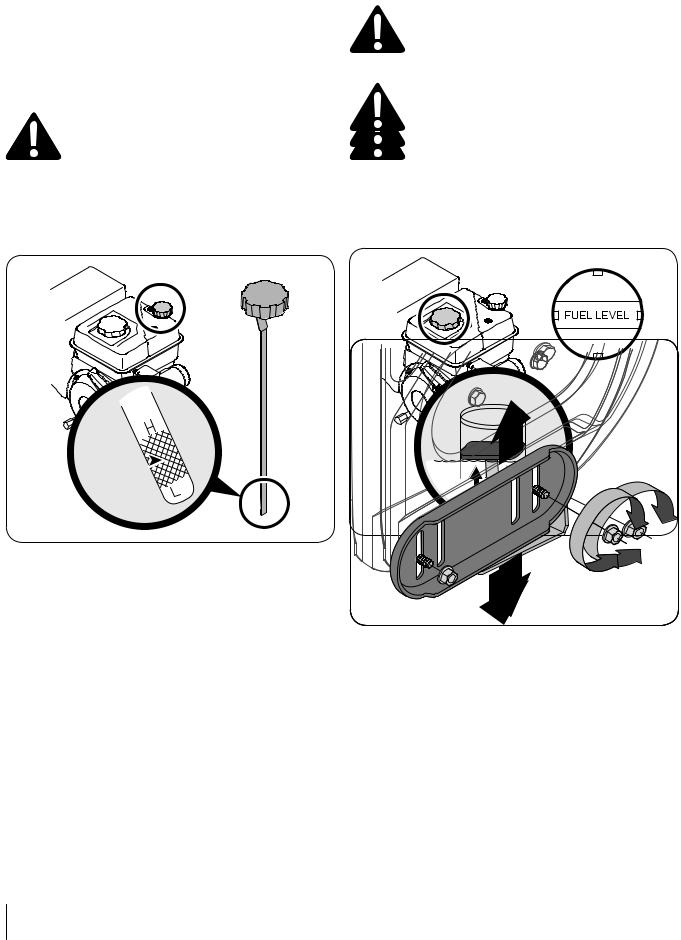
Checkingute Clean-Out Tool Gas & Oil FilOil-LevelUp
clean-out tool is fastened to the top of the auger Warning!CAUTION: TheUsengineextremeis shippedcare whenwithandlingoil the a mounting clip and a cable tie at the factory. Cut
gasoline. Gasolineengineis. Youextremelymust, however,flammablecheckand the oilvaporslevelareprior before operating the snow thrower. See Fig. 3-7.
explosive. Nevertooperatingfuel the machinethesnowindthroorsweror.Runningwhile thetheengineis hot or runningwith.Extinguinsufficientshcigarettes,oil can causecigarserious,pipeseanginedother sources of ignitiondamage. and void the engine warranty.
NOTE:ServiceBethesureengineto checkwiththegasolineengineandonoila levelas instructedurfacewithin thethe Tecumsehengine stoppedEngine. Operator’s Manual packed separately with
your snow thrower. Read instructions carefully.
1. Remove the oil filler cap/dipstick and wipe the dipstick NOTE:cleanYour. snowSeeFigthrower.3-8. is shipped with oil in the engine.
Fill between high  and low marks
Figure 3-8
However, you MUST check the oil level before operating. Refer to 2. Insert the cap/dipstick into the oil filler neck, but do not Tecumseh Engine Operator’s Manual for detailed instructions.
screw it in.
3.Remove the oil filler cap/dipstick. If the level is low, slowly add oil until oil level registers between high (H) and low (L), Fig. 5-1. Refer to the Engine Maintenance section for correct oil viscosity and engine oil capacity.
NOTE: Do not overfill. Overfilling with oil may result in engine smoking, hard starting or spark plug fouling.
4.Replace and tighten cap/dipstick firmly before starting engine.
AdjustmentsTiredingPressureFu l
operating,Warning!check tireUseprextremessure andcareducewh npressurehandlingin Skid Shoes gasolinebetween. Gasoline15 psi andis20extremelypsi. flammable and the
The snow throwervaporskidareshoesexplosiveare .adjustedNever fuelupwardthe machineat the factory tire pressure is not equal in both tires, the machine
for shipping purposesor. Adjustwhile themenginedownward,is hot orif runningdesired,.prior travelindoorsa straight path and the shave plate may wear
to operatingExtinguishthe snow throwcigarettes,r. cigars, pipes and other unevenly.
sources of ignition.
Caution: It is not recommended that you operate
-Up
this snow throwerWARNING!on graveAlwaysas it cankeepeasilyhandspickandupfeetandclearthrowof loose gravel,Warning!eqcauipmentsing personalmovingUse extremeinjurypartsor. Docdamagerenotwhenusetohandlingthepressurizedsnow
thrower andGasolinetartingsurroundingis extremelyfluid.propertysVa flammableare. flammableand the. vapors are
Never fuel the machine indoors or while the engine is
• For close snow removal on a smooth surface, raise skid hot or running. Extinguish cigarettes, cigars, pipes and other
shoes higher on the auger housing. 1sources. Cleanof ignitionaround. fuel fill before removing cap to fuel.
• Use a middle or lower position when the area to be cleared 2Service. A thefu lenginelevel indicatorwith gasois locatedine andinoiltheas instructedfuel tank. Fillin tankhe
is uneven, such as a gravel driveway
Tecumsehuntil Enginefuel reachesOperator’sthe fuelManuallevel indictor,packed separatelyFig. 3-9. Bewithcareful NOTE: If you choose to operate the snow thrower on a gravel your snotwtothroweroverfill..Read instructions carefully.
surface, keep the skid shoes in position for maximum clearance
Fuel Level Indicator
Top View
betweenFuel |
|
|
NOTE: |
in the engine. |
|
However, |
operating. Refer to |
|
Use automotive gasoline |
or low leaded to minimize |
|
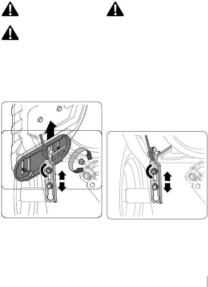
To adjust the skid shoes: |
for detailed instructions. |
|
Tecumseh Engine Operator’s |
||
combustion chamber deposits) with a minimum of 87 octane. |
||
1. |
Loosen the four hex nuts (two on each side) and carriage |
|
Gasoline with up to 10% ethanol or 15% MTBE (Methyl Tertiary |
||
|
|
3-8 |
|
bolts. Move skid shoesFigureto d sired position. See Fig. 3-8. |
|
Butyl Ether) can be used. Never use an oil/gasoline mixture or |
||
2. |
Make certain the entire bottom surface of skid sho is |
|
dirty gasoline. Avoid getting dirt, dust, or water in the fuel tank. |
||
|
against the ground to avoid uneven wear on the skid |
|
DO NOT use E85 gasoline. |
|
|
• |
shoes. |
|
Refuel in a well-ventilated area with the engine stopped. |
||
3.RetightenDo not smokenutsorandallowboltsflamessecurelyor sparks. in the area where the engine is refueled or where gasoline is stored.
•Do not overfill the fuel tank. After refueling, make sure the tank cap is closed properly and securely.
•Be careful not to spill fuel when refueling. Spilled fuel or fuel vapor may ignite. If any fuel is spilled, make sure the area is dry before starting the engine.
•Avoid repeated or prolonged contact with skin or breathing of vapor.
Section 3— Assembly & Set-Up
AugerdjustmentsControl
Warning! Prior to operating your snow thrower,
carefully read and follow all instructions below. Perform all adjustmentsthrowerto verifyskidyourshoessnowarethroweradjustedisupwardoperatingthesafelyfactoryand properly. purposes. Adjust them downward, if desired, prior
to operating the snow thrower.
Check the adjustment of the auger control as follows:
Caution: It is not recommended that you operate 1. When the auger control is released and in the disengaged
throwerthissnowon gravelthroweras itoncangraveleasilypickit canupeasilyndthrowpickup “up” position, the cable should have very little slack. It
andcausingthrowpersloosenalgravel,injurycausingordamageperstonaltheinjurysnow or should NOT be tight.
damagesurroundingto thepropertysnow thrower. and surrounding 2. In a well-ventilated area, start the snow thrower engine.
property.
• For close snow removal on a smooth surface, raise skid Refer to Starting the Engine on page 12. Make sure the
• shoesFor closehighersnowonremovalthe augeronhousingasmooth. surface, raise skid throttle is set in the FAST position.
shoes higher on the auger housing.
• Use a middle or lower position when the area to be cleared 3. While standing in the operator’s position (behind the snow
• isUseuneven,a middlesuchoraslowera gravelpositiondrivewaywhen the area to be cleared thrower), engage the auger.
is uneven, such as a gravel driveway
NOTE: If you choose to operate the snow thrower on a gravel 4. Allow the auger to remain engaged for approximately ten NOTE:surface,Ifkeepyouchoosethe skidtoshoopesratein positionthe snowforthrowermaximumon aclegravelrance
(10) seconds before releasing the auger control. Repeat this betwesurface,nkeepthe groundtheskidandshoestheinshavepositionplatefor. maximum clearance
several times.
between the ground and the shave plate. To adjust the skid shoes:
5. With the throttle control in the FAST (rabbit) position and To adjust the skid shoes:
1. theLoosenaugerthecontrolfour hexin thenutsdisengag(two on edach“up”side)position,and carriagewalk to
1.theLboosenltsfront. Moveheof fourtheskidmachinehexshoesnutos. (twodesiredon positioneachside). SeeandFigcarriage.3-8.
bolts. Move skid shoes to desired position. See Fig. 3-10. 62. ConfirmMake certainthat the augerentire hasbottomsurfaceco pletely stoppedofskid shrotatingeis
Auger Control
Warning! Prior to operating your snow thrower, carefullynd followreadallandinstructionsfollow all belowinstructions.Performbelowall . Perfotoverifymallyouradjustmentssnow throwerto verifyis operatingyour snowsafelythrowerand is operating safely and properly.
Check the adjustment of the auger control as follows:
1.When the auger control is released and in the disengaged “up” position, the cable should have very little slack. It should NOT be tight.
2.In a well-ventilated area, start the snow thrower engine. Refer to Starting the Engine on page 132. Make sure the throttle is set in the FAST position.
3.While standing in the operator’s position (behind the snow thrower), engage the auger.
4.Allow the auger to remain engaged for approximately ten (10) seconds before releasing the auger control. Repeat this several times.
5.With the throttle control in the FAST (rabbit) position and the auger control in the disengaged “up” position, walk to the front of the machine.
6.Confirm that the auger has completely stopped rotating and shows NO signs of motion. If the auger shows ANY signs of rotating, immediately return to the operator’s position and shut off the engine. Wait for ALL moving parts to stop before re-adjusting the auger control.
7.To readjust the control cable, loosen the upper hex nut on the auger cable bracket. See Fig. 3-119. .
2. |
MakendgainstshowscertaintheNOgroundthesignsentoire |
uneven.IfsurfacthewaugerarofonskidshowtheshoekidANYis |
|
asignshoesainstof.therotating,groundimmediatelyto avoid unreventurnwearto theonoperator’sthe skid |
|
3. |
shoes.position and shut off the engine. Wait for ALL moving parts |
|
Retighten nuts and bolts securely. |
||
3. |
to stop before re-adjusting the auger control. |
|
Retighten nuts and bolts securely. |
||
7.To readjust the controlFigurecable,3loosen-9 the upper hex nut on the auger cable bracket. See Fig. 3-9.
8.Position the bracket upward to provide more slack (or downward to increase cable tension).
9.Retighten the upper hex nut.
10.Repeat steps 2-6 above to verify proper adjustment has been achieved.
Figure 3-11
8.Position the bracket upward to provide more slack (or downward to increase cable tension).
9.Retighten the upper hex nut.
10.Repeat steps 2-6 above to verify proper adjustment has been achieved.
Section 3 — Assembly & Set-Up
 Loading...