


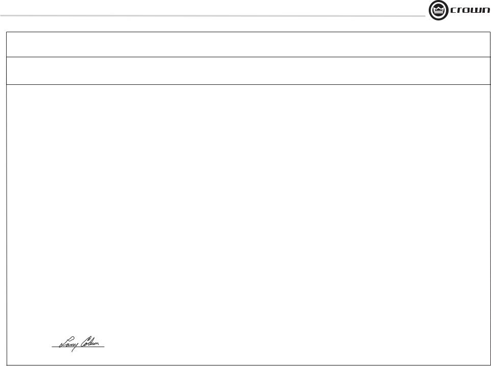
I-Tech HD Series
I-T5000 HD
PRELIMINARY
Operation Manual
I-T9000 HD
I-T12000 HD
Obtaining Other Language Versions: To obtain information in another language about the use of this product, please contact your local Crown Distributor. If you need assistance locating your local distributor, please contact Crown at 574-294-8000.
This manual does not include all of the details of design, production, or variations of the equipment. Nor does it cover every possible situation which may arise during installation, operation or maintenance.
The information provided in this manual was deemed accurate as of the publication date. However, updates to this information may have occurred. To obtain the latest version of this manual, please visit the Crown website at www.crownaudio.com.
Trademark Notice: Crown, Crown Audio, IQ, BCA, and Amcron are registered trademarks of Crown International. HiQnet is a trademark of Harman International Industries, Inc. Other trademarks are the property of their respective owners.
Some models may be exported under the name Amcron.®
©2008 by Crown Audio® Inc., 1718 W. Mishawaka Rd., Elkhart, Indiana 46517-9439 U.S.A. Telephone: 574-294-8000
140811-1 12/08
I-Tech HD Series Power Amplifiers
Important Safety Instructions |
Wichtige Sicherheitsinstruktionen |
Importantes Instructions de Sécurité |
Instrucciones de Seguridad Importantes |
The I-Tech Series amplifi ers are certifi ed only at 120V in Canada.
IMPORTANT
1.Read these instructions.
2.Keep these instructions.
3.Heed all warnings.
4.Follow all instructions.
5.Do not use this apparatus near water.
6.Clean only with a dry cloth.
7.Do not block any ventilation openings. Install in accordance with the manufacturer’s instructions.
8.Do not install near any heat sources such as radiators, heat registers, stoves, or other apparatus (including amplifi ers) that produce heat.
9.Do not defeat the safety purpose of the polarized or grounding-type plug. A polarized plug has two blades with one wider than the other. A grounding-type plug has two blades and a third grounding prong. The wide blade or the third prong is provided for your safety. If the provided plug does not fi t into your outlet, consult an electrician for replacement of the obsolete outlet.
10.Protect the power cord from being walked on or pinched, particularly at plugs, convenience receptacles, and the point where they exit from the apparatus.
11.Only use attachments/accessories specifi ed by the manufacturer.
12.Use only with a cart, stand, tripod, bracket, or table specifi ed by the manufacturer, or sold with the apparatus. When a cart is used, use caution when moving the cart/apparatus combination to avoid injury from tip-over.
13.Unplug this apparatus during lightning storms or when unused for long periods of time.
14.Refer all servicing to qualifi ed service personnel. Servicing is required when the apparatus has been damaged in any way, such as power-supply cord or plug is damaged, liquid has been spilled or objects have fallen into the apparatus, the apparatus has been exposed to rain or moisture, does not operate normally, or has been dropped.
15.Use the mains plug to disconnect the apparatus from the mains.
16.WARNING: TO REDUCE THE RISK OF FIRE OR ELECTRIC SHOCK, DO NOT EXPOSE THIS APPARATUS TO RAIN OR MOISTURE.
17.DO NOT EXPOSE THIS EQUIPMENT TO DRIPPING OR SPLASHING AND ENSURE THAT NO OBJECTS FILLED WITH LIQUIDS, SUCH AS VASES, ARE PLACED ON THE EQUIPMENT.
18.THE MAINS PLUG OF THE POWER SUPPLY CORD SHALL REMAIN READILY OPERABLE.
TO PREVENT ELECTRIC SHOCK DO NOT REMOVE TOP OR BOTTOM COVERS. NO USER SERVICEABLE PARTS INSIDE. REFER SERVICING TO QUALIFIED SERVICE PERSONNEL.
ÀPRÉVENIR LE CHOC ÉLECTRIQUE N’ENLEVEZ PAS LES COUVERCLES. IL N’Y A PAS DES PARTIES SERVICEABLE
ÀL’INTÉRIEUR. TOUS REPARATIONS DOIT ETRE FAIRE PAR PERSONNEL QUALIFIÉ SEULMENT.
PARA PREVENIR UN CHOQUE ELÉCTRICO, NO RETIRE LAS CUBIERTAS SUPERIOR O INFERIOR. NO EXISTEN PARTES QUE PUEDAN SER REPARADAS POR EL USUARIO AL INTERIOR. REMITA EL SERVICICO AL PERSONAL TÉCHNICAL CALIFICADO.
TO COMPLETELY DISCONNECT THIS EQUIPMENT FROM THE AC MAINS, DISCONNECT THE POWER SUPPLY CORD PLUG FROM THE AC RECEPTACLE. THE MAINS PLUG OF THE POWER SUPPLY CORD SHALL REMAIN READILY OPERABLE.
POUR DÉMONTER COMPLÈTEMENT L’ÉQUIPEMENT DE L’ALIMENTATION GÉNÉRALE, DÉMONTER LE CÂBLE D’ALIMENTATION DE SON RÉCEPTACLE. LA PRISE D’ALIMENTATION RESTERA AISÉMENT FONCTIONNELLE.
PARA DESCONECTAR COMPLETAMENTE EL EQUIPO DEL SUMINSTRO ELECTRICO, DESCONECTE EL CABLE DE ALIMENTACION DE LA TOMA DE CA. LAS PATAS DEL CONECTOR DEL CABLE DE ALIMENTACIÓN DEBERAN MANTENERSE EN BUEN ESTADO.
WATCH FOR THESE SYMBOLS:
The lightning bolt triangle is used to alert the user to the risk of electric shock.
The exclamation point triangle is used to alert the user to important operating or maintenance instructions.
REGARDEZ CES SYMBOLES:
La triangle avec le sigle ‘’foudre’’ est employée pour alerter l’utilisateur au risque de décharge électrique. Le triangle avec un point d’exclamation est employée pour alerter l’utilisateur d’instruction importantes pour lors opérations de maintenance.
ATENCION CON ESTOS SÍMBOLOS:
El triángulo con el símbolo de rayo eléctrico es usado para alertar al usuario de el riesgo de un choque eléctrico.
El triángulo con el signo de admiración es usado para alertar al usuario de instrucciones importantes de operación o mantenimiento.
I-Tech Series amplifi ers require Class 2 output wiring.
Les amplifi cateurs de série de I-Tech exigent des câbles de sortie de classe 2.
I-Tech-Reihe-Verstärker verlangen Klasse die 2 Produktionsverdrahtung.
Los amplifi cadores de la Serie I-Tech requieren de un cableado de salida Clase 2.
MAGNETIC FIELD
CAUTION! Do not locate sensitive high-gain equipment such as preamplifi ers directly above or below the unit. Because this amplifi er has a high power density, it has a strong magnetic fi eld which can induce hum into unshielded devices that are located nearby. The fi eld is strongest just above and below the unit.
If an equipment rack is used, we recommend locating the amplifi ers) in the bottom of the rack and the preamplifi er or other sensitive equipment at the top.
FCC COMPLIANCE NOTICE
This device complies with part 15 of the FCC rules. Operation is subject to the following two conditions: (1) This device may not cause harmful interference, and (2) this device must accept any interference received, including interference that may cause undesired operation.
CAUTION: Changes or modifi cations not expressly approved by the party responsible for complicance could void the user’s authority to operate the euqipment.
NOTE: This equipment has been tested and found to comply with the limits for a Class B digital device, pursuant to part 15 of the FCC Rules. These limits are designed to provide reasonable protection against harmful interference in a residential installation. This equipment generates, uses, and can radiate radio frequency energy and, if not installed and used in accordance with the instruction manual, may cause harmful interference to radio communications. However, there is no guarantee that interference will not occur in a particular installation. If this equipment does cause harmful interference to radio or television reception, which can be determined by turning the equipment off and on, the user is encouraged to try to correct the interference by one or more of the following measures:
•Reorient or relocate the receiving antenna.
•Increase the separation between the equipment and receiver.
•Connect the equipment into an outlet on a circuit different from that to which the receiver is connected.
•Consult the dealer or an experienced radio/TV technician for help.
page 2 |
Operation Manual |
I-Tech HD Series Power Amplifiers
Crown International, Inc. |
DECLARATION of CONFORMITY |
|
|
ISSUED BY: Crown International, Inc. |
FOR COMPLIANCE QUESTIONS ONLY: |
1718 W. Mishawaka Road |
|
Elkhart, Indiana 46517 U.S.A. |
|
European Representative’s Name and Address: |
|
David Budge |
|
10 Harvest Close |
|
Yateley GU46 6YS |
|
United Kingdom |
|
Equipment Type: Commercial Audio Power Amplifi ers
Family Name: I-Tech HD
Model Names: I-T5000HD, I-T9000HD, I-T12000HD
EMC Standards:
EN 55103-1:1997 Electromagnetic Compatibility - Product Family Standard for Audio, Video, Audio-Visual and Entertainment Lighting Control Apparatus for Professional Use, Part 1: Emissions
EN 55103-1:1997 Magnetic Field Emissions-Annex A @ 10 cm and 20 cm
EN 61000-3-2:2005 and AMD1:2008 Limits for Harmonic Current Emissions (equipment input current less than or equal to 16 A per phase)
EN 61000-3-3:2008 Limitation of Voltage Fluctuations and Flicker in Low-Voltage Supply Systems Rated Current less than or equal to16A
EN 55022:2006 Limits and Methods of Measurement of Radio Disturbance Characteristics of ITE: Radiated, Class B Limits; Conducted, Class A
EN 55103-2:1997 Electromagnetic Compatibility - Product Family Standard for Audio, Video, Audio-Visual and Entertainment Lighting Control Apparatus for Professional Use, Part 2: Immunity
EN 61000-4-2:2001 Electrostatic Discharge Immunity (Environment E2-Criteria B, 4k V Contact, 8k V Air Discharge)
EN 61000-4-3:2006 Radiated, Radio-Frequency, Electromagnetic Immunity (Environment E2, criteria A)
EN 61000-4-4:2007 Electrical Fast Transient/Burst Immunity (Criteria B)
EN 61000-4-5:2006 Surge Immunity (Criteria B)
EN 61000-4-6:2006 Immunity to Conducted Disturbances Induced by Radio-Frequency Fields (Criteria A)
EN 61000-4-11:2004 Voltage Dips, Short Interruptions and Voltage Variation
Safety Standard:
IEC 60065: 2001 7th Ed. and AMD 1: 2005 Safety Requirements - Audio Video and Similar Electronic Apparatus
I certify that the product identifi ed above conforms to the requirements of the EMC Council Directive 89/336/EEC as amended by 92/31/EEC, and the Low Voltage Directive 73/23/EES as amended by 93/68/EEC.
Signed
Title: Senior Vice President of Manufacturing
Sue Whitfi eld 574-294-8289
Date of Issue: November 1, 2008
Operation Manual |
Due to line current harmonics, we recommend that you contact your supply authority before connection. |
page 3 |

I-Tech HD Series Power Amplifiers
Table of Contents
Important Safety Instructions ............................................................ |
2 |
4.6 Digital Audio Options (AES/EBU)............................................ |
26 |
Declaration of Conformity.................................................................. |
3 |
4.7 Networking the Amplifi er......................................................... |
26 |
Table of Contents............................................................................... |
4 |
4.8 Software-Controllable Onboard DSP ..................................... |
26 |
1 Welcome ........................................................ |
5 |
5 Troubleshooting................................................. |
39 |
1.1 Features ................................................................................. |
5 |
6 Specifications ................................................... |
41 |
1.2 How to Use This Manual ......................................................... |
5 |
7 AC Power Draw and Thermal Dissipation.................... |
45 |
2 Setup ............................................................. |
6 |
8 Advanced Features ............................................. |
48 |
2.1 Unpack and Install Your Amplifi er .......................................... |
6 |
8.1 Protection Systems ................................................................ |
48 |
2.2 Connecting to AC Mains ........................................................ |
7 |
8.2 Global, Switching Power Supply with PFC ............................. |
48 |
2.3 Wire Inputs and Outputs ......................................................... |
7 |
8.3 3rd Generation Class I Circuitry .............................................. |
48 |
3 Operation ........................................................ |
11 |
8.4. Color-Coded Rear Overlay .................................................... |
498 |
3.1 Protecting Your Speakers........................................................ |
11 |
9 Appendix A: Network and CobraNet Basics.................. |
49 |
3.2 Startup Procedure .................................................................. |
11 |
Appendix B: Setting Sensitivity for Best Gain Staging...... |
53 |
3.3 Precautions ............................................................................ |
11 |
10 Service.......................................................... |
54 |
3.4 Front Panel Controls and Indicators ....................................... |
12 |
11 Warranty........................................................ |
55 |
3.5 Back Panel Controls, Indicators and Connectors .................... |
13 |
Product Registration.......................................................................... |
57 |
4 Advanced Operation ............................................ |
14 |
Crown Factory Service Information Form .......................................... |
59 |
4.1 Advanced Operation Table of Contents .................................... |
14 |
|
|
4.2 Navigating the LCD Control Screen......................................... |
15 |
|
|
4.3 Presets ................................................................................... |
23 |
|
|
4.4 File Transfer Via the USB Port.................................................. |
24 |
|
|
4.5 List of Pop-Up Boxes and Descriptions................................... |
25 |
|
|
page 4 |
Operation Manual |
I-Tech HD Series Power Amplifiers
I-T5000HD |
20 Hz - 20 kHz |
Power |
|
2-ohm Dual (per ch.) |
1,800W |
4-ohm Dual (per ch.) |
2,000W |
8-ohm Dual (per ch.) |
1,250W |
4-ohm Bridge |
3,600W |
8-ohm Bridge |
4,000W |
20 Hz - 20 kHz Power refers to guaranteed minimum power in watts with 0.35% THD.
I-T9000HD |
20 Hz - 20 kHz |
Power |
|
2-ohm Dual (per ch.) |
2,500W |
4-ohm Dual (per ch.) |
3,000W |
8-ohm Dual (per ch.) |
1,500W |
4-ohm Bridge |
5,000W |
8-ohm Bridge |
6,000W |
20 Hz - 20 kHz Power refers to guaranteed minimum power in watts with 0.35% THD.
I-T12000HD |
20 Hz - 20 kHz |
Power |
|
2-ohm Dual (per ch.) |
3,500W |
4-ohm Dual (per ch.) |
4,000W |
8-ohm Dual (per ch.) |
2,100W |
4-ohm Bridge |
7,000W |
8-ohm Bridge |
8,000W |
20 Hz - 20 kHz Power refers to guaranteed minimum power in watts with 0.35% THD.
1 Welcome
The Crown® I-Tech HD Series offers amazing power, light weight and ease of use for touring sound applications. Unlike other amplifi ers, it includes onboard high-defi nition DSP, an LCD control screen, and a built-in network connection.
Modern power amplifi ers are sophisticated pieces of engineering capable of producing extremely high power levels. They must be treated with respect and correctly installed if they are to provide the many years of reliable service for which they were designed.
In addition, I-Tech Series amplifi ers include a number of features which require some explanation before they can be used to their maximum advantage.
Please take the time to study this manual so that you can obtain the best possible service from your amplifi er.
1.1 Features
•Global Power Supply with PFC (Power Factor Correction) works anywhere in the world.
•High power density, up to 8000 watts in a 2U chassis.
•Highest output voltage in the industry (200V peak) provides clean transient peaks.
•3rd-generation patented Class I (BCA®) circuitry couples power effi ciently to the load and provides low AC current draw.
•Onboard high-defi nition DSP with 24-bit, 192 kHz Cirrus Logic SHARC A/D and D/A converters. Advanced IIR fi lters and linearphase FIR fi lters.
•Pushbutton presets simplify setup. Custom presets for various loudspeakers can be downloaded.
•AES/EBU digital audio input.
•EtherCon® Ethernet connector for HiQnet™ control or CobraNet digital audio transport. This “Single Plug” connection allows HiQnet protocol and CobraNet digital audio through the same CAT 5 cable.
•Analog and digital thru connectors.
•LCD Control Screen is used to adjust the amplifi er’s attenuation and muting, confi gure the amp, set up and view error monitoring, and recall DSP presets to reconfi gure the amp for various applications.
•Comprehensive array of indicators provide accurate diagnostics: Power, Data, along with Ready, Signal, Clip, Thermal and Fault for each channel.
•AC mains indicator in power switch glows green when AC power is present.
•Front-panel USB connector accepts a USB drive to transfer presets from the drive to the amplifi er DSP, and vice versa.
•Light weight due to aluminum chassis, special internal construction and switching power supply.
•Thermal management controller and two discrete thermal zones with variable-speed fans, forced-air cooling.
•Advanced protection circuitry guards against: shorted outputs, DC, mismatched loads, general overheating, under/over voltage, highfrequency overloads and internal faults.
•Three-Year, No-Fault, Fully Transferable Warranty completely protects your investment and guarantees its specifi cations.
1.2 How to Use This Manual
This manual provides you with the necessary information to safely and correctly setup and operate your amplifi er. It does not cover every aspect of installation, setup or operation that might occur under every condition. For additional information, please consult the online help in System Architect software, Crown’s Amplifier Application Guide, I-Tech Application Guide (available online at www. crownaudio.com), Crown Technical Support, your system installer or retailer.
We strongly recommend you read all instructions, warnings and cautions contained in this manual. Also, for your protection, please send in your warranty registration card today. And save your bill of sale — it’s your offi cial proof of purchase.
Operation Manual |
page 5 |
I-Tech HD Series Power Amplifiers
2 Setup
2.1 Unpack and Install Your Amplifier
Please unpack and inspect your amplifi er for any damage that may have occurred during transit. If damage is found, notify the transportation company immediately. Only you can initiate a claim for shipping damage. Crown will be happy to help as needed. Save the shipping carton as evidence of damage for the shipper’s inspection.
We also recommend that you save all packing materials so you will have them if you ever need to transport the unit. Never ship the unit without the factory pack.
YOU WILL NEED (not supplied):
• Input wiring cables
• Output wiring cables
• Ethernet cables
• Rack for mounting amplifi er (or a stable surface for stacking)
WARNING: Before you start to set up your amplifier, make sure you read and observe the Important Safety Instructions found at the beginning of this manual.
CAUTION: Before you begin, make sure your amplifier is disconnected from the power source, with the power switch in the “off” position and all level controls turned completely down (counterclockwise).
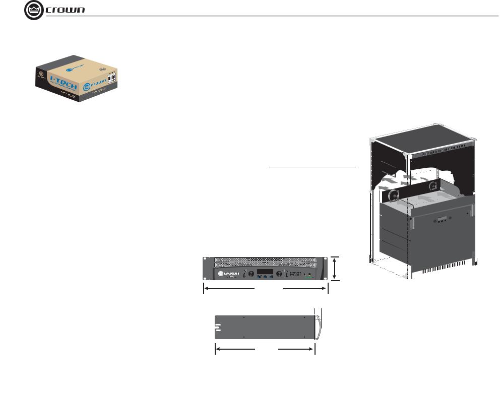
Use a standard 19-inch (48.3 cm) equipment rack (EIA RS-310B). See Figure 2.1 for amplifi er dimensions.
You may also stack amps without using a cabinet.
NOTE: When transporting, amplifi ers should be supported at both front and back.
MAGNETIC FIELD
CAUTION! Do not locate sensitive high-gain equipment such as preamplifi ers or tape decks directly above or below the unit. Because this amplifi er has a high power density, it has a strong magnetic fi eld which can induce hum into unshielded devices that are located nearby. The fi eld is strongest on the right side and right bottom of the amplifi er (facing the amplifi er).
If an equipment rack is used, we recommend locating sensitive equipment at least 20 cm (8 inches) away from the amplifi er.
3.5 In.
8.9 cm
19 In.
48.3 cm
1.5 In.
3.8 cm
When using an equipment rack, mount units directly on top of each other. Close any open spaces in rack with blank panels. DO NOT block front or rear air vents. The side walls of the rack should be a minimum of two inches (5.1 cm) away from the amplifi er sides, and the back of the rack should be a minimum of four inches (10.2 cm) from the amplifi er back panel.
Figure 2.2 illustrates standard amplifi er airfl ow.
Figure 2.2 Airflow
16.2In.
41.1cm
|
Figure 2.1 |
page 6 |
Dimensions |
Operation Manual
I-Tech HD Series Power Amplifiers
2 Setup
2.2 Connecting to AC Mains
WARNING: The third (ground) prong of the supplied AC power cord connector is a required safety feature. Do not attempt to disable this ground connection by using an adapter or other methods.
Amplifi ers don’t create energy. The AC mains voltage and current must be suffi cient to deliver the power you expect. You must operate your amplifi er from an AC mains power source with not more than a 10% variation above or a 15% variation below the amplifi er’s specifi ed line voltage range and within the specifi ed frequency requirements (indicated on the amplifi er’s back panel label). If you are unsure of the output voltage of your AC mains, please consult your electrician.
Packed with your I-Tech amplifi er is a clip that retains the power cord so it can’t pull out accidentally.
1.Locate the clip in a bag in the I-Tech packing carton.
2.Locate the IEC power connector on the back of the amplifi er. Above and below that connector are two slots. Stretch the ends of the clip and insert them into the slots (Figure 2.3).
3.Plug the power cord all the way into the amplifi er IEC power connector.
4.Pull the clip to the left and snap it onto the power cord.
Slot
|
|
|
|
|
Clip |
|
|
|
|
|
|
|
|
|
|
|
|
|
|
|
|
|
|
|
|
|
|
|
|
|
|
|
|
|
|
|
|
|
|
|
|
|
|
|
|
|
|
|
Slot |
||||
|
|
||||
IEC Power Connector |
|
||||
Figure 2.3 IEC Power Connector Clip
2.3 Wire Inputs and Outputs
2.3.1 Wiring basics
•Always use shielded wire for input wiring. The higher the density of the shield (the outer conductor) the better. Spiral wrapped shield is not recommended.
•When using unbalanced lines keep the cables as short as possible. Avoid lengths greater than 10 feet (3 meters).
•Do not run the audio input cables together with the high-level wiring such as loudspeaker wires or AC cords. (This lessens the chance of hum and noise being induced into the input cables.)
•Turn the entire sound system off before changing any connections. Crown is not liable for damage incurred when any transducer or component is overdriven.
THE CHANNEL 2 INPUT IS IGNORED by default in Bridge Mono mode. It can be summed using the input source selector and used instead of Channel 1. 
For additional information on audio input wiring please refer to the Crown Amplifier Application Guide available online at www.crownaudio.com. It contains helpful information on preventing unwanted subsonic frequencies, radio frequency interference, ground loops, and feedback oscillation.
When using network connections, pass the CAT 5 cable fi ve times through a ferrite core (Figure 2.4), available from Crown Audio Inc. This is to ensure compliance with emission regulations.
Figure 2.4 Pass the CAT 5 Cable Five Times Through the Ferrite Core
Operation Manual |
page 7 |
I-Tech HD Series Power Amplifiers
2Setup
2.3.2Choose Input Wire and Connectors
Crown recommends using pre-built or professionally wired, balanced line (two-conductor plus shield), 22-24 gauge cables and connectors. Use 3-pin male XLR connectors.
Unbalanced line may also be used but may result in noise over long cable runs.
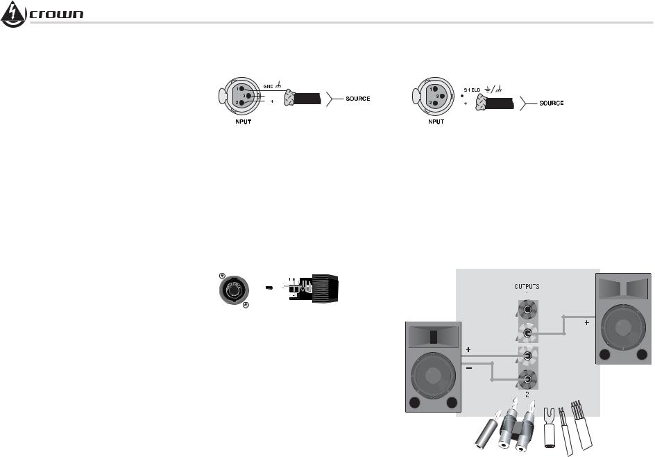
Figure 2.5 shows connector pin assignments for balanced analog wiring or AES/EBU digital wiring. The use of standard analog cable with AES/EBU will result in diminished performance. For best results, 110 ohm shielded twisted-pair cable for AES/EBU signals is highly recommended. Figure 2.6 shows connector pin assignments for unbalanced analog wiring.
NOTE: Custom wiring should only be performed by qualifi ed personnel.
2.3.3 Choose Output Wire and Connectors
Crown recommends using pre-built or professionally wired, highquality, twoor four-conductor, heavy gauge speaker wire and connectors. Use Class 2 output wiring. You may use a 4-pole Speakon® connector (Figure 2.7) or banana plugs, spade lugs, or bare wire for your output connectors (Figure 2.8). To prevent the possibility of short circuits, wrap or otherwise insulate exposed loudspeaker cable connectors.
CAUTION – SHOCK HAZARD: Potentially lethal voltages exist at the output connectors when the amplifier is turned on and is passing a signal.
Using the guidelines below, select the appropriate size of wire based on the distance from amplifi er to speaker.
Distance |
Wire Size |
up to 25 ft. |
16 AWG |
26-40 ft. |
14 AWG |
41-60 ft. |
12 AWG |
61-100 ft. |
10 AWG |
101-150 ft. |
8 AWG |
151-250 ft. |
6 AWG |
CAUTION: Never use shielded cable for output wiring.
|
|
|
|
|
|
|
|
|
|
|
|
|
|
|
|
|
|
|
|
|
|
|
|
|
|
|
|
|
|
|
|
|
|
|
|
|
|
|
|
|
|
|
|
|
|
|
|
|
|
|
|
|
|
|
|
|
|
|
|
|
|
|
|
|
|
|
|
|
|
|
|
|
|
|
|
|
|
|
|
|
|
|
|
|
|
|
|
|
|
|
|
|
|
|
|
|
|
|
|
|
|
|
|
|
|
|
|
|
|
|
|
|
|
|
|
|
|
|
|
|
|
|
|
Figure 2.5 |
Figure 2.6 Unbalanced Analog Input Connector Wiring |
|
|
|
|
|
|
|||||||||||||||||||||||
Balanced Analog Input Connector Wiring or |
|
|
|
|
|
|
||||||||||||||||||||||||
|
|
|
|
|
|
|
|
|
|
|
|
|
|
|
|
|
|
|
||||||||||||
AES/EBU Digital Connector Wiring |
|
|
|
|
|
|
|
|
|
|
|
|
|
|
|
|
|
|
|
|||||||||||
|
|
|
|
|
|
|
|
|
|
|
|
|
|
|
|
|
|
|
|
|
|
|
|
|
|
|
|
|
|
|
|
|
|
|
|
|
|
|
|
|
|
|
|
|
|
|
|
|
|
|
|
|
|
|
|
|
|
|
|
|
|
|
|
|
|
|
|
|
|
|
|
|
|
|
|
|
|
|
|
|
|
|
|
|
|
|
|
|
|
|
|
|
|
|
|
|
|
|
|
|
|
|
|
|
|
|
|
|
|
|
|
|
|
|
|
|
|
|
|
|
|
|
|
|
|
|
|
|
|
|
|
|
|
|
|
|
|
|
|
|
|
|
|
|
|
|
|
|
|
|
|
|
|
|
|
|
|
|
|
|
|
|
|
|
|
|
|
|
|
|
|
|
|
|
|
|
|
|
|
|
|
|
|
|
|
|
|
|
|
|
|
|
|
|
|
|
|
|
|
|
|
|
|
|
|
|
|
|
|
|
|
|
|
|
|
|
|
|
|
|
|
|
|
|
|
|
|
|
|
|
|
|
|
|
|
|
|
|
|
|
|
|
|
|
|
|
|
|
|
|
|
|
|
|
|
|
|
|
|
|
|
|
|
|
|
|
|
|
|
|
|
|
|
|
|
|
|
|
|
|
|
|
|
|
|
|
|
|
|
|
|
|
|
|
|
|
|
|
|
|
|
|
|
|
|
|
|
|
|
|
|
|
|
|
|
|
|
|
|
|
|
|
|
|
|
|
|
|
|
|
|
|
|
|
|
|
|
|
|
|
|
|
|
|
|
|
|
|
|
|
|
|
|
|
|
|
|
|
|
|
|
|
|
|
|
|
|
|
|
|
|
|
|
|
|
|
|
|
|
|
|
|
|
|
|
|
|
|
|
|
|
|
|
|
|
|
|
|
|
|
|
|
Figure 2.7
Left: Speakon® Output Connector on Back Panel
Right: Speakon® Cable Connector
Figure 2.8
Binding Post Connections
page 8 |
Operation Manual |
I-Tech HD Series Power Amplifiers
2 Setup
2.3.4 Stereo Mode Wiring
Typical input and output wiring is shown in Figure 2.9.
IMPORTANT: Turn off the amplifier and unplug its power cord.
INPUTS: Choose one of these options:
•Connect analog input wiring for both channels.
•Connect an AES/EBU digital signal to the AES/EBU connector.
OUTPUTS: Maintain proper polarity (+/–) on output connectors. Use Class 2 output wiring.
Figure 2.9 shows how to wire stereo speakers to the binding posts. Connect Channel 1 loudspeaker’s positive (+) lead to Channel 1 positive (red) terminal of amp; repeat for negative (–). Repeat Channel 2 wiring as for Channel 1.
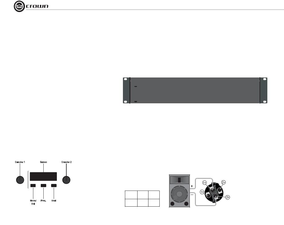
To wire stereo speakers to the Speakon® connectors, use one of these methods:
Method 1 (Table 1 and Figure 2.10): Wire one Speakon® cable connector to two speakers. Insert the Speakon® cable connector into the amplifi er’s top Speakon® connector.
Method 2 (Table 2 and Figure 2.11): Plug the Channel 1 speaker into the Channel 1 (top) Speakon® connector, and plug the Channel 2 speaker into the Channel 2 (bottom) Speakon® connector.
Table 1
Stereo Wiring Method 1: Use Top Speakon® Only
|
|
PIN |
1+ |
1– |
2+ |
|
|
2– |
|
|
|
|||||||
|
|
|
|
|
|
|
|
|
|
|
|
|
|
|
|
|
|
|
|
|
CH |
1+ |
1– |
2+ |
|
|
2– |
|
|
|
|||||||
|
|
|
|
|
|
|
|
|
|
|
|
|
|
|
|
|
|
|
|
|
|
|
|
|
|
|
|
|
|
|
|
|
|
||||
Channel 1 |
|
|
|
|
|
|
|
|
|
|
|
|
|
|
Channel 2 |
|||
Loudspeaker |
|
|
|
|
|
|
|
|
|
|
|
|
|
|
|
|
|
Loudspeaker |
Enceinte du |
|
|
|
|
|
|
|
|
|
|
|
|
|
|
|
|
|
Enceinte du |
Canal 1 |
|
|
|
|
|
|
|
|
|
|
|
|
|
|
|
|
|
Canal 2 |
|
|
|
|
|
|
|
|
|
|
|
|
|
|
|
|
|
||
Lautsprecher |
|
|
|
|
|
|
|
|
|
|
|
|
|
|
|
|
|
Lautsprecher |
Kanal 1 |
|
|
|
|
|
|
|
|
|
|
|
|
|
|
|
|
|
Kanal 2 |
Altoparlante |
|
|
|
|
|
|
|
|
|
|
|
|
|
|
|
|
|
Altoparlante |
del Canal 1 |
|
|
|
|
|
|
|
|
|
|
|
|
|
|
del Canal 2 |
|||
|
|
|
|
|
|
|
|
|
|
|
|
|
|
|
|
|
|
|
Figure 2.10 Wiring Two Stereo Speakers to the Top Speakon® Connector
Figure 2.9
System Wiring,
Stereo Mode
|
Table 2 |
|
|
Stereo Wiring Method 2: Use Both Speakon®s |
Top Speakon |
||
|
|
|
(Channel 1) |
PIN |
1+ |
1– |
|
Top |
|
|
|
CH |
1+ |
1– |
Channel 1 |
|
|
|
Loudspeaker |
PIN |
1+ |
1– |
|
Bottom |
|
|
Bottom |
CH |
2+ |
2– |
Speakon |
|
|
|
(Channel 2) |
|
|
|
Channel 2 |
|
|
|
Loudspeaker |
Figure 2.11
Stereo Wiring
Using Both
Speakon®
Connectors
Operation Manual |
page 9 |
I-Tech HD Series Power Amplifiers
2Setup
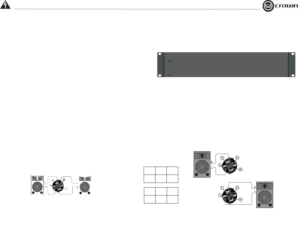
2.3.5Bridge-Mono Mode
Overview: Turn on the amp, enable Bridge-Mono mode using the LCD Control Screen, turn off the amp, wire it, and turn it back on.
1. Be sure that no cables are connected to the amplifi er. Turn on the front-panel power switch. The LCD Control Screen will light up (Figure 2.12).
2. Under the LCD Control Screen, press the Menu/Exit button. Press the Next button until you see OUTPUT MODE on the screen. If N/A is displayed, OUTPUT MODE is locked via software. If LOCKOUT is displayed, all the LCD screens are locked via software.
3.Press an Encoder knob to select BRIDGE MONO. Press the knob again to confi rm your choice. Press Menu/Exit. Turn down both level controls (Encoders) until reach maximum attenuation.
4.IMPORTANT: Turn off the amplifier and unplug its power cord.
INPUTS: There are three ways to connect an input signal to the amplifi er (Figure 2.13):
•Connect an analog signal source to the Channel-1 amplifi er input.
•Connect an AES/EBU digital signal source to the Digital Input IN connector.
NOTE: Crown provides a reference of wiring pin assignments for commonly used connector types in the Crown Amplifier Application Guide available at www.crownaudio.com.
OUTPUTS: Use Class 2 output wiring. There are two ways to wire the amplifi er output connectors for Bridge-Mono mode:
1)Wire the speaker across the red binding post of each channel (Figure 2.14). Do not use the black binding posts when operating in Bridge-Mono mode.
2)Wire the speaker only to the top Speakon® connector as shown in Table 3 and Figure 2.14.
Figure 2.12
The LCD Control Screen
|
|
|
|
|
|
|
NOTE: In Bridge-Mono |
|
|
|
|
|
|
|
mode, the Channel 1 |
|
|
|
|
|
|
|
Level control sets the |
Menu/Exit |
Prev |
Next |
level; the Channel 2 Level |
||||
|
|
|
|
|
|
|
control is defeated. All |
|
|
|
|
|
|
|
|
|
|
|
|
|
|
|
Channel-2 objects and |
|
|
|
|
|
|
|
controls are hidden and |
|
|
|
|
|
|
|
disabled. |
Figure 2.13 Bridge-Mono Wiring to Binding Posts
|
Table 3 |
|
|
Top Speakon® Wiring for Bridge-Mono |
Figure 2.14 |
||
|
|
|
Wiring a Speaker in Bridge-Mono Mode to |
PIN |
1+ |
2+ |
the Top Speakon® Connector |
|
|||
SPKR |
+ |
– |
|
page 10 |
Operation Manual |
I-Tech HD Series Power Amplifiers
3Operation
3.1Protecting Your Speakers
It’s wise to avoid clipping the amplifi er signal. Not only does clipping sound bad, it can damage high-frequency drivers. To prevent clipping, use System Architect software’s Level Max suite to enable or display the peak voltage limiter and average power limiter in your amplifi er’s built-in DSP. That way, no matter how strong a signal your mixer produces, the amplifi er output will not clip. Set the limiter threshold so that mixer signals above 0 dB or 0 VU on the mixer meters do not quite drive the amplifi er into clipping.
Also, avoid sending strong subsonic signals to the amplifi er. Highlevel, low-frequency signals from breath pops or dropped microphones can blow out drivers. To prevent subsonic signals, use one of these methods:
•Insert a highpass fi lter between mixer output and amplifi er input (or between mixer and limiter).
•Use the I-Tech’s onboard DSP to set up a highpass fi lters.
•Switch in highpass fi lters at your mixer. Set the fi lter to as high a frequency as possible that does not affect your program. For example, try 35 Hz for music and 75 Hz for speech. On each mixer input channel, set the fi lter frequency just below the lowest fundamental frequency of that channel’s instrument.
3.2 Startup Procedure
When fi rst turning on your amplifi er, follow the procedures in the Quick-Start Guide on page 4 (stereo) or page 5 (bridge-mono).
If you ever need to make any wiring or installation changes, don’t forget to disconnect the power cord.
For help with determining your system’s optimum gain structure (signal levels) please refer to the Crown Amplifier Application Guide, available online at www.crownaudio.com.
3.3 Precautions
Your amplifi er is protected from internal and external faults, but you should still take the following precautions for optimum performance and safety:
1.Before use, your amplifi er fi rst must be confi gured for proper operation, including input and output wiring hookup. Improper wiring can result in serious operating diffi culties. For information on wiring and confi guration, please consult the Setup section of this manual or, for advanced setup techniques, consult Crown’s
Amplifier Application Guide available online at www.crownaudio.com.
2.Use care when making connections, selecting signal sources and controlling the output level. The load you save may be your own!
3.Do not short the ground lead of an output cable to the input signal ground. This may form a ground loop and cause oscillations.
4.WARNING: Never connect the output to a power supply, battery or power main. Electrical shock may result.
5.Tampering with the circuitry, or making unauthorized circuit changes may be hazardous and invalidates all agency listings.
6.Do not operate the amplifi er with the red Clip LEDs constantly fl ashing.
7.Do not overdrive the mixer, which will cause clipped signal to be sent to the amplifi er. Such signals will be reproduced with extreme accuracy, and loudspeaker damage may result.
8.Do not operate the amplifi er with less than the rated load impedance. Due to the amplifi er’s output protection, such a confi guration may result in premature clipping and speaker damage.
9.CAUTION – SHOCK HAZARD: Potentially lethal voltages exist at the output connectors when the amplifier is turned on and is passing a signal.
Remember: Crown is not liable for damage that results from overdriving other system components.
Operation Manual |
page 11 |
I-Tech HD Series Power Amplifiers
3Operation
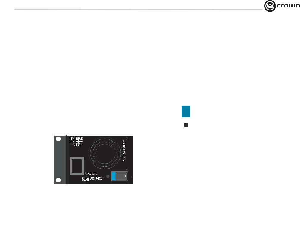
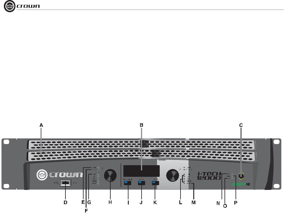
3.4Front Panel Controls and Indicators
Many of these functions can be disabled using Blackout Mode (a selection in the Advanced Menu, Section 4.2.3).
A. Cooling Vents
Front-to-rear forced airfl ow through foam dust fi lter
B. LCD Control Screen
Integrated LCD with white backlight, controls amplifi er setup and operation.
The LCD Control Screen and its controls let the user adjust the amplifi er’s attenuation and muting,
confi gure the amp, set up and view error monitoring (such as temperature and load supervision), and recall DSP presets. The presets allow the user to quickly reconfi gure the amp for various applications.
C.Power Switch
Push-on/push-off switch glows green when AC power is present at the power cord and the amplifi er circuit breaker is in the “on” position.
D.USB 2.0 Connector
Accepts a USB drive to transfer presets from the drive to the amplifi er DSP, and vice versa.
E.Fault Indicator
Red LED, one per channel, fl ashes when the amplifi er output channel has stopped operating. Usually this means that the amplifi er must be serviced.
F.Thermal Indicator
Red LED, one per channel, illuminates when the channel has shut down due to thermal stress or overload.
G.Clip Indicator
Red LED, one per channel, illuminates when the channel’s output signal reaches the onset of audible clipping. The Clip Indicator also will illuminate during Thermal Level Control (TLC) limiting. The Clip Indicator can be turned of during Blackout mode.
H. Level Controls (Encoders)
Speed-sensitive, 0.5 dB steps, range 0 to –100 dB. These two knobs affect the Channel-1 and Channel-2 output levels. They also select Menu items and adjust parameter values that are displayed on the LCD control screen.
I. Menu/Exit Button
“Menu” enters the main menu. “Exit” leaves the menu.
J. Prev Button
Selects the previous item in the menu.
K. Next Button
Selects the next item in the menu.
L. Signal Indicators
These can be disabled during Blackout mode. Three green LEDS per channel indicate the amplifi er’s input and output signal levels. From top to bottom the LEDs are
–10 dB: amplifi er output is 10 dB below clipping. –20 dB: amplifi er output is 20 dB below clipping. Signal: selected input signal is above –40 dBu.
M. Ready Indicator
Green LED, one per channel, illuminates when the channel is initialized and ready to produce audio output. Indicator is off when the channel is set to standby mode via System Architect or in Blackout mode.
N.Power Indicator
Blue LED indicates amplifi er has been turned on and AC power is available. The LED will fl ash when the AC line voltage is 15% above or below the nominal rated range. This indicator can be turned off in Blackout mode.
O.Data Indicator
Yellow LED indicates network data activity. Data indicator fl ashes only when the amplifi er is polled for data, or is polled to see whether it is online. This indicator can be turned off in Blackout mode.
PBridge Mode Indicator
Yellow LED illuminates when the amplifi er is set to Bridge-Mono mode.
Figure 3.1 Front Panel Controls and Indicators
page 12 |
Operation Manual |

I-Tech HD Series Power Amplifiers
3 Operation
3.5 Back Panel Controls, Indicators
and Connectors
A. Fans
Provide front-to-back forced airfl ow for cooling.
ANALOG INPUTS SECTION
B. Balanced Analog XLR Inputs
A 3-pin female XLR connector for each channel.
C. Balanced Analog XLR Loop-Through Outputs
Two 3-pin male XLR output connectors are provided (one per channel). The signal at these connectors is paralleled with the input signal for feeding the input signal to other amplifi ers.
OUTPUTS SECTION
D. 4-Pole Speakon® Output Connectors
Two high-current, 50A Neutrik® Speakon® NL4MLP (mates with NL4FC and NL4), one per channel. Class 2 output wiring required.
These two connectors accept 2-pole or 4-pole Speakon® connectors. See Figures 2.5 through 2.10 and Tables 1, 2 and 3 for connector wiring. The top Speakon® connector is wired for both channels so it can be used for bridge-mono wiring or for stereo wiring of two speakers to a single Speakon® connector.
E. Binding Post Output Jacks
One pair per channel of high-current, 60A colorcoded binding posts. Accepts banana plugs, wire or spade lugs.
F. Power Cord Connector
Standard 20 amp IEC inlet. Voltage range is indicated above IEC inlet.
G. Reset Switch/Circuit Breaker
If the current draw of the amplifi er exceeds safe limits, this breaker automatically disconnects the power supply from the AC mains. The switch resets the circuit breaker.
H. MAC Address
This specifi c amplifi er’s network identifi er that is burned into its fi rmware.
I. Preset Indicator
LED fl ashes to signal the number of the current preset if active. LED is green if the preset values have not been changed once loaded. LED is yellow if the preset values have been changed since they were loaded.
J. Reset Button
To restore factory default settings: Press the Reset Button with a thin, non-conductive object, then turn on amplifi er power, and continue to hold the reset button until the Preset light comes on green (approximately 16 seconds)..
K. Data Indicator
Flashes yellow only when the amplifi er is polled for data, or is polled to see whether it is online.
DIGITAL INPUTS SECTION
L. AES/EBU Digital Input
This 3-pin female XLR connector accepts a digital signal in the AES/EBU format.
M AES/EBU Digital Loop-through Output
Male XLR active/re-clocked AES/EBU digital loop-through. The signal at this connector duplicates the digital input signal for feeding the input signal to other amplifi ers.
It is not recommended to loop through more than four amplifi ers. If larger distribution of AES is needed, the use of an AES distribution amplifi er is recommended.
NETWORKING SECTION
N. Link/Act Indicator
Shows network activity.The LINK ACT LED illuminates when the network port is connected and fl ashes when network activity is detected.
O. Network Connector
This EtherCon® Ethernet connector is for networking. Warning: Only connect to networks that remain inside the building.
P. Cond Indicator
Turns on if the amplifi er is set to be the CobraNet conductor. The CobraNet conductor is a CobraNet node that provides the master timing clock for the CobraNet digital audio transport network.
Figure 3.2 Back Panel Controls and Connectors
Operation Manual |
page 13 |

I-Tech HD Series Power Amplifiers
4 Advanced Operation
4.1 Advanced Operation Table of Contents....... |
14 |
|
|
4.2 Navigating the LCD Control Screen ................... |
15 |
4.8.3 Levels and Indicators ..................................................... |
27 |
4.2.1 Introduction ................................................................... |
15 |
4.8.4 Input Signal Router ........................................................ |
28 |
4.2.2 Basic Selections ............................................................ |
16 |
4.8.5 Source Confi guration .................................................... |
29 |
4.2.3 Advanced Menu............................................................. |
17 |
4.8.6 CobraNet Advanced Settings ......................................... |
29 |
4.2.4 Monitor Menu ............................................................... |
20 |
4.8.7 Input Signal Compressor .............................................. |
30 |
4.2.5 Alert Menu..................................................................... |
20 |
4.8.8 Input Delay and Driver Delay.......................................... |
30 |
4.2.6 Networking Menu .......................................................... |
21 |
4.8.9 Input EQ and Output EQ ................................................. |
31 |
4.2.7 CobraNet Menu ............................................................. |
22 |
4.8.10 Crossover Filters ......................................................... |
32 |
4.3 Presets.................................................... |
23 |
4.8.11 LevelMax Suite ........................................................... |
33 |
4.3.1 Introduction................................................................... |
23 |
4.8.12 Front Panel Security .................................................... |
33 |
4.3.2 User Presets .................................................................. |
23 |
4.8.13 Amplifi er Settings ....................................................... |
34 |
4.3.3 Downloadable Presets ................................................... |
23 |
4.8.14 Amplifi er Information .................................................. |
35 |
4.4 File Transfer Via the USB Port ......................... |
24 |
4.8.15 Apply to Others ........................................................... |
35 |
4.5 List of Pop-Up Boxes and Descriptions ............... |
25 |
4.8.16 Delay (Latency) ........................................................... |
35 |
4.6 Digital Audio Options (AES/EBU) ...................... |
26 |
4.8.17 Preset Manager ........................................................... |
36 |
4.7 Networking the Amplifier ............................... |
26 |
4.8.18 Signal Generator.......................................................... |
37 |
4.7.1 NetworkTroubleshooter................................................... |
26 |
4.8.19 Fixed-Gain Mode in the I-Tech HD ............................... |
38 |
4.8 Software-Controllable Onboard DSP ................. |
26 |
|
|
4.8.1 Amplifi er DSP Selection Screen ..................................... |
27 |
|
|
4.8.2 Amplifi er Mode ............................................................. |
27 |
|
|
page 14 |
Operation Manual |
I-Tech HD Series Power Amplifiers |
|
4 Advanced Operation |
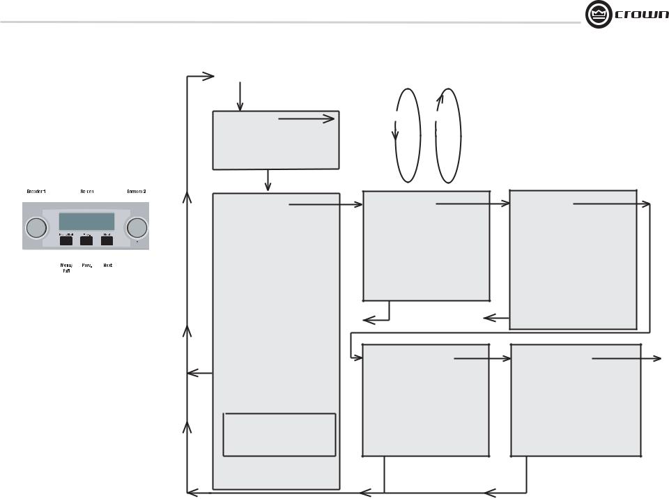
MENU TREE |
4.2 Navigating the LCD Control Screen
4.2.1 Introduction
The LCD Control Screen and its controls let you confi gure the amplifi er and access many features that before were available only through a remote computer. Also, you can recall DSP presets via the front panel. (Some DSP parameters cannot be adjusted with the LCD Control Screen. That is done in System Architect.)
Figure 4.1 shows the parts of the LCD Control Screen. Its functions are described below. NOTE: Listed functions can also be controlled in System Architect.
Attenuation - Mute - Lockout
Menu button
Sample Rate
Analog Input Sensitivity
Presets
Amp Mode
Locate
Next
ALL MENUS: Next/Previous loops
Prev to |
Next |
Prev |
Cobranet |
|
|
Menu |
|
|
Menu Tree
As a handy reference, Figure 4.2 shows the menu structure of the LCD control screen. Starting from any Menu screen, press an Encoder knob to go to the fi rst selection in the Menu. You can loop through a menu’s selections using the Next and Prev buttons. The Menu/Exit button returns you to the Attenuation screen which you see on power-up.
|
|
|
|
|
|
|
|
|
|
|
|
|
Next |
|
|
|
|
|
|
|
|
|
|
|
|
|
|
ADVANCED MENU |
|
|
|
|
|
|
|
|
|
|
|
|
|
|
(press knob once to access these |
|
|
|
|
|
|
|
|
|
|
|
|
|
|
items:) |
|
|
|
|
|
|
|
|
|
|
|
|
|
|
|
|
|
|
|
|
|
|
|
|
|
|
|
|
|
Attenuator Limits |
|
|
|
|
|
|
|
|
|
|
|
|
|
|
Attenuator Link |
|
|
|
|
|
|
|
|
|
|
|
|
|
|
Input Sources |
|
|
|
|
|
|
|
|
|
|
|
|
|
|
Analog Source Select |
|
Figure 4.1 Parts of the LCD Control Screen |
|
Maximum Analog Input |
|
|||||||||||
Here’s how to access the various menus and settings in the LCD |
|
Digital Source Select |
|
|||||||||||
control screen: |
|
AES Source Select |
|
|||||||||||
• Starting from the Attenuation screen, press Menu/Exit to go to |
|
AES Input Trim |
|
|||||||||||
|
AES Input Status |
|
||||||||||||
the Sample Rate screen. |
|
Cobranet Source Select |
|
|||||||||||
• Press Next to go to the next item in the menu. |
|
|
||||||||||||
|
Cobranet Input Trim |
|
||||||||||||
• Press Prev to go to the previous item in the menu. |
|
|
||||||||||||
|
Bandpass Gain |
|
||||||||||||
• Turn or press either Encoder knob to change the value of the |
Exit |
|
||||||||||||
displayed parameter. |
Output Polarity |
|
||||||||||||
• When you see a menu screen, push the knob once to see the |
|
Input Delay |
|
|||||||||||
items in that menu. Or press Next to go to the next menu. |
|
Speaker Delay |
|
|||||||||||
• Press Menu/Exit to leave the menu and return to the Attenuation |
|
LED Meter Display Type |
|
|||||||||||
screen at any time. |
|
Bar Meter Display Type |
|
|||||||||||
Some menu items require confi rmation: after you request a change, |
|
|
||||||||||||
|
LevelMax |
|
||||||||||||
the display might say “Press and hold.” To confi rm a change, press |
|
Level |
||||||||||||
|
Peak Voltage Limiter |
|||||||||||||
and hold an Encoder knob. If you don’t want the change to occur |
|
|||||||||||||
|
Max |
|||||||||||||
during a confi rmation, turn the knob or wait fi ve seconds. |
|
RMS Voltage Limiter |
Suite |
|||||||||||
The entire front panel or just selected screens can be locked out or |
|
Transducer Thermal Limiter |
|
|||||||||||
|
Pink Noise Generator |
|
||||||||||||
set to read only status using System Architect software. Locked-out |
|
SLM (Sweep Load Monitoring) |
|
|||||||||||
screens will either say “Lockout” or the individual parameter will |
|
|
|
|||||||||||
say “N/A”. If a change is attempted the screen will say “Changes |
Front Panel Blackout |
|
|
Disabled”. |
Sweep Load Monitoring is not available |
|
|
Operation Manual |
in early I-Tech HD models. |
|
Next
MONITOR MENU
(press knob once to access these items:)
Load Monitoring Thermal %
Thermal Temp deg. C
AC Line Voltage
Operating Time
Watts Output
Exit |
Exit |
Next
NETWORKING MENU
(press knob once to access these items:)
Network Info Manufacturing Info
HiQnet Node Address DHCP
IP Address
Subnet Mask
Exit |
Exit |
Figure 4.2 The Menu Tree
Next
ALERT MENU
(press knob once to access these items:)
Amp Output Clip Errors
Analog Input Clip Errors
Thermal Errors
Low Limit Load Errors
High Limit Load Errors
SLM Errors
Line Voltage Errors
Fan Errors
Clear All Error Logs
Next
COBRANET MENU
(press knob once to access |
To |
these items:) |
Sample |
Cobranet Information |
Rate |
Ch1 Cobranet Rx |
|
Ch2 Cobranet Rx |
|
Cobranet Tx |
|
Cobranet Conductor Priority |
|
Cobranet Transport Latency |
|
page 15
I-Tech HD Series Power Amplifiers
4 Advanced Operation
Operation Examples
Operation Example 1
How to set the CH1 input sensitivity using the LCD Control Screen:
1.After power-up, when the Attenuation screen appears, press
Menu/Exit.
2.Press Next.
3.Turn the left Encoder to set the sensitivity. NOTE: If you do not see the sensitivity you want, try changing the Maximum Analog Input level (see below).
4.Press Menu/Exit.
Operation Example 2
How to set the Maximum Analog Input level using the LCD Control Screen:
1.After power-up, when the Attenuation screen appears, press
Menu/Exit.
2.Press Next until you see “Advanced Menu.”
3.Push an Encoder knob.
4.Press Next until you see “Maximum Analog Input.”
5.Turn an Encoder to change the maximum analog input level. Press an Encoder to confi rm and save your setting.
6.Press Menu/Exit.
Operation Example 3
How to monitor the Thermal Errors using the LCD Control Screen:
1.After power-up, when the Attenuation screen appears, press
Menu/Exit.
2.Press Prev until you see “Alert Menu.”
3.Push an Encoder knob.
4.Press Next until you see “Thermal Errors.
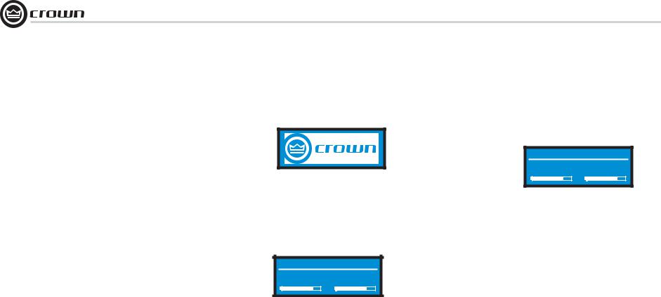
4.2.2 Basic Selections
Opening Screen: On power-up, the LCD Control Screen displays the Crown logo. After a few seconds, the fi rmware version appears, then the Attenuation screen appears.
PPoweredd Byy
(Power On) 1.0.0.5
Attenuation and Bar Meters
This screen displays the attenuation in dB and on bar meters. To change the attenuation in either channel, turn the Encoder. Attenuation changes 0.5 dB per detent when you turn the Encoder slowly, and more when you turn the Encoder quickly. The current preset name is displayed in the upper-right corner. The (M) is explained on the next page under Presets.
Attenuation Default (M)
-30.0 dB -30.0
Mute/Unmute (in the Attenuation screen)
• To mute either channel: Press and hold an Encoder knob for
1 second. The display will alternate between MUTE and the attenuation level. While the amplifi er is muted, you can adjust attenuation for each channel by turning an Encoder knob.
• To unmute either channel: Press and hold an Encoder knob again for 1 second.
Attenuation |
Default (M) |
-30.0 dB MUTE
Front Panel Lockout (in the Attenuation screen)
The amplifi er’s administrator can control access to menu mode and the amplifi er’s attenuators. This lockout can be done either by the front panel buttons or by System Architect software.
To lock or unlock the menu with the front-panel buttons: press Next and Prev simultaneously. To lock or unlock the menu with System Architect software: go to the Tools Menu > Display Screen Security and press the lockout button. If a specifi c parameter is protected, the screen says “N/A” or “Change Disabled.”
If the lockout is done from the software, the user can disable the lockout only in the software, not by pressing the front-panel buttons.
If the menu is locked and you press any button or turn an Encoder, the word “LOCKOUT” is displayed. If a specifi c parameter is protected, the screen says “N/A” or “Change Disabled.”
Now let’s look at the function of each menu selection.
page 16 |
Operation Manual |
I-Tech HD Series Power Amplifiers
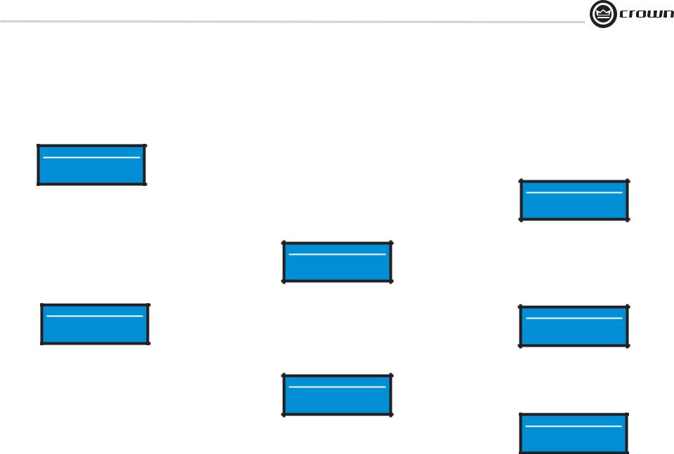
4 Advanced Operation
Sample Rate: Starting from the Attenuation screen, press Menu/Exit to go to the Sample Rate screen. The sample rate of the amplifi er’s DSP is displayed. It can be modifi ed only in System Architect software because all of the FIR fi lter settings will need to be recalculated as a result of the change. Please refer to its Help fi les. When you route a Cobranet input, the sample rate displayed here must match the Cobranet source.
Sample Rate
96 kHz
Modify in software ONLY!
Analog Input Sensitivity: Turn the left Encoder knob to change the Ch. 1 input sensitivity; turn the right Encoder knob to change the Ch. 2 input sensitivity. This screen also displays the amp gain for each channel resulting from the sensitivity settings. See Figure 4.4.
Note: If you do not see the sensitivity you need, try changing the Maximum Analog Input level in the Advanced Menu (described later). This makes different sensitivities available.
To optimize the system gain structure, see Section 3.1 in the I-Tech application Guide at www.crownaudio.com/itech/pdf/137327.pdf.
Analog Input Sensitivity
2.90 Vrms 2.90
31.5 dB Gain 31.5
Presets: A preset is a group of DSP and amplifi er settings for a particular speaker system. Turn an Encoder to view Presets 1 through 50. To recall a preset, press the Encoder, then press and hold the Encoder to confi rm. For more information on presets, see Section 4.3.
The preset currently in use is displayed in the upper right corner.
(A) Active means that the amplifi er is operating exactly according to that preset.
(M) Modified means that the amplifi er is operating according to the preset but with some settings changed.
If a preset number is fl ashing, it is not in use.
In the example shown below,
•Preset 7 is in use (it’s in the upper right corner).
•The amplifi er settings have been modifi ed (M) since Preset 7 was loaded.
•The large “7” is not fl ashing, which means that Preset 7 is in use.
Presets |
Preset7 (M) |
|
7 |
Preset7 |
|
CH1:MF-1&2 |
|
|
CH2:MF-3&4
In the example shown below, you turned down an Encoder knob two notches after loading Preset 7.
•Preset 7 is in use (it’s in the upper right corner).
•Preset 7 is active (A). That means the amplifi er is operating exactly according to that preset.
•The large “5” is fl ashing because Preset 5 is not in use.
•Preset 5’s Channel-1 label is “LF–1&2.”
•Preset 5’s Channel-2 label is “LF–3&4.”
Presets |
Preset 7(A) |
|
5 |
Preset7 |
|
CH1:LF-1&2 |
|
|
CH2:LF-3&4
Amp Mode: This screen lets you set up the amplifi er for Dual, Input Y or Bridge Mono mode. Turn an Encoder knob to choose among those three options, then press the knob to save your choice. You will be prompted to confi rm your choice. The LCD screen displays the currently selected mode.
In Dual (or Stereo) mode, both channels operate independently.
In Bridge Mono mode, both channels are summed to double the power, and the amplifi er puts out a mono signal.
In Input Y mode, Channel 1’s input signal feeds both channels, and each channel can be set to a different output level, usually for bi-amp operation.
Amp Mode
<Dual>
Turn to Set-Press to Save
Locate: Allows users to identify a specifi c amplifi er in a large network of amplifi ers without having to compare address information. Locate can be turned on/off from software and/or the front panel. Press an Encoder knob to turn on the Locate function. When on, the LCD screen fl ashes. Press the knob again to turn off the Locate function. In System Architect, the device icon has a blue outline to indicate that it is in Locate mode.
Locate
OFF
Press enc to toggle
4.2.3 ADVANCED MENU
When you see this screen, press an Encoder knob to access the selections in the Advanced Menu, described next. To get to the Advanced Menu screen from the Attenuation screen, press Menu/Exit twice, then press Next fi ve times.
Advanced Menu
Advanced Menu
Push knob for adv. menu
Operation Manual |
page 17 |
I-Tech HD Series Power Amplifiers
4 Advanced Operation
Attenuator Limits: You can set the maximum attenuation from 0 dB to –100 dB. This feature allows you to set a limit on the attenuators. Once set, attenuation cannot be adjusted beyond this level. The attenuator limit appears as a line in the attenuator bar meter.
NOTE: The attenuator setting must be below the attenuator limit that you are trying to set. For example, if the attenuator is set at –3 dB, you cannot set the attenuator limit below –3 dB unless you decrease the attenuator level.
Attenuator Limits
0.0dB 0.0
Attenuator Link You can set the attenudators to be independent or linked. Turn an Encoder knob to choose one of those options, then press the knob to save your choice.
Attenuator Link
INDEPENDENT
Turn to Set-Press to Save
Input Sources: For each channel, turn the Encoder to select analog, digital, or automatic backup source. Options are:
Analog
Digital
Digital with analog backup <Digital A-Backup> Digital with analog override <Digital A-Ovride>
Digital with analog backup: The I-Tech HD is being fed a digital signal and an analog signal. The input is currently switched to the digital signal. If it fails, the I-Tech HD switches instantly to the analog signal.
Digital with analog override: The input is switched to the digital signal, and no analog signal is applied. If an analog signal is sent, the I-Tech HD switches instantly to the analog signal. If the analog signal fails, the I-Tech HD switches to the digital signal after a delay set by the Hold Time slider in the Input Section of the System Architect page.
Input Sources
<Analog> <Digital>
page 18
Analog Source Select: Turn the left Encoder knob to select Analog 1, Analog 2, or Analog 1+2 signals for Channel 1. The right Encoder does the same for Channel 2. Press the knob to confi rm your selection.
Analog 1 is Analog input Channel 1. Anolog 2 is Analog input Channel 2.
Analog 1 +2 is Analog input Channels 1 and 2.
Analog Source Select
Analog Analog
1 2
Maximum Analog Input: Turn an Encoder to select the maximum input level to the amplifi er: +21 dBu or +15 dBu. Press the knob to confi rm your selection. Note: Changing this value changes the range of sensitivities available to the amplifi er.
For more information see Figure 4.4 and the I-Tech Sensitivity Charts in the Appendix of the I-Tech Application Guide. It is available online at www. crownaudio.com/itech/pdf/137327.pdf.
Maximum Analog Input
+15dBu
Turn to Set-Press to Save
Digital Source Select: Turn the left Encoder knob to select the digital source for Channel 1: AES or Cobranet. The right Encoder does the same for Channel 2. Press the knob to confi rm your choice.
Digital Source Select
AES <Cobra
net>
AES Source Select: Turn the left Encoder knob to select the digital source for Channel 1: AES1, AES2, or AES1+2. The right Encoder does the same for Channel 2. Press the knob to confi rm your choice.
AES 1 is AES input Channel 1. AES 2 is AES input Channel 2.
AES 1 +2 is AES input Channels 1 and 2.
AES Source Select
AES |
AES |
1 |
2 |
AES Input Trim: Turn the left Encoder knob to vary the gain of the AES digital signal for Channel 1: -100.0 dB to +20 dB. The right Encoder does the same for Channel 2. See Figure 4.4 for more information.
AES Input Trim
0.0 dB 0.0
AES Input Status: “Lock” indicates that an AES cable is plugged in and the amplifi er is receiving (and locking to) the AES clock pulse. “No Lock” means that the amplifi er is not receiving, or is not locking to the AES clock pulse.
AES Input Status
No Lock
CobraNet Source Select: Turn the left Encoder knob to select the CobraNet source for Channel 1: Cnet1, Cnet2, or Cnet 1+2. The right Encoder does the same for Channel 2. Press the knob to confi rm your choice.
Cnet1 is Bundle A. Cnet2 is Bundle B.
Cnet 1+2 is Bundles A+B.
Cobranet Source Select
Cnet 1 |
Cnet 2 |
CobraNet Input Trim: Turn the left Encoder knob to vary the gain of the CobraNet digital signal for Channel 1: -100.0 dB to +20 dB. The right Encoder does the same for Channel 2. See Figure 4.4 for more information.
Cobranet Input Trim
0.0dB 0.0
Operation Manual
 Loading...