


 Loading...
Crestron C2N/C2NI-CB Series
Cameo™ Keypads
Operations & Installation Guide

This document was prepared and written by the Technical Documentation department at:
Crestron Electronics, Inc.
15 Volvo Drive
Rockleigh, NJ 07647
1-888-CRESTRON
All brand names, product names and trademarks are the property of their respective owners. ©2006 Crestron Electronics, Inc.

Crestron C2N/C2NI-CB Series |
Cameo™ Keypads |
Contents
Cameo™ Keypads: C2N/C2NI-CB Series |
1 |
Introduction...................................................................................... |
1 |
Features and Functions .......................................................... |
1 |
Specifications......................................................................... |
3 |
Physical Description .............................................................. |
4 |
Industry Compliance.............................................................. |
8 |
Setup................................................................................................. |
9 |
Network Wiring..................................................................... |
9 |
Identity Code ....................................................................... |
10 |
Assembly and Installation ................................................... |
12 |
Programming Software .................................................................. |
23 |
Earliest Version Software Requirements for the PC.................. |
23 |
Programming with Crestron SystemBuilder or D3 Pro.......... |
24 |
Programming with SIMPL Windows.................................. |
25 |
Uploading and Upgrading.............................................................. |
29 |
Communication Settings...................................................... |
29 |
Uploading a SIMPL Windows Program.............................. |
32 |
Firmware Upgrade............................................................... |
35 |
Problem Solving............................................................................. |
38 |
Troubleshooting................................................................... |
38 |
Further Inquiries .................................................................. |
38 |
Future Updates..................................................................... |
39 |
Appendix: Template for Flush Mounting Hole ............................. |
40 |
Return and Warranty Policies ........................................................ |
41 |
Merchandise Returns / Repair Service ................................ |
41 |
CRESTRON Limited Warranty .......................................... |
41 |
Operations & Installation Guide - DOC. 6346A |
Contents • i |

Crestron C2N/C2NI-CB Series |
Cameo™ Keypads |
Cameo™ Keypads: C2N/C2NI-CB
Series
Introduction
Features and Functions
The Crestron® C2N/C2NI-CB Series Cameo keypads are a new generation of wall-mounted user interfaces that can be part of any Crestron total solution control system network (Cresnet®). The keypads are available in three versions: C2N-CBF, Flush Mount (no back box required) for domestic and international installation; C2N-CBD, Standard Mount (Decora® style), back box installation, for domestic installation; and C2NI-CBUK, Standard Mount, optional UK-style back box, for UK installation.
For maximum flexibility in all configurations, a complete set of button caps and spacers in three sizes is included with every keypad. The installer can customize and configure up to six backlit caps, for “rocker” left/right action, single press operation, or press and hold mode—up to 18 functions in total.
Functional Summary
•Six switches, each programmable for left/right “rocker” action, single press operation, or press/hold mode, enabling up to 18 functions
•Button caps and spacers supplied in single-, two-, and threebutton configurations—any combination may be used
•LED feedback and switch backlighting intensity are individually programmable
•Exclusive flush-mount, Decorator style, or traditional mounting installation
Operations & Installation Guide - DOC. 6346A |
Cameo™ Keypads: C2N/C2NI-CB Series • 1 |

Cameo™ Keypads |
Crestron C2N/C2NI-CB Series |
The basic Cameo keypad colors are black, white, and almond. The keypad’s colors and finishes can be used to accent a home’s colors, wall coverings, or décor. Additional designer colors are available. (Contact a Crestron customer service representative for details.)
Mounting options include a choice of installation as a standalone device using Crestron’s exclusive flush-mounting system; or, for the domestic keypads, Decorator installation in a conventional gang-box using standard Decora® style faceplates; or for the UK-style models, traditional mounting (electrical box optional). The flush-mounting system is the ultimate low-profile appearance that results in a footprint that is up to 75% smaller than a standard Decora style faceplate, and blends into any room effortlessly. Refer to Assembly and Installation procedures, which start on page 12, for details.
Each Cameo keypad is supplied with six single-row button caps, three double-row button caps, and two triple-row button caps as well as two single-row spacers, one double-row spacer, and one triple-row spacer.
All switches on the keypad are functionally identical. White feedback LEDs to the left of each row are independently addressable and indicate which switches are active. The intensity of the feedback LEDs is programmable from 0 to 100%. Button caps have white LED backlighting that is programmable from 0 to 100% intensity as well. In certain circumstances, such as when using black button caps, true backlighting is not practical. Instead, the program can use the feedback LEDs to perform a backlighting function, turning them all on but at a fixed percentage of their active state intensity.
For programming details, refer to “Cameo Symbol in Programming Manager,” on page 27.
2 • Cameo™ Keypads: C2N/C2NI-CB Series |
Operations & Installation Guide - DOC. 6346A |

Crestron C2N/C2NI-CB Series |
Cameo™ Keypads |
Specifications
The following table summarizes the specifications of the keypads.
Specifications for the Keypads
SPECIFICATION |
|
|
DETAILS |
Cresnet Power Usage |
3 Watts (0.125 Amps @ 24 VDC) |
||
Default Net ID |
|
25 |
|
Control System Update Files 1, 2, 3 |
|
Version 2.004.CUZ or later |
|
2-Series Control System |
|
||
CNMSX-AV/PRO |
|
Version 5.14.02X.UPZ or later |
|
CNRACKX/-DP |
|
Version 5.14.02W.UPZ or later |
|
CEN/CN-TVAV |
|
Version 5.12.63V.UPZ or later |
|
ST-CP |
|
Version 4.02.4S.UPZ or later |
|
C2N-CB-Series Firmware |
|
C2N-CB.v2.10.upg or later |
|
Environmental Temperature |
32° to 113°F (0° to 45°C) |
||
Humidity |
|
10% to 90% RH (non-condensing) |
|
Overall Dimensions: |
|
Height: |
3.20 in (8.13 cm) |
Flush Mount Model |
|
||
|
|
Width: |
1.73 in (4.38 cm) |
|
|
Depth: |
1.52 in (3.86 cm)4 |
Decorator Style Model |
Height: |
4.12 in (10.47 cm) |
|
|
|
Width: |
1.80 in (4.56 cm) |
|
|
Depth: |
1.52 in (3.86 cm)4 |
UK Style Model |
Height: |
3.38 in (8.58 cm) |
|
|
|
Width: |
3.38 in (8.58 cm) |
|
|
Depth: |
1.52 in (3.86 cm)4 |
Weight |
|
2.6 oz (73 g) – Flush mount |
|
|
|
3.1 oz (87 g) – Decorator style |
|
|
|
2.5 oz (70 g) – UK Style |
|
1.The latest versions can be obtained from the Crestron website. Refer to NOTE after last footnote.
2.Crestron 2-Series control systems include the AV2 and PRO2. Consult the latest Crestron Product Catalog for a complete list of 2-Series control systems.
3.Filenames for CNX and ST-CP update files have a UPZ extension. Files on the website may be .zip or self-extracting .exe files containing the .cuz or .upz file. All can be obtained from the Downloads section of the Crestron website. To avoid program problems, make sure you are using the update file with the correct suffix letter (e.g., S, V, W, X).
4.The depth of the Keypad is listed without the Cresnet connector (approximately 0.45 in) or clearance for the wiring.
NOTE: Crestron software and any files on the website are for Authorized Crestron dealers and Crestron Authorized Independent Programmers
Operations & Installation Guide - DOC. 6346A |
Cameo™ Keypads: C2N/C2NI-CB Series • 3 |
Cameo™ Keypads |
Crestron C2N/C2NI-CB Series |
(CAIP) only. New users may be required to register to obtain access to certain areas of the site (including the FTP site).
Physical Description
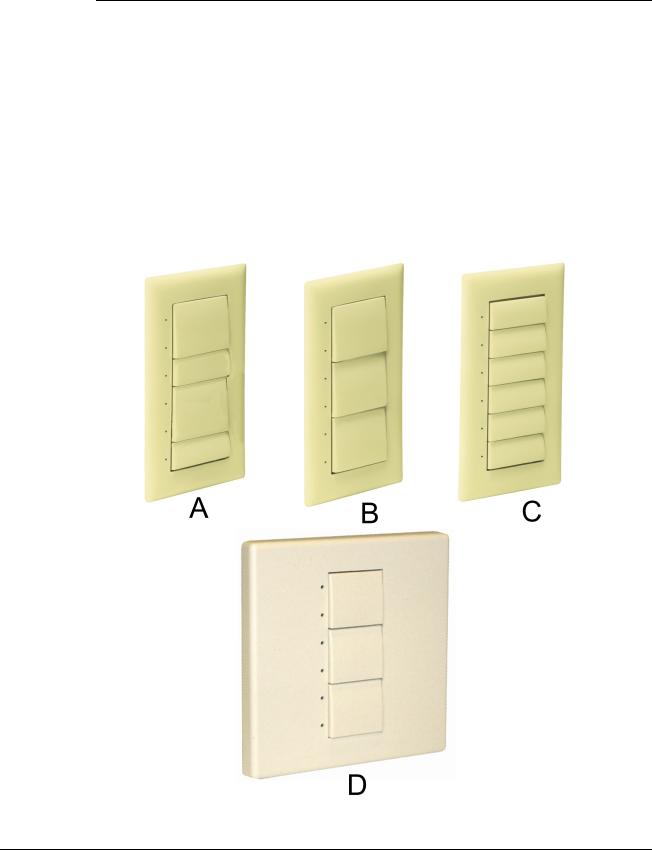
The number of active switches on a keypad can be 1, 2, 3, 4, 5, or 6. Active switches and spacers can be mixed and arranged as needed to suit a particular application. LEDs along the side of the keypad identify the active switches.
Each keypad has a mini Cresnet network port labeled 24 Y Z G. The port provides for operating power and for communication to/from the keypad.
Keypad Physical Views
4 • Cameo™ Keypads: C2N/C2NI-CB Series |
Operations & Installation Guide - DOC. 6346A |

Crestron C2N/C2NI-CB Series |
Cameo™ Keypads |
The previous illustration shows three of many possible flush mount configurations: two double-row switches with two single-row switches (A); three double-row switches (B); and six single-row switches (C), all with the LED indicators on the left. A UK-style configuration with three double-row switches is also shown (D). The button caps are tapered and are arranged here in a shingle style with the narrow part of the button cap at the top. Each button cap can, however, be arranged in either orientation, and the overall keypads can be installed with the LEDs on the right. Spacers are flat and flush with the front of the bezel surface. Button caps are laser-engravable using the Crestron Engraver software; spacers are not. The engraving software provides up to three fields for each button cap to allow for the left/right and center press functions, permits multiple lines of text, and also allows you to specify the orientation of each button cap. The Crestron Engraver software, Version 2.4 or later, is available from the Crestron website.
The following illustrations provide overall dimensions of the three keypad styles.
Operations & Installation Guide - DOC. 6346A |
Cameo™ Keypads: C2N/C2NI-CB Series • 5 |
Cameo™ Keypads |
Crestron C2N/C2NI-CB Series |
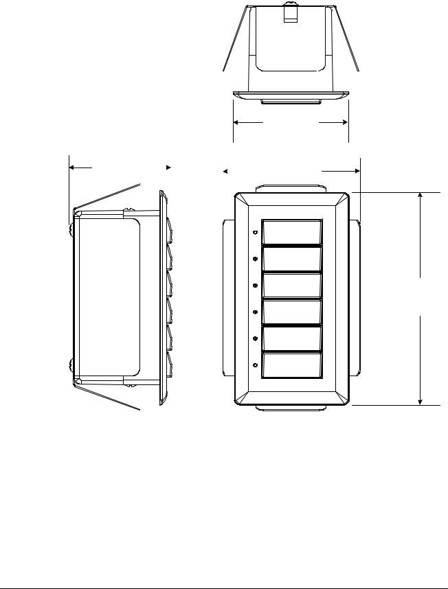
Keypad Overall Dimensions – Flush Mount Configuration
1.73 in
(4.38 cm)
1.52 in |
|
|
|
|
|
2.06 in |
|
|
|
||||
(3.86 cm) |
|
|
|
(5.23 cm) |
||
|
|
|
||||
|
|
|
|
|
|
|
|
|
|
|
|
|
|
3.20 in
(8.13 cm)
6 • Cameo™ Keypads: C2N/C2NI-CB Series |
Operations & Installation Guide - DOC. 6346A |

Crestron C2N/C2NI-CB Series |
Cameo™ Keypads |
Keypad Overall Dimensions – Decorator Mount Configuration
1.52 in |
|
|
|
1.80 in |
|||
(3.86 cm) |
|
|
|
|
|
(4.56 cm) |
|
|
|
|
|
|
|
|
|
|
|
|
|
|
|
|
|
|
|
|
|
|
|
|
|
|
|
|
|
|
|
|
|
|
|
|
|
|
|
|
|
|
|
|
|
|
|
|
|
4.12 in
(10.47 cm)
Operations & Installation Guide - DOC. 6346A |
Cameo™ Keypads: C2N/C2NI-CB Series • 7 |
Cameo™ Keypads |
Crestron C2N/C2NI-CB Series |
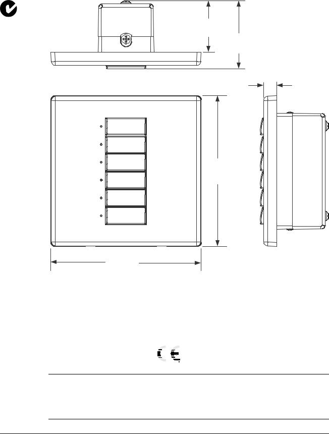
Keypad Overall Dimensions – UK-Style Configuration
1.14 in
(2.89 cm)
1.52 in
(3.86 cm)
0.30 in
(0.76 cm)
3.38 in
(8.58 cm)
3.38 in
(8.58 cm)
Industry Compliance
As of the date of manufacture, the keypads have been tested and found to comply with specifications for CE marking and standards per EMC and Radiocommunications Compliance Labelling.
NOTE: This device complies with part 15 of the FCC rules. Operation is subject to the following two conditions: (1) this device may not cause harmful interference, and (2) this device must accept any interference received, including interference that may cause undesired operation.
8 • Cameo™ Keypads: C2N/C2NI-CB Series |
Operations & Installation Guide - DOC. 6346A |

Crestron C2N/C2NI-CB Series |
Cameo™ Keypads |
Setup
Network Wiring
CAUTION: In order to ensure optimum performance over the full range of your installation topology, Crestron Certified Wire, and only Crestron Certified Wire, should be used. Failure to do so may incur additional charges if support is required to identify performance deficiencies as a result of using improper wire.
CAUTION: Use only Crestron power supplies for Crestron equipment. Failure to do so could cause equipment damage or void the Crestron warranty.
CAUTION: Provide sufficient power to the system. Insufficient power can lead to unpredictable results or damage to the equipment. Please use the Crestron Power Calculator to help calculate how much power is needed for the system (http://www.crestron.com/calculators).
When calculating the length of wire for a particular Cresnet run, the wire gauge and the Cresnet power usage of each network unit to be connected must be taken into consideration. Use Crestron Certified Wire only. If Cresnet units are to be daisy-chained on the run, the Cresnet power usage of each network unit to be daisy-chained must be added together to determine the Cresnet power usage of the entire chain. If the unit is a home-run from a Crestron system power supply network port, the Cresnet power usage of that unit is the Cresnet power usage of the entire run. The wire gauge and the Cresnet power usage of the run should be used in the following equation to calculate the cable length value on the equation’s left side.
Cable Length Equation
L < |
40,000 |
Where: L = Length of run (or chain) in feet. |
R x P |
R = 6 Ohms (Crestron Certified Wire: 18 AWG (0.75 MM2)) |
|
|
P = Cresnet power usage of entire run (or chain). |
Make sure the cable length value is less than the value calculated on the right side of the equation. For example, a Cresnet run drawing 20 watts should not have a length of run more than 333 feet.
Operations & Installation Guide - DOC. 6346A |
Cameo™ Keypads: C2N/C2NI-CB Series • 9 |

Cameo™ Keypads |
Crestron C2N/C2NI-CB Series |
NOTE: All Crestron certified Cresnet wiring must consist of two twisted pairs. One twisted pair is the +24V conductor and the GND conductor, and the other twisted pair is the Y conductor and the Z conductor.
NOTE: When daisy-chaining Cresnet units, strip the ends of the wires carefully to avoid nicking the conductors. Twist together the ends of the wires that share a pin on the network connector, and tin the twisted connection. Apply solder only to the ends of the twisted wires. Avoid tinning too far up the wires or the end becomes brittle. Insert the tinned connection into the Cresnet connector and tighten the retaining screw. Repeat the procedure for the other three conductors.
NOTE: For larger networks (i.e., greater than 28 network devices), it may become necessary to add a Cresnet Hub/Repeater (CNXHUB) to maintain signal quality throughout the network. Also, for networks with lengthy cable runs, it may be necessary to add a Hub/Repeater after only 20 devices.
Identity Code
Every equipment and user interface within the network requires a unique identity code (Net ID). These codes are two-digit hexadecimal numbers from 03 to FE. (Net ID 02 is reserved for master control units). The Net IDs reside within all Cresnet devices (hardware) and must match the Net ID as specified in the software (SIMPL Windows) that runs the system.
Refer to “Setting the Net ID in Device Settings” on page 27 for details of the SIMPL Windows procedure.
The Net ID of the keypad has been factory set to 25. The Net IDs of multiple keypads in the same system must be unique. Net IDs are changed from a personal computer (PC) via the Crestron Toolbox.
NOTE: For detailed information on establishing communication between the PC and control system, refer to “Communication Settings” on page 29. If communication cannot be established, refer to the “Troubleshooting Communications” section in the latest version of the 2-Series Control System Reference Guide (Doc. 6256), or the respective Operations Guide for the control system. Both are available from the Crestron website (http://www.Crestron.com/manuals).
10 • Cameo™ Keypads: C2N/C2NI-CB Series |
Operations & Installation Guide - DOC. 6346A |
Crestron C2N/C2NI-CB Series |
Cameo™ Keypads |
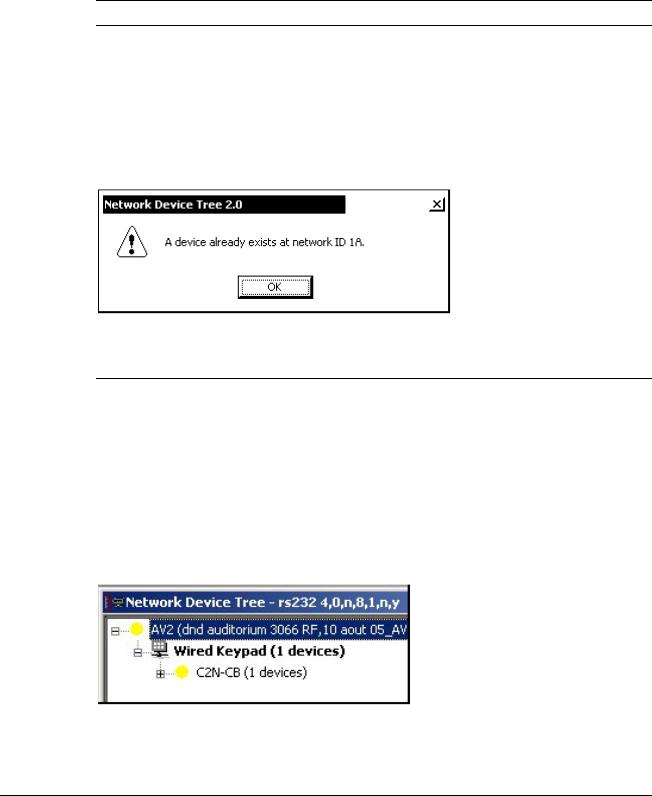
The Crestron Toolbox provides several methods to easily set or change device Net IDs for any device on the network. The following method permits you to change the Net ID of any device in the network through the “Network Device Tree” window.
NOTE: This method prevents you from setting duplicate IDs.
This method lets you manually set the Net ID for any device in the network, can be used to set any known Net IDs that require changing, and may also be used for non-TSID equipment. This method will not permit you to choose an ID already in use by another device. A warning message will appear if you attempt to use an ID that is already in use.
Duplicate Net ID Warning Message
This method does not change the Net ID as assigned in SIMPL windows. Refer to page 27 for the SIMPL Windows ID change procedure.
NOTE: You may also use SystemBuilder to perform Network ID setup.
1.Connect all network devices to the control system.
2.Open Crestron Toolbox and establish communications (refer to page 29).
3.Select the Network Device Tree  icon, or select Tools | Network Device Tree.
Network Device Tree
4.Right-click on the device Net ID, and when the sub-menu appears, select Change Network ID from the sub-menu.
Operations & Installation Guide - DOC. 6346A |
Cameo™ Keypads: C2N/C2NI-CB Series • 11 |
Loading...