


 Loading...
Crestron CNMSX |
Integrated Control System |
Contents
Integrated Control System: CNMSX |
1 |
Description................................................................................................................................. |
1 |
Functional Description ................................................................................................ |
1 |
Configuration Differences........................................................................................... |
1 |
Physical Description.................................................................................................... |
2 |
Leading Specifications............................................................................................................... |
9 |
Setup ........................................................................................................................................ |
11 |
Rack Mounting.......................................................................................................... |
11 |
Bussing Strip Installation .......................................................................................... |
12 |
Network Wiring......................................................................................................... |
12 |
Hardware Hookup ..................................................................................................... |
14 |
Programming the LCD Display (available on CNMSX-PRO only)........................................ |
15 |
Front Panel Editor ..................................................................................................... |
15 |
Creating a Page with Front Panel Editor ................................................................... |
16 |
Object Types ............................................................................................................. |
18 |
Loading Crestron Control Software......................................................................................... |
18 |
Installing Crestron Development Tools..................................................................... |
18 |
Memory ..................................................................................................................... |
19 |
Initial Setup ............................................................................................................... |
19 |
File Types.................................................................................................................. |
21 |
Obtaining Communications....................................................................................... |
24 |
Troubleshooting Communications ............................................................................ |
26 |
Loading the System Program .................................................................................... |
29 |
Testing the Permanent Memory Image ..................................................................... |
30 |
Loading Touchpanels ................................................................................................ |
30 |
Updating the Control System .................................................................................... |
31 |
Special Consideration for Updating the Control System........................................... |
33 |
Problem Solving ...................................................................................................................... |
33 |
Possible Problems with the CNMSX ........................................................................ |
33 |
Serial Communication Difficulties with Other Devices Connected to the CNMSX.34 |
|
Further Inquiries........................................................................................................ |
36 |
Future Updates .......................................................................................................... |
36 |
Software License Agreement................................................................................................... |
37 |
Return and Warranty Policies.................................................................................................. |
39 |
Merchandise Returns / Repair Service ...................................................................... |
39 |
CRESTRON Limited Warranty ................................................................................ |
39 |
Operations Guide - DOC. 8118B |
Contents • i |

Crestron CNMSX |
Integrated Control System |
Integrated Control System:
CNMSX
Description
Functional Description
The CNMSX is an integral part of Crestron’s new generation of control system technology featuring the newest series of Ethernet/local area network (LAN) compatible control systems. The CNMSX is an integrated control system with eight infrared (IR)/serial ports, six bidirectional RS-232/422/485 ports, eight digital/analog input and digital output ports, eight isolated relays, and an integrated 110/220 VAC (75W) power supply.
Expansion Slots
There is also room for growth; the unit (depending on configuration) offers four expansion slots. One of the slots features Crestron’s exclusive Direct Processor Access (DPA) port for Ethernet/LAN expansion of the control network. This port provides high-speed access directly to the processor while maintaining bandwidth network connections. The DPA currently supports the CNXENET (& CNXENET+) 10 BaseT Ethernet cards with future support for Firewire, ATM, 100BaseT, and popular interfaces. The other three card slots offer system expansion with a variety of plug-in cards.
LCD Display (available on CNMSX-PRO only)
An 80-character (two 40-character lines) liquid crystal display (LCD) display and an extended bank of LED indicators are located on the front panel to provide extended features, status information, and troubleshooting indications.
Configuration Differences
There are two CNMSX configurations available: the PRO and AV. The PRO is the flagship product in Crestron’s new generation of control systems. It is the model that has all the features mentioned in the previous section. The AV is a cost-competitive alternative to the PRO. The AV has all the features of the PRO, except for the extended bank of status and activity LEDs, front panel LCD screen, and the network analyzer feature. A “card cage” (CNXCAGE) providing three expansion slots is
Operations Guide - DOC. 8118B |
Integrated Control System: CNMSX • 1 |
Integrated Control System |
Crestron CNMSX |
An asterisk (*) indicates that the feature is not standard (though may be optional) on the AV configuration.
An asterisk (*) indicates that the feature is not standard (though may be optional) on the AV configuration.
optional on the AV. Refer to the table below for a concise list of configuration features.
CNMSX Configuration Differences
FEATURES |
CNMSX-PRO |
CNMSX-AV |
|
|
|
|
|
|
Integrated 110/220 VAC Power Supply |
Standard |
Standard |
2 Crestron Network Ports |
Standard |
Standard |
8 Isolated Relays |
Standard |
Standard |
|
|
|
8 IR/Serial Ports |
Standard |
Standard |
6 Bidirectional RS-232/422/485 Ports |
Standard |
Standard |
|
|
|
8 Digital/Analog Input & Digital Output Ports |
Standard |
Standard |
2 Computer (RS-232) Ports |
Standard |
Standard |
Direct Processor Access (DPA) Slot |
Standard |
Standard |
Expansion Slots |
Standard |
Optional |
CNXENET or CNXENET+ (field installed into DPA slot) |
Optional |
Optional |
Reverse LCD Display |
Standard |
Not Available |
|
|
|
Extended Bank of Status and Activity LEDs |
Standard |
Not Available |
COM Analyzer |
Standard |
Not Available |
Physical Description
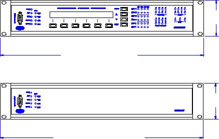
The CNMSX is housed in a black enclosure with silk-screened labels on the front and rear panels. On the front panel there is a single RS-232 computer port, standard LEDs, two reset buttons, a reverse LCD display* with menu function and selection buttons, and an extended bank of LED indicators*. The front panel of the CNSMXPRO and AV are shown below.
CNMSX-PRO Front Panel
3.469 in
(8.811 cm)
19.000 in (48.260 cm)
WITH OPTIONAL MOUNTING EARS 17.025 in (43.244 cm)
WITHOUT OPTIONAL MOUNTING EARS
CNMSX-AV Front Panel
3.469 in
(8.811 cm)
19.000 in (48.260 cm)
WITH OPTIONAL MOUNTING EARS 17.025 in (43.244 cm)
WITHOUT OPTIONAL MOUNTING EARS
Located on the rear panel, shown on the next page for each configuration, there are three open card slots*, two network connectors, DPA slot, a single RS-232 computer port, eight IR/serial ports, eight I/O ports, eight relay ports, six COM ports, and a 110/220 VAC male connector for power.
2 • Integrated Control System: CNMSX |
Operations Guide - DOC. 8118B |

Crestron CNMSX |
Integrated Control System |
CNMSX-PRO Rear Panel with Optional DPA Expansion Card and Rack Mounting Ears
Installed
CNMSX-AV Rear Panel with Optional DPA Expansion Card and Rack Mounting Ears Installed
Rubber feet are supplied and can be attached to the base of the unit for stability and to prevent slippage when resting on a flat surface. The unit may also be rack mounted by attaching metal flanges, also known as ears (supplied), to each end.
CNMSX Ports
A number of ports are provided on the front and rear panels of the CNMSX. Refer to the description of each below.
CRESNET
CRESNET 4-Wire and 6-Pin Connectors
On the rear panel there are two network connectors: 4-wire and modular. The 4-pin male connector (typical Crestron network port labeled 24 Y Z G) and 6-wire RJ-type connector are used for expansion to Cresnet and SmarTouch peripherals. Depending on the expansion slot load, there is a 50 W maximum load rating. The ports are wired in parallel.
NOTE: If using the 4-wire connector, review the latest revision of the network interconnection drawing (Doc. 5411).
NOTE: If using the modular connector, review the latest revision of the Network Modular Cable Requirements (Doc. 5682). Most 4-conductor phone cables are wired in a crisscross fashion and are not compatible with Crestron equipment.
The documents mentioned in the two preceeding notes can be obtained from the Downloads page (CABLES and MANUAL Libraries) of the Crestron website (www.crestron.com). Search for the CRESNET.PDF and MODULAR.PDF files.
Operations Guide - DOC. 8118B |
Integrated Control System: CNMSX • 3 |
Integrated Control System |
Crestron CNMSX |
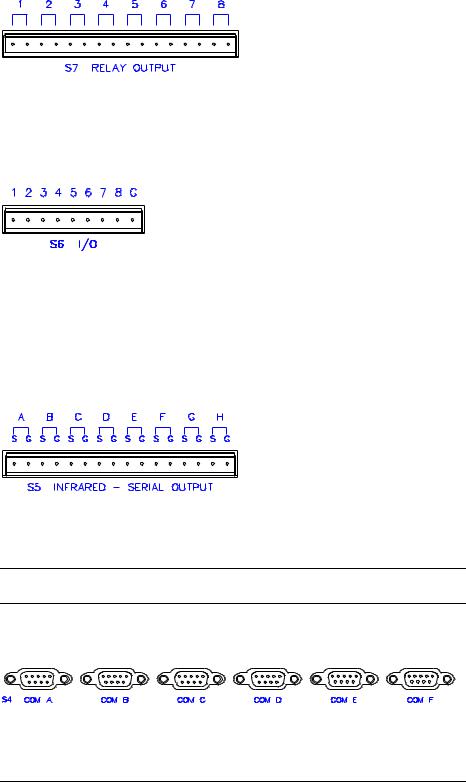
RELAY OUTPUT
Relay Output Connector
On the rear panel there are eight normally open, isolated relays. Each relay is rated 1A, 30 VAC/DC; MOV arc suppression is provided across contacts for use with “real world” loads.
I/O
I/O Connector
On the rear panel there are eight software programmable analog and digital inputs as well as digital outputs. Digital outputs offer 250mA sync from maximum 24 VDC; catch diodes for use with “real world” loads. Digital inputs are rated 0 - 24 VDC, 20K ohms input impedance, logic threshold 1.25 VDC. Analog inputs are rated 0 - 10 VDC, protected to 24 VDC maximum, 20K ohms input impedance; pinprogrammable 2K ohms pullup resistor to +5V.
INFRARED - SERIAL - RS 232
Infrared - Serial Output Connector
On the rear panel there are eight serial outputs for IR, one-way RS-232, or serial interface. Each output is labeled S (signal) and G (ground). Infrared output is rated up to 1.2 MHz. Serial protocols include RS-232.
NOTE: RS-232 levels on the infrared – serial output connectors provide a 0 – 5V range, which may not be compatible with all devices.
COM (A - F)
COM (A - F) Connectors
On the rear panel there are six software programmable bidirectional serial ports for RS-232, RS-422, or RS-485 communication with hardware and software handshaking. Speeds are rated up to 230,400 bps.
NOTE: The pinout of each 9-pin port is non-standard (refer to table after this note, titled “Non-Standard COM Pinout” ); it contains RS-422 pins in addition to RS-232.
4 • Integrated Control System: CNMSX |
Operations Guide - DOC. 8118B |
Crestron CNMSX |
Integrated Control System |
This may result in a conflict with some equipment and therefore do not use all nine pins. Only the required pins for each communication type should be connected.
NOTE: To support RS-485, tie pin 1 (RXD-) to pin 9 (TXD-) and pin 4 (TXD+) to pin 6 (RXD+) in the cable (refer to table after this note, titled “COM Pinout to RS485 Bus”.
Non-Standard COM Pinout
PIN |
DIRECTION |
DESCRIPTION |
|
|
|
1* |
To CNMSX |
(RXD-) RS-422 Receive Data (Idles low) |
2 |
To CNMSX |
(RXD) RS-232 Received Data |
3 |
From CNMSX |
(TXD) RS-232 Transmitted Data |
4 |
From CNMSX |
(TXD+) RS-422 Transmit Data (Idles high) |
5 |
|
RS-232 and RS-422 Signal Common |
6 |
To CNMSX |
(RXD+) RS-422 Receive Data (Idles high) |
7 |
From CNMSX |
(RTS) RS-232 Request to Send |
8 |
To CNMSX |
(CTS) RS-232 Clear to Send |
9 |
From CNMSX |
(TXD-) RS-422 Transmit Data (Idles low) |
Where: *= RS-422 transmit and receive are balanced signals requiring two lines plus a ground in each direction. RXD+ and TXD+ should idle high (going low at start of data transmission). RXDand TXDshould idle low (going high at start of data transmission). If necessary, RXD+/RXDand TXD+/TXDmay be swapped to maintain correct signal levels.
COM Pinout to RS-485 Bus
COM (DB9) CONNECTOR |
RS-485 BUS |
|
|
Tie Pins 1 & 9 |
- |
Tie Pins 4 & 6 |
+ |
Pin 5 |
G |
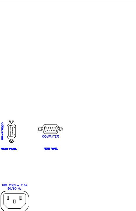
COMPUTER
Computer Connectors
These 9-pin DB9 female connectors (one on front panel and one on rear) are used when programming with a PC. Each port is modem compatible. The modem cable is not included.
100 - 250V ~ 2.3A 50/60 Hz (Power Supply)
Universal Power Supply Connector
On the rear panel there is an internal universal power supply connector. Use the supplied power cord to connect to an AC outlet.
Operations Guide - DOC. 8118B |
Integrated Control System: CNMSX • 5 |

Integrated Control System |
Crestron CNMSX |
CNMSX Indicators
A number of indicators are provided on the front panel of the CNMSX. Refer to the description of each below.
PWR
This LED illuminates when the unit is connected to and receives power from an AC outlet.
NET
This LED illuminates when the central processing unit (CNXPU) is processing or communicating with system hardware (i.e., button pressed at local panel or network panel, data being sent out serial port, or permanent memory image being created).
ERR
This LED illuminates when an error condition is detected by the CNXPU. This may be the result of hardware or software failure, hardware incompatibility with software definitions, or a programming error. To decipher content, examine the message available from the menu function buttons.
NOTE: The next four LEDs are active only if the DPA Expansion Card (which is field installed) occupies the DPA slot.
TXD (LAN)
This LED illuminates during transmission of ethernet data from the DPA slot.
RXD (LAN)
This LED illuminates during reception of ethernet data by the DPA slot.
LNK (LAN)
This LED illuminates when there are attachements to the ethernet network.
ERR (LAN)
This LED illuminates when an ethernet protocol error is detected.
NOTE: The remaining LEDs mentioned after this note are available on the PRO configuration, but not available on the AV configuration.
COM TX (A - F)
These LEDs illuminate during transmission of data to serial devices attached to respective COM ports.
COM RX (A - F)
These LEDs illuminate during reception of data from serial devices attached to respective COM ports.
COM RTS (A - F)
These LEDs illuminate to reflect the state of RTS (A - F). An illuminated LED means that the RTS line is high. If no handshaking is specified, the RTS line will be high and therefore, the associated LED is also high. When RTS flow control is enabled, RTS indicates the unit is ready to receive data from serial devices attached to respective COM ports.
6 • Integrated Control System: CNMSX |
Operations Guide - DOC. 8118B |
Crestron CNMSX |
Integrated Control System |
Main Menu
(Default LCD Display)
COM CTS (A - F)
These LEDs illuminate to reflect the state of CTS (A - F). An illuminated LED means that the CTS line is high. When CTS flow control is enabled, CTS indicates the serial devices on the respective COM ports are ready to accept data from the unit.
IR - SERIAL (A - H)
These LEDs illuminate during activity on respective IR/SERIAL lines.
INPUT - OUTPUT (1 - 8)
These LEDs illuminate when the input voltage threshold for respective I/O ports are exceeded or when the output is active.
RELAY (1 - 8)
These LEDs illuminate when respective relay is closed.
SLOT (1 - 3)
These LEDs illuminate when a CNX expansion card is inserted into respective slots.
CNMSX Buttons
Two buttons are provided on the front panel of the CNMSX. Refer to the description of each below.
HW-R
Depression of this button initiates physical reset of the system.
SW-R
Depression of this button in combination with the HW-R button (as described in step 5 of "Troubleshooting Communications" on page 26) performs an overload/reset.
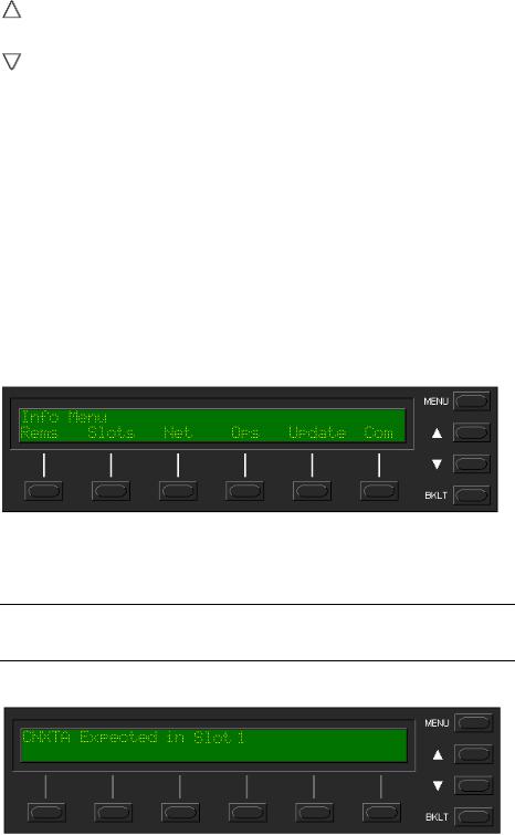
CNMSX LCD Display
The front panel of the CNMSX-PRO incorporates a reverse mode (yellow on black) LCD display, shown below. The screen contains two lines with 40 characters per line; it is used to extend features and gain access to the system including the SIMPL program. To the right of the display are four menu selection buttons. These buttons permit the user to navigate through the menus and also to control the brightness of the display backlight. Below the display are six menu function buttons. These buttons offer extended features of the CNMSX. For details, refer to "Programming the LCD Display (available on CNMSX-PRO only)" on page 15.
LCD Display with Menu Selection and Menu Function Buttons
Operations Guide - DOC. 8118B |
Integrated Control System: CNMSX • 7 |
Integrated Control System |
Crestron CNMSX |
||
Menu Selection Buttons |
MENU |
|
|
|
This menu selection button functions as a return and will eventually bring the screen |
||
|
display to the menu default state. |
|
|
|
This button scrolls the listed information UP. |
|
|
|
This button scrolls the listed information DOWN. |
|
|
|
BKLT |
|
|
|
This button adjusts the brightness of the LCD backlight and the front panel LEDs. |
||
Menu Function Buttons |
PANEL |
|
|
|
This menu function button displays a programmable interface offering command text, |
||
|
indirect text, and hierarchical screen structure. The menu contents are subject to |
||
|
programming and an example of this display is provided in "Programming the LCD |
||
|
Display (available on CNMSX-PRO only)" on page 15. |
|
|
INFO
This button displays a default Info Menu, shown below. System information, including the loaded SIMPL program version, types of CNX expansion cards installed in the card slots, the Cresnet devices detected, the Ops/ROM version, and the communication settings, is displayed.
Default Info Menu
MSG
This button displays system error messages or alarms. If there are one or more errors, press the  menu selection button to reveal the next message.
NOTE: Error messages may be the result of hardware or software failure, hardware incompatibility with software definitions, or a programming error. After the last message has been read, the ERR front panel LED extinguishes.
Example Message
8 • Integrated Control System: CNMSX |
Operations Guide - DOC. 8118B |
Crestron CNMSX |
Integrated Control System |
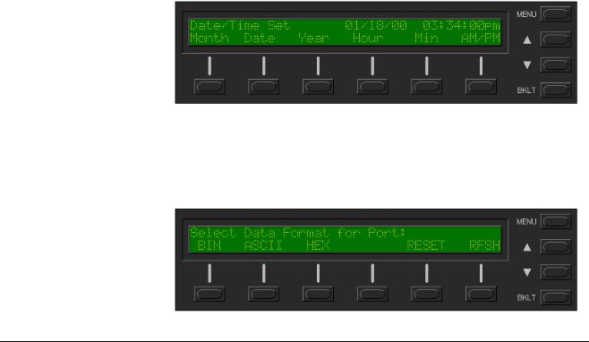
TIME
This menu can only be obtained by entering the correct access code. The default access code is 1234. Use the Viewport (Functions | Set CNX Front Panel Password) to assign a unique access code.
The default Time Menu, shown after this paragraph, permits alterations to system date and time. Selecting a date/time parameter from the menu increments it by one. Additional incremental or decremental changes can then be done by depressing the  and
and  menu selection buttons, respectively.
Default Time Menu
COM
This button monitors the transmission and reception traffic on each COM port for a given data format, as shown below in the default COM Menu. For more details refer to "Network Analyzer (available on CNMSX-PRO only)" on page 34.
Default COM Menu
Leading Specifications
The tables below and on the next page provide a summary of leading specifications for the CNMSX. Dimensions and weight are rounded to the nearest hundredth unit.
Leading Specifications of the CNMSX
1
2
SPECIFICATION |
DETAILS |
|
|
Power Requirements |
100-250 VAC, 2.3 A, 50/60 Hz Internal Universal Power Supply |
SIMPLTM Windows® |
Version 1.30.01 or later with the addition of smwlib49.exe |
CNX Upgrade File (.upz) |
Version 5.10.24X or later.2 |
Reset Buttons |
HW-R (permits physical reset of system) & |
|
SW-R (assists with overload/reset). |
The latest software versions can be obtained from the Downloads page (SIMPLWIN Library) of the Crestron website (www.crestron.com). New users are required to register in order to obtain access to the FTP site.
Filenames for CNX upgrades have a UPZ extension and can be obtained from the Downloads page (OPSYS Library) of the Crestron website. For a CNMSX with e-control™ use the latest UPZ upgrade file from the ECONTROL Library.
Operations Guide - DOC. 8118B |
Integrated Control System: CNMSX • 9 |

Integrated Control System |
Crestron CNMSX |
Leading Specifications of the CNMSX (Continued) |
|
|
3 |
NOTE: There is no restriction |
4 |
with the CNXENET+ card. |
|
SPECIFICATION |
DETAILS |
|
|
LCD Display |
(1) reverse mode (yellow on black) LCD back light; (2) lines, |
|
(40) characters per line.3 |
MaxDigitalSignals |
16373 |
MaxAnalogSignals |
2048 |
MaxNVRAM |
64K |
MaxProgramSize |
256K (no DPA card installed, CNXENET+ card installed, or |
|
CNXENET installed and its IP Address set to 0.0.0.0) |
|
100K (CNXENET card installed with valid IP Address)4 |
Dimensions & Weight |
Height: 3.47 in (8.81 cm) |
|
Width: 19.00 in (48.26 cm) |
|
Depth: 8.43 in (21.41 cm) |
|
Weight: 6.29 lb (2.85 kg) for AV |
|
Weight: 7.01 lb (3.18 kg) for PRO |
The LCD display is not available on the CNMSX-AV.
The program size restriction of 100K with the CNXENET card exists if the control system has the CNXENET installed and a valid IP address is assigned. SIMPL Windows limits the size of the compiled file to 100K only if the CNXENET has been dropped onto the DPA Card slot.
Typically, if the CNXENET is being used for remote maintenance and not for programming Ethernet devices (such as e-control touchpanels, etc), most users do not drop the CNXENET into the program in SIMPL Windows. Please note that the maximum program size is still 100K, even though SIMPL Windows states 256K during a compile. To make SIMPL Windows enforce the restriction, drop a CNXENET into the DPA Card slot.
Leading Specifications of the CNMSX Connectors
CONNECTOR |
DETAILS |
|
|
NET |
(1) 6-wire RJ-type connector and (1) 4-pin male connector for expansion |
|
to CRESNET or SmarTouch peripherals. |
|
50 Watt maximum load depending on expansion slot load |
|
|
RELAYS |
(8) normally open,isolated relays; each relay is rated 1 A, 30 VAC/DC MOV |
|
arc suppression devices across contacts for use with "real world" loads |
INPUT/OUTPUT |
(8) programmable digital/analog inputs & digital outputs; digital outputs |
|
offer 250 mA sync from maximum 24 VDC; catch diodes for use with "real |
|
world" loads; digital inputs rated for 0-24 VDC, 20 K ohms input impedance, |
|
logic threshold 1.25 VDC; analog inputs rated 1-10 VDC, protected to |
|
24 VDC maximum, 20 K ohms input impedance; programmable 2 K ohms |
|
pullup resistor (per pin, software reference to GND or closure to GND) |
|
|
IR/SERIAL |
(8) serial outputs or IR, RS-232, or serial interface; signal (S) and ground |
|
(G) pins, infrared output up to 1.2 MHz, serial protocols include RS-232 |
COM |
(6) bidirectional serial ports for RS-232, RS-422, or RS-485 communication |
|
with hardware and software handshaking; speeds up to 230,400 bps |
COMPUTER |
(2) 9-pin DB9 female connector for programming with a PC; modem |
|
compatible, null modem cable; not included |
Leading Specifications of the CNMSX Slots |
|
|
|
SLOT |
DETAILS |
1 through 3 DPA
(3) open "card cage" slots accept any "X" CRESNET control card5 Direct Processor Access expansion slot for optional local area network (LAN) interface card; CNXENET+ requires field installation and has (1) 8-wire RJ45 connector for communication acces
5 |
CNXCAGE, 3-card cage, installation required for CNMSX-AV. |
|
10 • Integrated Control System: CNMSX |
Operations Guide - DOC. 8118B |
Loading...