


Operator’s Manual
®
2-Cycle
WEEDWACKER® GAS TRIMMER
Model No. 316.791870
• SAFETY
• ASSEMBLY
• OPERATION
• MAINTENANCE
• PARTS LIST
• ESPAÑOL, P. 15
CAUTION: Before using this product, read this manual and follow all safety rules and operating instructions.
Sears, Roebuck and Co., Hoffman Estates, IL 60179, U.S.A.
Visit our website: www.sears.com/craftsman
769-02958 |
02/07 |

RULES FOR SAFE OPERATION
CALIFORNIA PROPOSITION 65 WARNING
WARNING
THE ENGINE EXHAUST FROM THIS PRODUCT CONTAINS CHEMICALS KNOWN TO THE STATE OF CALIFORNIA TO CAUSE CANCER, BIRTH DEFECTS OR OTHER REPRODUCTIVE HARM.
TABLE OF CONTENTS
Safety Rules . . . . . . . . . . . . . . . . . . . . . . . . . . . . . . . . . . . .2
Warranty . . . . . . . . . . . . . . . . . . . . . . . . . . . . . . . . . . . . . . .4
Know Your Unit . . . . . . . . . . . . . . . . . . . . . . . . . . . . . . . . .5
Oil and Fuel Information . . . . . . . . . . . . . . . . . . . . . . . . . . .6
Assembly Instructions . . . . . . . . . . . . . . . . . . . . . . . . . . . .6
Starting/Stopping Instructions . . . . . . . . . . . . . . . . . . . . . .7
Operating Instructions . . . . . . . . . . . . . . . . . . . . . . . . . . . .8
Maintenance and Repair Instructions . . . . . . . . . . . . . . . .9
Cleaning and Storage . . . . . . . . . . . . . . . . . . . . . . . . . . .11
Troubleshooting Chart . . . . . . . . . . . . . . . . . . . . . . . . . . .12
Specifications . . . . . . . . . . . . . . . . . . . . . . . . . . . . . . . . .12
Parts List . . . . . . . . . . . . . . . . . . . . . . . . . . . . . . . . . . . . .28
Service Numbers . . . . . . . . . . . . . . . . . . . . . . . .Back Cover
SPARK ARRESTOR NOTE
NOTE: For users on U.S. Forest Land and in the states of California, Maine, Oregon and Washington. All U.S. Forest Land and the state of California (Public Resources Codes 4442 and 4443), Oregon and Washington require, by law that certain internal combustion engines operated on forest brush and/or grass-covered areas be equipped with a spark arrestor, maintained in effective working order, or the engine be constructed, equipped and maintained for the prevention of fire. Check with your state or local authorities for regulations pertaining to these requirements. Failure to follow these requirements could subject you to liability or a fine. This unit is factory equipped with a spark arrestor. If it requires replacement, ask a Sears or other qualified service dealer to install the Accessory Muffler Assembly, Part #753-05169.
All information, illustrations, and specifications in this manual are based on the latest product information available at the time of printing. We reserve the right to make changes at any time without notice.
• IMPORTANT SAFETY INSTRUCTIONS •
READ ALL INSTRUCTIONS BEFORE OPERATING
•Read the instructions carefully. Be familiar with the controls and proper use of the unit.
•Do not operate this unit when tired, ill or under the influence of alcohol, drugs or medication.
•Children must not operate the unit. Teens must be accompanied and guided by an adult.
•Inspect the unit before use. Replace damaged parts. Check for fuel leaks. Make sure all fasteners are in place and secure. Replace cutting attachment parts that are cracked, chipped or damaged in any way.
•Use only Hassle Free™ XTRA QUIET Spiral Line. Never use metal-reinforced line, wire, chain or rope. These can break off and become dangerous projectiles.
•Be aware of risk of injury to the head, hands and feet.
•Clear the area to be cut before each use. Remove rocks, broken glass, nails, wire, string and other objects which may be thrown or become entangled in the cutting attachment. Clear the area of children, bystanders and pets; keep them outside a 50-foot (15 m) radius, at a minimum. Even then, they are still at risk from thrown objects. Encourage bystanders to wear eye protection. If you are approached, stop the unit immediately.
•Squeeze the throttle control and check that it returns automatically to the idle position. Make all adjustments or repairs before using the unit.
FUEL SAFETY WARNINGS
•Store fuel only in containers specifically designed and approved for the storage of such materials.
WARNING: Gasoline is highly flammable and its vapors can explode if ignited. Take the following precautions:
•Always stop the engine and allow it to cool before filling the fuel tank. Never remove the fuel tank cap or add fuel when the engine is hot. Never operate the unit without the fuel cap securely in place.
•Loosen the fuel tank cap slowly to relieve any pressure in the tank.
•Mix and add fuel in a clean, well-ventilated outdoor area where there are no sparks or flames. Remove the fuel cap slowly, and only after the engine stops. Do not smoke while fueling or mixing fuel. Wipe up any spilled fuel from the unit immediately.
•Avoid creating a source of ignition for spilled fuel. Do not start the engine until fuel vapors dissipate.
•Move the unit at least 30 feet (9.1 m) from the fueling source and site before starting the engine. Do not smoke. Keep sparks and open flames away from the area while adding fuel or operating the unit.
WHILE OPERATING
•Never start or run the unit inside a closed room or building. Breathing exhaust fumes can be fatal. Operate this unit only in a well-ventilated outdoor area.
•Wear safety glasses or goggles that meet ANSI Z87.1 standards and are marked as such. Wear ear/hearing protection when operating this unit. Wear a face or dust mask if the operation is dusty.
•Wear heavy long pants, boots, gloves and a long sleeve shirt. Do not wear loose clothing, jewelry, short pants, sandals or go barefoot. Secure hair above shoulder level.
•The cutting attachment shield must always be in place while operating the unit. Do not operate unit without both trimming lines extended, and the proper line installed. Do not extend the trimming line beyond the length of the shield.
•This unit has a clutch. The cutting attachment remains stationary when the engine is idling. If it does not, take the unit to a Sears or other qualified service dealer for an adjustment.
2
RULES FOR SAFE OPERATION
•Adjust the D-handle to your size in order to provide the best grip.
•Be sure the cutting attachment is not in contact with anything before starting the unit.
•Use the unit only in daylight or good artificial light.
•Avoid accidental starting. Be in the starting position whenever pulling the starter rope. The operator and unit must be in a stable position while starting. Refer to
Starting/Stopping Instructions.
•Use the right tool. Only use this tool for its intended purpose.
•Always hold the unit with both hands when operating. Keep a firm grip on both handles or grips.
•Keep hands, face, and feet away from all moving parts. Do not touch or try to stop the cutting attachment when it rotates.
•Do not touch the engine, gear housing or muffler. These parts get extremely hot from operation, even after the unit is turned off.
•Do not operate the engine faster than the speed needed to cut, trim or edge. Do not run the engine at high speed when not cutting.
•Always stop the engine when cutting is delayed or when walking from one cutting location to another.
•If you strike or become entangled with a foreign object, stop the engine immediately and check for damage. Do not operate before repairing damage. Do not operate the unit with loose or damaged parts.
•Use only replacement parts or accessories recommended for this tool that are distributed by Sears or a Craftsman outlet. Use of any replacement parts or accessories purchased elsewhere may be hazardous, and will also void your warranty.
•Keep unit clean of vegetation and other materials. They may become lodged between the cutting attachment and shield.
•To reduce fire hazard, replace a faulty muffler and spark arrestor. Keep the engine and muffler free from grass, leaves, excessive grease or carbon build up.
OTHER SAFETY WARNINGS
•Never store the unit with fuel in the tank, inside a building where fumes may reach an open flame (pilot lights, etc.) or sparks (switches, electrical motors, etc.).
•Allow the engine to cool before storing or transporting. Be sure to secure the unit while transporting.
•Store the unit in a dry place, secured or at a height to prevent unauthorized use or damage. Keep out of the reach of children.
•Never douse or squirt the unit with water or any other liquid. Keep handles dry, clean and free from debris. Clean after each use, see Cleaning and Storage instructions (p. 11).
•Keep these instructions. Refer to them often and use them to instruct other users. If you loan this unit to others, also loan them these instructions.
•Turn the engine to off and disconnect the spark plug for maintenance or repair.
SAVE THESE INSTRUCTIONS
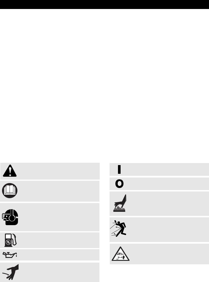
• SAFETY & INTERNATIONAL SYMBOLS •
This operator's manual describes safety and international symbols and pictographs that may appear on this product. Read the operator's manual for complete safety, assembly, operating and maintenance and repair information.
SYMBOL MEANING
•SAFETY ALERT SYMBOL
Indicates danger, warning or caution. May be used in conjunction with other symbols or pictographs.
•WARNING - READ OPERATOR'S MANUAL
Read the operator’s manual(s) and follow all warnings and safety instructions. Failure to do so can result in serious injury to the operator and/or bystanders.
•WEAR EYE AND HEARING PROTECTION
WARNING: Thrown objects and loud noise can cause severe eye injury and hearing loss. Wear eye protection meeting ANSI Z87.1 standards and ear protection when operating this unit. Use a full face shield when needed.
• UNLEADED FUEL
Always use clean, fresh unleaded fuel
• OIL
Refer to operator’s manual for the proper type of oil.
• SHARP BLADE
WARNING: Sharp blade on cutting attachment shield. To prevent serious injury, do not touch the line cutting blade.
SYMBOL MEANING
•ON/OFF STOP CONTROL
ON / START / RUN
•ON/OFF STOP CONTROL
OFF or STOP
•HOT SURFACE WARNING
Do not touch a hot muffler, gear housing or cylinder. You may get burned. These parts get extremely hot from operation. They remain hot for a short time after the unit is turned off.
• THROWN OBJECTS AND ROTATING CUTTER CAN CAUSE SEVERE INJURY
WARNING: Do not operate without the cutting attach-ment shield in place. Keep away from the rotating cutting attachment.
• KEEP BYSTANDERS AWAY
WARNING: Keep all bystanders, especially children and pets, at least 50 feet (15 m) from the operating area.
3

WARRANTY STATEMENT
CRAFTSMAN TWO-YEAR LIMITED WARRANTY
If this Craftsman product fails due to a defect in material or workmanship within two years from the date of purchase, return it to any Sears store, Sears Service Center, or other Craftsman outlet in the United States for free repair. This warranty does not include:
•Expendable items which can wear out from normal use within the warranty period, such as cutting line, air cleaner or spark plug.
•Repairs necessary because of operator abuse or negligence and the failure to operate or maintain the equipment according to all supplied instructions.
This warranty applies for only 90 days if this product is ever used for commercial or rental purposes. This warranty applies only while this product is used in the United States. This warranty gives you specific legal rights, and you may also have other rights which vary from state to state.
Sears, Roebuck and Co., Hoffman Estates, IL 60179
Owner’s Warranty Responsibilities
•As the small off-road engine owner, you are responsible for the performance of the required maintenance listed in your operator’s manual. Sears recommends that you retain all receipts covering maintenance on your small off-road engine, but Sears cannot deny warranty solely for the lack of receipts or for your failure to ensure the performance of all scheduled maintenance.
•As the small off-road engine owner, you should however be aware that Sears may deny you warranty coverage if your small off-road engine or a part has failed due to abuse, neglect, improper maintenance or unapproved modifications.
•You are responsible for presenting your small off-road engine to a Sears authorized service center as soon as problem exists. The warranty repairs should be completed in a reasonable amount of time, not to exceed 30 days.
If you have any questions regarding your warranty rights and responsibilities, you should call 1-800-4-MY-HOME®.
Manufacturer’s Warranty Coverage
•The warranty period begins on the date the engine or equipment is delivered to the retail purchaser.
•The manufacturer warrants to the initial owner and each subsequent purchaser, that the engine is free from defects in material and workmanship which cause the failure of a warranted part for a period of two years.
•Repair and replacement of warranted part will be performed at no charge to the owner at an authorized Sears service center. For the nearest location please contact Sears at: 1-800-4-MY-HOME®.
•Any warranted part which is not scheduled for replacement, as required maintenance or which is scheduled only for regular inspection to the effect of “Repair or Replace as Necessary” is warranted for the period. Any warranted part which is scheduled for replacement as required maintenance will be warranted for the period of time up to the first scheduled replacement point for that part.
•The owner will not be charged for diagnostic labor which leads to the determination that a warranted part is defective if the diagnostic work is performed at an authorized Sears Service Center.
•The manufacturer is liable for damages to other engine components caused by the failure of a warranted part still under warranty.
•Failures caused by abuse, neglect or improper maintenance are not covered under warranty.
•The use of add-on or modified parts can be grounds for disallowing a warranty claim. The manufacturer is not liable to cover failures of warranted parts caused by the use of add-on or modified parts.
•In order to file a claim, go to your nearest authorized Sears Service Center. Warranty service or repairs will be provided at all authorized Sears Service Centers.
•Any manufacturer approved replacement part may be used in the performance of any warranty maintenance or repair of emission related parts and will be provided without charge to the owner. Any replacement part that is equivalent in performance or durability may be used in non-warranty maintenance or repair and will not reduce the warranty obligations of the manufacturer.
•The following components are included in the emission related warranty: engine, air filter, carburetor, primer, fuel lines, fuel pick up/fuel filter, ignition module, spark plug and muffler.
4
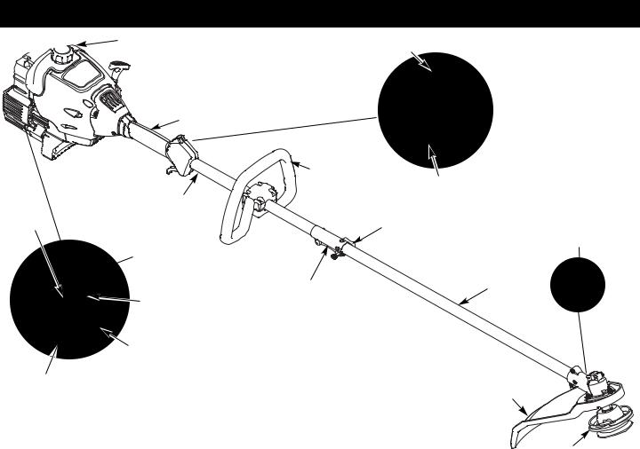
KNOW YOUR UNIT
Fuel Cap |
On/Off Stop Control |
 Starter Rope
Grip
Shaft Grip
|
|
D-Handle |
|
|
|
Throttle Control |
|
Primer |
Shoulder Strap |
|
|
Loop |
|
||
Bulb |
Knob |
||
|
Line Cutting
Blade
EZ Fire™
Lever
Shaft Housing
Convertible™
Air Filter/Muffler Coupler
Cover
Muffler
Cutting
Spark Plug Attachment
Shield
APPLICATIONS
As a trimmer:
•Cutting grass and light weeds.
•Edging
•Decorative trimming around trees, fences, etc. Other optional accessories may be used with this unit.
Hassle Free IV®
Cutting Attachment
5
OIL & FUEL INFORMATION
OIL AND FUEL MIXING INSTRUCTIONS
Old and/or improperly mixed fuel are the main reasons for the unit not running properly. Be sure to use fresh, clean unleaded fuel. Follow the instructions carefully for the proper fuel/oil mixture.
Definition of Blended Fuels
Today's fuels are often a blend of gasoline and oxygenates such as ethanol, methanol, or MTBE (ether). Alcohol-blended fuel absorbs water. As little as 1% water in the fuel can make fuel and oil separate. It forms acids when stored. When using alcohol-blended fuel, use fresh fuel (less than 60 days old).
Using Blended Fuels
If you choose to use a blended fuel, or its use is unavoidable, follow recommended precautions:
•Always use the fresh fuel mix explained in your operator's manual
•Always agitate the fuel mix before fueling the unit
•Drain the tank and run the engine dry before storing the unit
Using Fuel Additives
The bottle of 2-cycle oil that came with your unit contains a fuel additive which will help inhibit corrosion and minimize the formation of gum deposits. It is recommended that you use our 2- cycle oil with this unit. If unavailable, use a good 2-cycle oil designed for air-cooled engines along with a fuel additive, such as STA-BIL® Gas Stabilizer or an equivalent. Add 0.8 oz. (23 ml.) of fuel additive per gallon of fuel according to the instructions on the container. NEVER add fuel additives directly to the unit's fuel tank.
CAUTION: For proper engine operation and maximum reliability, pay strict attention to the oil and fuel mixing instructions on the 2-cycle oil container. Using improperly mixed fuel can severely damage the engine.
Thoroughly mix the proper ratio of 2-cycle engine oil with unleaded gasoline in a separate fuel can. Use a 40:1 fuel/oil ratio. Do not mix them directly in the engine fuel tank. See the table below for specific gas and oil mixing ratios.
NOTE: One gallon (3.8 liters) of unleaded gasoline mixed
 +
+ 
UNLEADED GAS |
2-CYCLE OIL |
|
|
UNLEADED GAS |
2 CYCLE OIL |
1 GALLON US |
3.2 FL. OZ. |
(3.8 LITERS) |
(95 ml) |
1 LITER |
25 ml |
MIXING RATIO - 40:1
with one 3.2 oz. (95 ml.) bottle of 2-cycle oil makes a 40:1 fuel/oil ratio.
NOTE: Dispose of the old fuel/oil mix in accordance to Federal, State and Local regulations.
WARNING: Gasoline is extremely flammable. Ignited vapors may explode. Always stop the engine and allow it to cool before filling the fuel tank. Do not smoke while filling the tank. Keep sparks and open flames at a distance from the area.
WARNING: Remove fuel cap slowly to avoid injury from fuel spray. Never operate the unit without the fuel cap securely in place.
WARNING: Add fuel in a clean, well ventilated outdoor area. Wipe up any spilled fuel immediately. Avoid creating a source of ignition for spilt fuel. Do not start the engine until fuel vapors dissipate.
ASSEMBLY INSTRUCTIONS
INSTALL AND ADJUST THE D-HANDLE
Install
1.Place D-handle the over the shaft housing and onto the bottom clamp (Fig. 1). Place it a minimum of 6 inches (15.24 cm) from the end of the shaft grip.
On/Off Stop Control |
(4) Screws |
Shaft
Housing
Shaft Grip
Minimum 6 Inches
(15.24 cm)
D-Handle 
Bottom Clamp
Fig. 1
INSTALL LINE TRIMMER
ATTACHMENT NOTE: To make installation easier, place the unit on the ground or
on a workbench. 1. Turn knob counterclockwise to
loosen coupler (Fig. 11, p. 8). 2. While firmly holding attachment,
push it straight into the coupler until the release button snaps into
the primary hole (Fig. 12, p. 8). NOTE: Aligning the release button
with the guide recess (Fig. 12, p.
8) will help installation.
Fig. 2
3.Turn the knob clockwise to tighten (Fig. 13, p. 8).
LINE TRIMMER APPLICATIONS
Cutting grass and light weeds; edging; and decorative trimming
2. Start screws with a flat-head or T-25 Torx screwdriver. Do not |
around trees, fences, etc. |
tighten until handle is adjusted. |
|
Adjust
3.While holding the unit in the operating position (Fig. 2), position the D-handle to the location that provides you the best grip.
4.Tighten the clamp screws evenly until the D-handle is secure.
6
STARTING/STOPPING INSTRUCTIONS
WARNING: Operate this unit only in a wellventilated outdoor area. Carbon monoxide exhaust fumes can be lethal in a confined area.
WARNING: Avoid accidental starting. Make sure you are in the starting position when pulling the starter rope (Fig. 5). To avoid serious injury, the operator and unit must be in a stable position while starting.
STARTING INSTRUCTIONS
1.Mix gas with oil.
2.Fill the fuel tank with the fuel/oil mixture. See Oil
and Fuel Mixing Instructions.
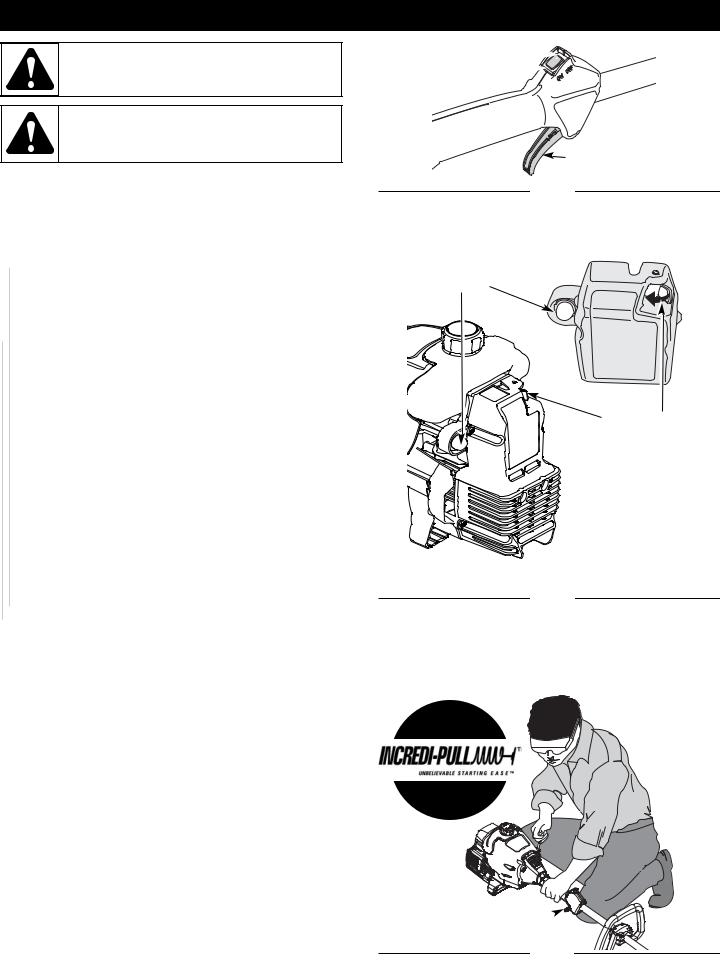
NOTE: There is no need to turn the unit on. The On/Off Stop Control is in the ON ( I ) position at all times (Fig. 3).

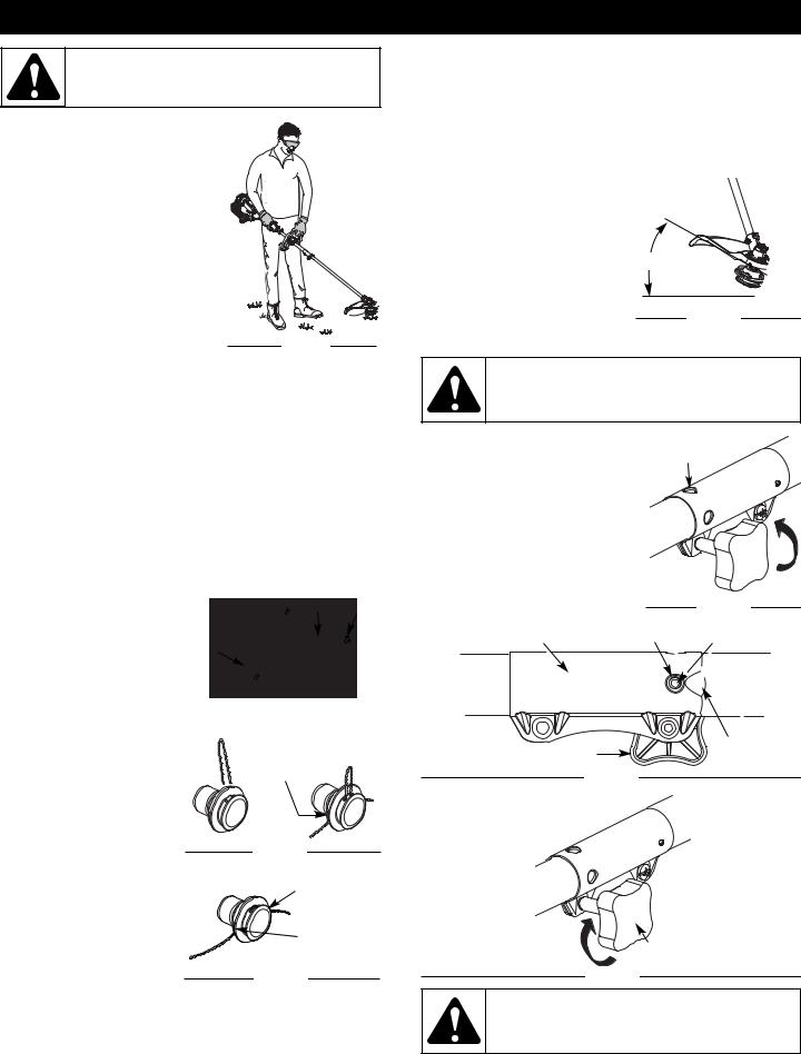
 3. Fully press and release the primer bulb 10 times, slowly. Some amount of fuel should be visible in the primer bulb and fuel lines (Fig. 4). If you can’t see fuel in the bulb, press and release the bulb as many times as it takes before you can see fuel in it.

 4. Push the red EZ-Fire™ lever towards the primer bulb until it clicks and locks into place (Fig. 4).
5.Crouch in the starting position and do not squeeze the throttle control (Fig. 5). Pull the starter rope out with a controlled and steady motion up to 10 times. Repeat until the engine starts.
NOTE: The unit uses the INCREDI-PULL™ starting system , which significantly reduces the effort required to start the engine. You must pull the starter rope out far enough to hear the engine attempt to start. There is no need to pull the rope briskly-- there is no harsh resistance when pulling. Be aware that this starting method is vastly different from (and much easier than) what you may be used to.
6.When the engine starts, squeeze the throttle control for 15 to 30 seconds. This will warm up the unit.
The red EZ-Fire™ lever will click off automatically when you squeeze the throttle control.

 IF... The engine does not start, go back to step 3.


 IF... The engine stops while you are squeezing the throttle, go back to step 4.
Stop/Off (O) 
Start/On ( I )

Throttle Control
Fig. 3
Primer
Bulb
Red EZ-Fire™
Lever
Fig. 4
IF... The engine stops before you squeeze the throttle control, hold the throttle control and pull the starter rope until the trimmer starts.
NOTE: If you are having trouble starting the unit or are operating in extreme temperatures (below 40º F, above 90º F), refer to the Troubleshooting section.
STOPPING INSTRUCTIONS
1.Release your hand from the throttle control. engine to cool down by idling.
2.Press and hold On/Off Stop Control in the OFF until engine comes to a complete stop (Fig. 3).
Trimmer
Equipped With
Incredi-Pull
Starting
Starting
Position
Throttle Control 
Fig. 5
7
OPERATING INSTRUCTIONS
WARNING: Always wear eye, hearing, foot and body protection to reduce the risk of injury when operating this unit.
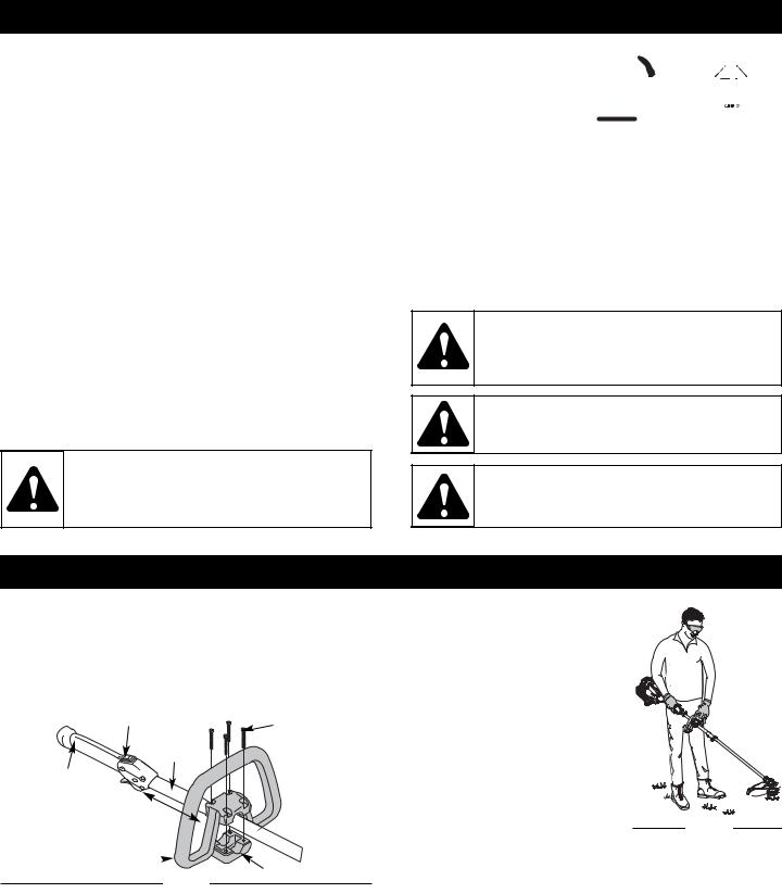
HOLDING THE TRIMMER
Before operating the unit, stand in the operating position (Fig. 6). Check for the following:
• The operator is wearing eye protection and proper clothing
• With a slightly-bent right arm, the operator’s hand is holding the shaft grip
•The operator’s left arm is slightly bent, the left hand holding the D-
handle
• The unit is at waist level
• The cutting attachment is parallel to |
|
|
the ground and easily contacts the |
Fig. 6 |
|
grass without the need to bend over |
||
|
TIPS FOR BEST TRIMMING RESULTS
•Keep the cutting attachment parallel to the ground.
•Cut from left to right whenever possible. Cutting to the right improves the unit's cutting efficiency. Clippings are thrown away from the operator.
•Trim only when grass and weeds are dry.
•The life of your cutting line is dependent upon:
-Following the trimming tips
-What vegetation is being cut
-Where vegetation is being cut
DECORATIVE TRIMMING
Decorative trimming is |
|
|
accomplished by removing all |
30º |
|
vegetation around trees, posts, |
||
fences and more. Rotate the |
|
|
whole unit so that the cutting |
|
|
attachment is at a 30° angle to the |
Fig. 10 |
|
ground (Fig. 10). |
||
|
USING THE CONVERTIBLE™ COUPLER
LINE REPLACEMENT
for Hassle-Free™ Cutting Head
Always use Craftsman Hassle-Free™ XTRA QUIET Spiral Line. Choose the line size best suited for the job at hand. Red colored line is designed for cutting grass and small weeds. Black colored line is designed for cutting larger weeds and light brush.
NOTE: Before inserting new line into the holes in the cutting head, identify the proper holes. Follow directions as shown on the line glide plate. Do Not attempt to remove the cutting head from the unit when replacing line.
1.Remove the old line and line glide plate from the cutting head.
2.Clean entire surface of cutting head. Note positions “A” and “B” on the cutting head.
3.Reinstall line glide plate (Fig.
7). Align arrow with: |
Cutting |
Line Glide |
|||
“A” when using medium (red) or |
Head |
Plate Arrow |
|||
large (black) line, or |
|
|
|
|
|
“B” when using lines with |
|
|
|
|
|
diameters smaller than |
|
|
|
|
|
|
|
|
|
|
|
medium (red) line |
|
|
|
|
|
NOTE: Line glide plate must be |
|
|
|
|
|
reinstalled in cutting head |
|
|
|
|
|
before inserting new line. |
|
|
Fig. 7 |
|
|
|
|
|
|||
4.Insert both ends of your line through the proper
holes in the side of the |
Positioning |
cutting head (Fig. 8). |
Tunnel |
5. Pull the line and make |
|
sure the line is against the hub and is fully extended through the positioning tunnels (Fig. 9).
6. Correctly installed line will |
Fig. 8 |
|
|
||
be the same length on |
Line against |
|
both sides. |
||
NOTE: Do not rest the |
the hub |
|
Hassle-Free™ Cutting |
|
|
Head on the ground |
Positioning |
|
while the unit is running. |
||
Tunnel |
||
Some line breakage will occur |
||
Fig. 9 |
||
from: |
•Entanglement with foreign matter
•Normal line fatigue
•Attempting to cut thick, stalky weeds
•Forcing the line into objects such as walls or fence posts
WARNING: Before you begin using any attachment, read and understand the manual that came with the add-on. Follow all safety information contained within.
You can convert this unit to edge grass.
1.Make sure the unit is turned completely off.
2.Turn the knob counterclockwise to loosen coupler (Fig. 11).
3.Push in the release button (Fig. 12) and twist the shaft 90° until the release button snaps into the 90° hole (Fig. 11).
4.Turn the knob clockwise to lock the coupler (Fig. 13).
90˚ Edging Hole
(Trimmer Only)
Coupler
Knob 
Fig. 11
Convertible™ Coupler Primary Hole Release Button
Knob |
Guide |
|
Recess |
||
|
||
Fig. 12 |
|
|
|
Upper Shaft |
|
|
Housing |
Attachment
Housing
Knob
Fig. 13
CAUTION: Before operating this unit, be sure that the release button is fully snapped into the primary hole (Fig. 12), and that the knob (Fig. 13) is securely tightened.
8
OPERATING INSTRUCTIONS
Craftsman Convertible™ Feature
The coupler allows you to convert this unit for use with the following add-on attachments:
•Cultivator
•Blade Edger
•Blower
•Brush Cutter
•Pruner
WARNING: To avoid serious personal injury and damage to the unit, shut the unit off before removing or installing add-ons.
To Install Attachments
NOTE: To make installation easier, place the unit on the ground or on a workbench.
1.Make sure the unit is turned completely off.
2.Turn the knob counterclockwise to loosen the coupler (Fig. 11).
3.While firmly holding the add-on, push it straight into the coupler until the release button (Fig. 12) snaps into the primary hole (Fig. 12). The primary hole is on the opposite side of the coupler from the knob (Fig. 12). Align the release button with the Guide Recess (Fig. 12) to help installation.
4.Turn the knob clockwise to tighten (Fig. 13).
CAUTION: These add-on attachments are to be snapped into the primary hole only. Using the wrong hole could lead to personal injury or damage to the unit.
To Remove Attachments
1.Make sure the unit is turned completely off.
2.Turn the knob counterclockwise to loosen the coupler (Fig. 11).
3.Press and hold the release button (Fig. 12).
4.While firmly holding the upper shaft housing (Fig. 13), pull the attachment out of the coupler.
MAINTENANCE & REPAIR INSTRUCTIONS
MAINTENANCE SCHEDULE |
AIR FILTER MAINTENANCE |
WARNING: To prevent serious injury, never perform maintenance or repairs with unit running. Always service and repair a cool unit. Disconnect the spark plug wire to ensure that the unit cannot start.
Perform these required maintenance procedures at the frequency stated in the table. These procedures should also be a part of any seasonal tune-up.
NOTE: Some maintenance procedures may require special tools or skills. If you are unsure about these procedures take your unit to any non-road engine repair establishment, individual or authorized service dealer. Call 1-800-4-MY-HOME® for more information.
NOTE: Maintenance, replacement, or repair of the emission control devices and system may be performed by a Sears or other qualified service dealer. Call 1-800-4-MY-HOME® for more information.
In order to assure peak performance of your engine, inspection of the engine exhaust port may be necessary after 50 hours of operation. If you notice lost RPM, poor performance or general lack of acceleration, this service may be required. If you feel your engine is in need of this inspection, refer service to a Sears or other qualified service dealer. Call 1-800-4-MY-HOME® for more information. DO NOT attempt to perform this process yourself as engine damage may result from contaminants involved in the cleaning process for the port.
FREQUENCY |
MAINTENANCE REQUIRED |
SEE |
|
|
|
|
|
Before starting |
Fill fuel tank with fresh fuel |
p. 6 |
|
engine |
|||
|
|
||
|
|
|
|
Every 10 hours |
Clean and re-oil air filter |
p. 9 & 10 |
|
|
|
|
|
Every 25 hours |
Check and clean spark arrestor |
p. 10 |
|
Check spark plug condition and gap |
p. 11 |
||
|
|||
|
|
|
|
|
Inspect exhaust port and spark |
|
|
Every 50 hours |
arrestor screen for clogging or |
p. 10 |
|
|
obstruction |
|
|
|
|
|
WARNING: To avoid serious personal injury, always turn your unit off and allow it to cool before you clean or service it.
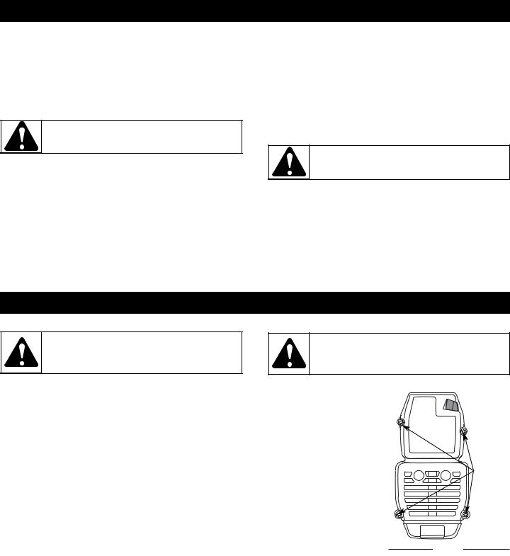
Removing the Air Filter/Muffler Cover
1. Remove the four (4) screws securing the air filter/muffler cover (Fig. 14). Use a flat
blade or T20 Torx bit screwdriver.
2. Pull the cover from the
engine. Do not force. |
|
|
Cleaning the Air Filter |
Screws |
|
Failure to maintain your air filter |
||
|
||
properly can result in poor |
|
|
performance or can cause |
|
|
permanent damage to your |
|
|
engine. |
|
|
1. Remove air filter/muffler |
|
|
cover. Refer to Removing |
|
|
the Air Filter/Muffler Cover |
Fig. 14 |
|
above. |
||
|
2.Turn cover over and look inside to locate the air filter. Remove the air filter from inside the air filter/muffler cover (Fig. 15).
3.Wash the filter in detergent and water (Fig. 16). Rinse the filter thoroughly. Squeeze out excess water. Allow it to dry completely.
4.Apply enough clean SAE 30 oil to lightly coat the filter (Fig. 17).
5.Squeeze the filter to spread and remove excess oil (Fig. 18).
9

MAINTENANCE & REPAIR INSTRUCTIONS
Air Filter
Inside Muffler
Cover
Fig. 15 |
|
|
|
Fig. 16 |
|
|
|
||
|
|
|
|
|
Fig. 17 |
|
|
|
Fig. 18 |
|
|
|
||
|
|
|
|
|
6. Replace the air filter inside the air filter/muffler cover (Fig. 15).
NOTE: Operating the unit without the air filter and air filter/muffler cover assembly will VOID the warranty.
Reinstalling the Air Filter/Muffler Cover
1.Place the air filter/muffler cover over the back of the carburetor and muffler. Align the screw holes.
2.Insert the four (4) screws into the holes in the air filter/muffler cover (Fig. 14) and tighten. Do not over tighten.
SPARK ARRESTOR MAINTENANCE
NOTE: Pay close attention when disassembling the muffler so you can put it back together correctly. Failure to do so will damage the unit and may cause serious personal injury.
1.Remove air filter/muffler cover. Refer to Removing the Air Filter/Muffler Cover (p. 9).
2.Locate the muffler, but do not remove it. Find the screw on
the bottom of |
Spark Arrestor Slots |
To Engine |
|
the muffler (Fig. |
|||
19). This screw |
Hood |
|
|
holds the Spark |
|
|
|
Arrestor Hood |
|
|
|
Assembly and |
|
|
|
the spark |
|
|
|
arrestor screen |
|
|
|
to the bottom of |
Screw |
Spark Arrestor |
|
the muffler. |
Muffler |
||
Remove this |
Tabs |
Screen |
|
screw using |
|
Fig. 19 |
|
either a Torx |
|
|
|
T20 or flat blade screwdriver.
3.Using a small flat blade screwdriver, carefully pry up the spark arrestor screen from the recessed hole, taking care to notice that the “raised” part of the spark arrestor screen is inside the recessed hole. Remove the spark arrestor screen from the muffler.
4.Clean the spark arrestor screen with a wire brush. Replace it if it is damaged, or if you are unable to clean it thoroughly.
5.Reinstall the spark arrestor screen by putting the “raised” portion of the screen inside the recessed hole of the muffler. Make sure that the spark arrestor screen fits flat against the muffler.
6.Place the spark arrestor plate on top of the spark arrestor screen with the raised side up and the opening facing toward the engine (Fig. 19)
7.Place the spark arrestor hood on top of the spark arrestor plate with the “raised” side up and the opening facing AWAY from the engine (Fig. 19). Verify that the exhaust will be directed AWAY from the engine.
8.Replace the screw you removed in Step 2 and tighten securely.
9.Reinstall the air filter/muffler cover (Fig. 14).
WARNING: If the spark arrestor hood and spark arrestor screen are not tightened securely, they could fall off causing damage to the unit and possible serious personal injury.
CARBURETOR ADJUSTMENT
The idle speed of the engine is adjustable through the air filter/muffler cover (Fig. 20).
NOTE: Careless adjustments can seriously damage your unit. Contact a Sears or other qualified service dealer to make carburetor adjustments. Call 1-800-4-MY-HOME® for more information.
Idle
Speed
Screw
Fig. 20
Check Fuel Mixture
Old and/or improperly mixed fuel is usually the reason for improper unit performance. Drain and refill the tank with fresh, properly-mixed fuel prior to making any adjustments. Refer to
Oil and Fuel Information (p. 6).
Clean Air Filter
The condition of the air filter is important to the operation of the unit. A dirty air filter will restrict air flow and change the air/fuel mixture. This is often mistaken for an out of adjustment carburetor. Check the condition of the air filter before adjusting the idle speed screw. Refer to Air Filter Maintenance (p. 9).
10
 Loading...