


315.220381
Owner's Manual
CRAFTSMAN
PROFESSIOMAL
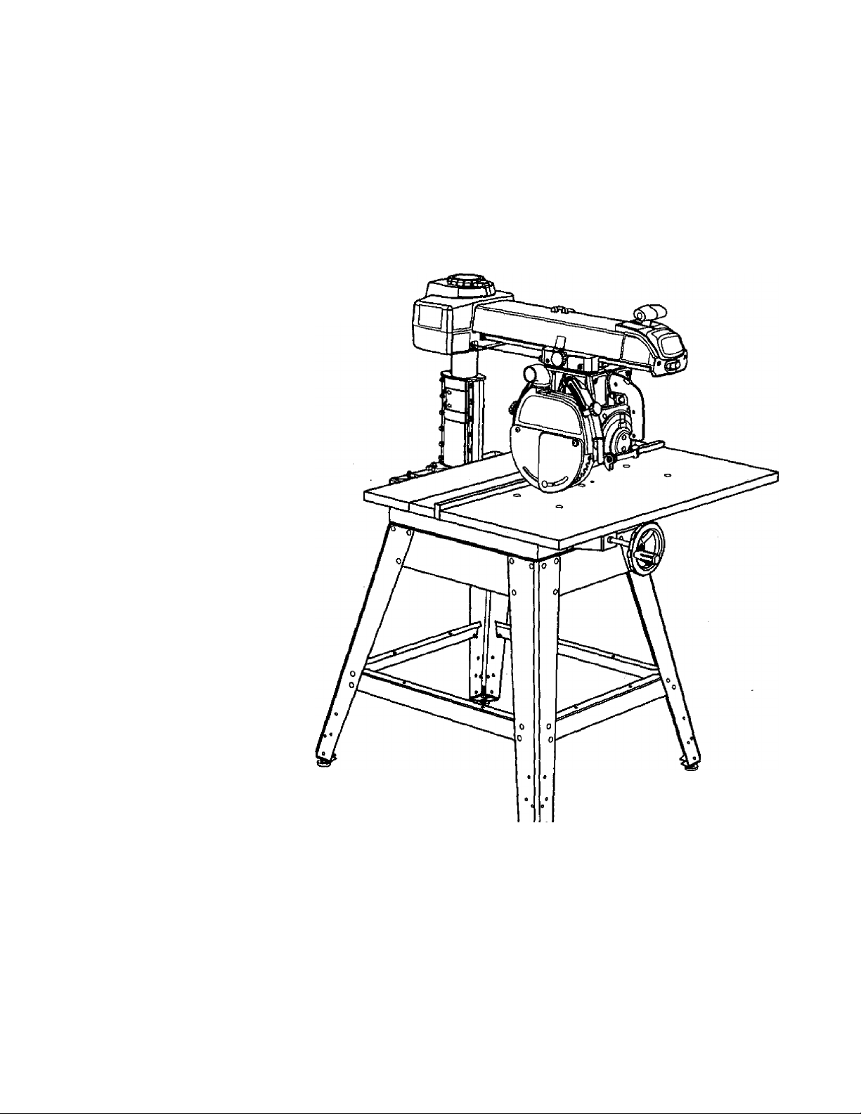
10 in. Stationary
RADIAL ARM SAW
Model No.
315.220381
Save this manual for
future reference.
^ CAUTION: Read and follow all
Safety Rules and Operating
Instructions before first use of this
product.
Customer Help Line: 1-800-932-3188
Sears, Roebuck and Co., Hoffman Estates, IL 60179 USA
Visit the Craftsman web page: www,sears.com/craftsman
972000-705
10-99
• Safety
• Features
• Assembly
• Operation
• Maintenance
• Parts List
WARRANTY
FULL ONE YEAR WARRANTY ON CRAFTSMAN RADIAL ARM SAW
If this CRIlFTSHAN’f^aclial Arm Saw fails due to a defect in material or workmanship within one year from the
date of purchase, Sears will repair it, free of charge.
Contact a Sears Service Center for repair.
If this product is used tor commercial or rental purposes, this warranty applies only lor 90 days from the date of
purchase.
This warranty gives you specific legal rights, and you may also have other rights which vary from state to state.
Sears, Roebuck and Co., Dept. 81 TWA, Hoffman Estates, IL 60179
INTRODUCTION
Your saw has many features for making cutting operations more pleasant and enjoyable. Safety, performance
and dependability have been given lop priority in the design of this saw making it easy to maintain and operate.
A CAUTION: Carefully read through this entire owner's manual before using your new saw. Pay close
“ attention to the Rules For Safe Operation, and all Safety Alert Symbols, including Danger, Warning and
Caution. If you use your saw properly and only for what it is intended, you will enjoy years of safe, reliable
service.
A Look for this symbol to point out important safety precautions. It means attention!!! Your safety is
invoived.
WARNING:
The operation of any power tool can result in foreign objects being thrown into your eyes,
which can result in severe eye damage. Before beginning power tool operation, always wear
safety goggles or safety glasses with side shields and a full face shield when needed. We
recommend Wide Vision Safety Mask for use over eyeglasses or standard safety glasses
with side shields, available at Sears Retail Stores.
TABLE OF CONTENTS
Warranty and Introduction................................................................................................................................................2
Table of Contents............................................................................................................................................................2-3
Rules For Safe Operation...............................................................................................................................................4-7
Electrical..........................................................................................................................................................................8*2
Product Specifications and Glossary.......................................................................................................................10-11
Unpacking and Accessories...........................................................................................................................................11
Loose Parts List........................................................................................................................................................ 12-14
Toots Needed....................................................................................................................................................................15
Labels...........................................................................................................................................................................16* “17
Features.......................................................................................................................................................................18-21
Assembly.....................................................................................................................................................................22-36
Assembling Leg Stand.....................................................................................................................................................22
Mounting Saw to Leg Stand............................................................................................................................................23
CRUFTIMRir RADIAL SAW 315.220381

TABLE OF CONTENTS
Attaching Elevating Handwheel......................................................................................................................................23
Installing the Yoke Assembly.........................................................................................................................................24
Removing the Blade........................................................................................................................................................25
Attaching Table Supports...............................................................................................................................................25
Setting the Arm Lock Knob.............................................................................................................................................26
Setting the Yoke Clamp...................................................................................................................................................26
Setting the Bevel Lock Lever..........................................................................................................................................27
Tightening the Arm and Column.....................................................................................................................................28
Adjusting the Column Tube.......................................................................................................................................28-29
Adjusting the Carriage Bearings....................................................................................................................................30
Leveling the Table Supports..........................................................................................................................................31
Installing the Front Table.............................................................................................................................................. 32
Leveling the Front Table..................................................................................................................................................33
Installing Rear Table, Spacer Table, Fence, and Clamps.......................................................................................33-34
Installing Blade and Blade Guard...................................................................................................................................34
Aligning Riving Knife to Blade........................................................................................................................................35
Installing Rip Scale indicators........................................................................................................................................36
Adjustments................................................................................................................................................................36-42
Aligning the Arm for Cross Cuts......................................................................................................:.............................37
Aligning the Blade to Table at 0* Bevel......................................................................................................................... 38
Squaring Blade to Fence............................................................................................................................................. 39
Paralleling Blade to Table...............................................................................................................................................40
Aligning the Rip Scale Indicators.................................................................................................................................. 41
Installing Control Cut Device..........................................................................................................................................42
Operation................................................................................................................................................................... 43-53
Basic Operation of the Radial Arm Saw........................................................................................................................ 43
Types of Cuts....................................................................................................................................................................43
Switch and Switch Key....................................................................................................................................................44
Causes of Kickback.........................................................................................................................................................44
Avoiding Kickback...........................................................................................................................................................44
Cutting Aids......................................................................................................................................................................45
Making a Cross Cut..........................................................................................................................................................46
Making a Miter Cut...........................................................................................................................................................47
Making a Bevel Cut..........................................................................................................................................................48
Making a Compound Cross Cut.....................................................................................................................................49
Rip Cut Hazards and Precautions..................................................................................................................................50
Setting Up a Rip Cut...................................................................................................................................................50-51
Making a Rip Cut.............................................................................................................................................................51
Making Other Cuts...........................................................................................................................................................52
Cutting Long Workpieces................................................................................................................................................52
Non-Through Cuts...........................................................................................................................................................53
Maintenance.....................................................................................................................................................................54
Troubleshooting..........................................................................................................................................................55-59
Exploded View and Repair Parts List.......................................................................................................................60-81
Parts Ordering / Service.....................................................................................................................................back page
CRRFTSMRr RADIAL SAW 315,220341

RULES FOR SAFE OPERATION
The purpose of safety symbols is to attract your attention to possible dangers. The safety symbols, and
the explanations with them, deserve your careful attention and understanding. The safety warnings do
not by themselves eliminate any danger. The instructions or warnings they give are not substitutes for
proper accident prevention measures.
SYMBOL
A
A
A
A
MEANING
SAFETY ALERT SYMBOL
Indicates danger, warning or caution. May be used in conjunction with other symbols or
pictographs.
DANGER: Faiiure to obey a safety warning will result in serious injury to yourself or to others.
Always follow the safety precautions to reduce the risk of fire, electric shock and personal injury.
WARNING: Failure to obey a safety warning can result in serious injury to yourself or to others.
Always follow the safety precautions to reduce the risk of fire, electric shock and personal injury.
CAUTION: Failure to obey a safety warning may result in property damage or personal injury to
yourself or to others. Always follow the safety precautions to reduce the risk of fire, electric shock
and persona! injury.
Note: Advises you of information or instructions vital to the operation or maintenance of the equipment.
IMPORTANT
Servicing requires extreme care and knowledge of the
system and should be performed only by a qualified
service technician. For service we suggest you contact
your nearest Sears repair center. Always use original
factory replacement parts when servicing.
If you have questions about terms in the following
rules, refer to the Glossary of Terms for Woodworking
or the Features section.
READ ALL INSTRUCTIONS
■ KNOW YOUR POWER TOOL. Read the owner's
manual carefully. Learn the saw's applications and
limitations as well as the specific potential hazards
related to this tool.
■ DO NOT USE IN DANGEROUS ENVIRONMENT.
Do not use power tools near gasoline or other
flammable liquids, in damp or wet locations, or
expose them to rain. Keep the work area well lit.
■ KEEP CHILDREN AND VISITORS AWAY. All
visitors should wear safety glasses and be kept a
safe distance from work area. Do not let visitors
contact the tool or extension cord while operating.
■ KEEP WORK AREA CLEAN. Cluttered work
areas and work benches invite accidents. DO NOT
leave tools or pieces of wood on the saw while it is
in operation. Keep floors clean and free of saw
dust.
■ MAINTAIN TOOLS WITH CARE. Keep tools sharp
and clean for better and safer performance. Follow
Instructions for lubricating and changing accesso
ries.
L WARNING: Do not attempt to operate this tool
* until you have read thoroughly and understand
completely all instructions, safety rules, etc.
contained in this manual. Failure to comply can
result in accidents involving fire, electric shock,
or serious personal injury. Save owner's manual
and review frequently for continuing safe
operation, and instructing others who may use
this tool.
MAKE WORKSHOP CHILD-PROOF with padlocks
and master switches or by removing switch keys.
USE THE RIGHT TOOL FOR THE JOB. Do not
force the tool or attachment to do a job it was not
designed for. Use it only the way it was intended.
DRESS PROPERLY. Do not wear loose clothing,
gloves, neckties, rings, bracelets, or other jewelry.
They can get caught and draw you into moving
parts. Nonslip footwear is recommended. Also
wear protective hair covering to contain long hair.
ALWAYS WEAR SAFETY GLASSES WITH SIDE
SHIELDS. Everyday eyeglasses have only impact-
resistant lenses; they are NOT safety glasses.
NEVER STAND ON TOOL. Serious injury could
occur if the tool is tipped or if the blade is uninten
tionally contacted.
DO NOT OVERREACH. Keep proper footing and
balance at alt times.
SECURE WORK. Use clamps or a vise to hold ■
work when practical. It's safer than using your
hand and frees both hands to operate the tool.
CRRFrSMIltr RADIAL SAW 315.220381

RULES FOR SAFE OPERATION (Continued)
USE THE PROPER EXTENSION CORD. Make
sure your extension cord is in good condition. Use
only a cord heavy enough to carry the current your
product will draw. An undersized cord will cause a
drop in line voltage resulting in loss of power and
overheating. A wire gage size (A.W.G.) of at least
14 is recommended for an extension cord 25 feet
or less in length. If in doubt, use the next heavier
gage. The smaller the gage number, the heavier
the cord.
AVOID ACCIDENTAL STARTING. Be sure switch
is off when plugging in the tool.
REMOVE WRENCHES AND ADJUSTING KEYS.
Get in the habit of checking - before turning on the
tool - that hex keys and adjusting wrenches are
removed from tool.
CHECK DAMAGED PARTS. Before using the tool
again, check any damaged parts, including guards,
for proper operation and performance. Check
alignment of moving parts, binding of moving parts,
breakage of parts, saw stability, mounting, and any
other conditions that may affect its operation. A
damaged part must be properly repaired or re
placed by a qualified service technician at a Sears
repair center to avoid risk of personal injury.
USE ONLY CORRECT BLADES. Use the right
blade style for the material and the type of cut.
Use only blades marked for at least 5,000 rpm and
10 in. or smaller, with a 5/8 in. arbor hole.
KEEP GUARDS IN PLACE and in good working
order. This includes the blade guard, the riving
knife, and the anti-kickback pawls.
CHECK DIRECTION OF FEED. When ripping,
feed work into a blade or cutter against the direc
tion of rotation of the blade or cutter.
NEVER LEAVE TOOL RUNNING UNATTENDED.
TURN THE POWER OFF. Do not leave the tool
until it comes to a complete stop.
USE RECOMMENDED ACCESSORIES. Using
improper accessories may risk injury. Consult the
Accessories section for recommended accesso
ries.
USE ONLY SEARS REPLACEMENT PARTS. All
repairs, whether electrical or mechanical, should
be made by a qualified service technician at a
Sears repair center.
■ DISCONNECT ALL TOOLS. When not in use.
before servicing, or when changing attachments,
blades, bits, cutters, etc., all tools should be
disconnected from the power supply.
■ DO NOT FORCE THE TOOL. It will do the job
better and more safely at the rate for which it was
designed.
■ BEFORE MOUNTING, DISCONNECTING OR
REMOUNTING THE MOTOR; unplug №e saw and
remove the switch key.
A WARNING: When servicing, use only identical
Craftsman replacement parts. Use of any other
parts may create a hazard or damage product.
■ NEVER USE THIS TOOL IN AN EXPLOSIVE
ATMOSPHERE. Normal sparking of the motor
could ignite fumes.
■ MAKE SURE THE WORK AREA HAS AMPLE
LIGHTING to see the work and that no obstruc
tions will interfere with safe operation BEFORE
performing any work using this tool.
■ DO NOT USE TOOL IF SWITCH DOES NOT
TURN IT ON AND OFF. Have defective switches
replaced by a qualified service technician at a
Sears repair center.
■ GUARD AGAINST ELECTRICAL SHOCK by
preventing body contact with grounded surfaces
such as pipes, radiators, ranges, refrigerator
enclosures,
■ GROUND ALL TOOLS. See Electrical page.
■ WEAR A DUST MASK to keep from inhaling fine
particles. Use wood dust collection systems
whenever possible.
■ PROTECT YOUR HEARING. Wear hearing
protection during extended periods of operation.
■ DO NOT OPERATE THIS TOOL WHILE UNDER
THE INFLUENCE OF DRUGS, ALCOHOL, OR
ANY MEDICATION.
■ STAY ALERT AND EXERCISE CONTROL. Watch
what you are doing and use common sense. Do
not operate tool when you are tired. Do not
rush.
■ AVOID AWKWARD OPERATIONS AND HAND
POSITIONS where a sudden slip could cause your
hand to move into the blade. ALWAYS make sure
you have good balance.
CRflFnNflN* RADIAL SAW 315.220381

RULES FOR SAFE OPERATION (Continued)
GUARD AGAINST KICKBACK. Kickback can
occur when the blade stalls, driving the work piece
back toward the operator. It can cause your hand
to contact the blade, resulting in serious personal
injury. Stay out of the blade path and turn switch
off immediately if blade binds or stalls.
DO NOT USE A PERSON AS A SUBSTITUTE
FOR A TABLE if additional support is needed. Use
a support the same height as the table.
USE A SUPPORT FOR THE SIDES AND BACK
OF THE SAW TABLE when sawing wide or long
workpieces to minimize the risk of blade pinching
and kickback. Use a sturdy “outrigger” support to
prevent tipping if a table extension more than 24
inches long is attached to the saw.
CUT ONLY WOOD, PLASTIC OR WOOD-LIKE
MATERIALS. Do not cut metal.
BEFORE MAKING A CUT, be sure all adjustments
are secure.
NEVER cut more than one piece at a time. DO
NOT STACK more than one workpiece on the saw
table at a time.
DO NOT REMOVE THE SAW'S BLADE GUARD.
Never operate the saw with the blade guard
removed. Make sure all guards are operating
properly before each use.
NEVER PERFORM ANY OPERATION FREE
HAND. Always place the workpiece to be cut on
the saw table and position it firmly against the
fence as a backstop.
USE THE RIP FENCE. Always use a fence or
straight edge guide when ripping.
BE SURE THE BLADE PATH IS FREE OF
NAILS. Inspect for and remove all nails from
lumber before cutting.
BE SURE THE BLADE CLEARS THE WORK
PIECE. Never start the saw with the blade touching
the stock.
KEEP HANDS AWAY FROM CUTTING AREA.
Do not reach underneath work or in blade cutting
path with your hands and fingers for any reason.
Always turn the power off when cut is complete.
USE A PUSHBLOCK OR PUSHSTICK in rip mode
for workpieces so small that your fingers go under
the blade guard. NEVER TOUCH BLADE or other
moving parts during use, for any reason.
■ ALLOW THE MOTOR TO COME UP TO FULL
SPEED before starting a cut to avoid blade binding
or stalling.
■ ALWAYS PUSH THE WORKPIECE when ripping;
never pull it toward the saw.
■ DO NOT PEED THE MATERIAL TOO QUICKLY-
Do not force the workpiece against the blade.
■ ALWAYS TURN OFF SAW before disconnecting
it, to avoid accidental starting when reconnecting
to the power supply. NEVER leave the saw
unattended while connected to a power source.
■ BEFORE CHANGING THE SETUP, REMOVING
COVERS, GUARDS, OR BLADE; unplug the saw
and remove the switch key.
■ KEEP TOOL DRY, CLEAN, AND FREE FROM
OIL AND GREASE. Always use a clean cloth
when cleaning. Never use brake fluids, gasoline,
petroleum-based products, or any solvents to
clean tool.
■ KEEP BLADES CLEAN, SHARP AND WITH
SUFFICIENT SET. Sharp blades minimize stalling
and kickback. Keep blades free of rust, grease,
and pitch.
WARNING: Blade coasts after being turned off.
■ USE ONLY OUTDOOR EXTENSION CORDS.
Use only extension cords with the marking “Ac
ceptable for use with outdoor appliances; store
indoors while not in use.” Use extension cords with
an electrical rating not less than the saw's rating.
Always disconnect the extension cord from the
outlet before disconnecting the product from the
extension cord.
■ INSPECT TOOL CORDS AND EXTENSION
CORDS PERIODICALLY and, if damaged, have
repaired by a qualified service technician at a
Sears repair center. Stay constantly aware of cord
location and keep it well away from the moving
blade. ~
■ DO NOT ABUSE CORD. Never yank the cord to
disconnect it from receptacle. Keep the cord from
heat, oil, and sharp edges.
■ SAVE THESE INSTRUCTIONS. Refer to them
frequently and use to instruct other users. If you
loan someone this tool, loan them these instruc
tions also.
SAVE THESE INSTRUCTIONS
CRRFTSNRir RADIAL SAW 315.220381

ADDITIONAL SAFETY RULES FOR RADIAL SAWS
■ SECURE THE SAW. Firmly bolt the saw to the leg
stand to keep the saw from tipping, walking, or
sliding.
■ DO NOT SET UP WORK WITH THE BLADE
SPINNING. Keep the saw power off until you are
ready to use it.
■ RIP ONLY WORKPIECES LONGER THAN THE
BLADE’S DIAMETER. Never rip a piece of wood
that is shorter than the diameter of the blade.
■ NEVER LOWER AN UNLOCKED REVOLVING
CUTTING TOOL. Always lock the carriage lock
knob before lowering the blade.
■ SHUT OFF THE POWER TO FREE A JAMMED
GUARD. Press the switch off before putting your
hands near the blade. Wait for the blade to stop,
then free the guard.
■ LOCK THE SAW BEFORE MOVING IT. Secure
the radial arm with the arm lock knob. Secure the
carriage with the carriage lock knob.
■ POSITION THE WORKPIECE WITH THE FIN
ISHED SIDE DOWN. If the anti-kickback pawls
catch the wood to stop kickback, they could mar
the top surface or cause splintering.
■ POSITION THE WORKPIECE SO NO ONE MUST
STAND IN LINE WITH THE BLADE. If kickback or
climb occurs, a helper, operator, or observer in the
sawblade path could be seriously injured.
■ POSITION THE CUT SO THE WASTE PART
FALLS OFF. Never use a length stop on the free
end of the workpiece. Never apply force to the free
end or hold it while the sawblade is rotating.
WARNING: In a rip cut, holding the cut-off edge
behind the blade can cause the cut edges to
pinch, risking kickback. It could cause the blade
to climb over the front edge of the wood and
contact your hand.
■ BEFORE STARTING EACH CUT, check that no
play exists in the carriage. Be sure the arm, yoke
and bevel locks and clamps are tight. Verify the
blade, all handles, blade washers, and blade nuts
are secure.
■ BEFORE MAKING A CUT, test the upper and
lower blade guards for free movement up and
down. Position the nose of the guard to just clear
the workpiece.
■ AVOID KICKBACK AND POSSIBLE INJURY by
preventing heeling, grabbing, and pinching.
■ BEFORE CUTTING, position and tighten the blade
guard and anti-kickback pawls. Test the pawls to
make sure they would stop kickback if it started.
Keep the points sharp.
■ KEEP THE SAW BLADE PATH CLEAR. Position
the saw to allow enough room on all sides so
neither the operator nor a visitor stands in line with
the sawblade.
■ AVOID HEELING by adjusting the saw blade so it
exactly parallels the fence during ripping opera
tions.
■ AVOID GRABBING in rip mode by keeping the
saw blade correctly adjusted and by feeding the
work from the infeed side (opposite the anti
kickback pawls).
■ AVOID PINCHING by using a riving knife and
sharp saw blade. Keep the work positioned firmly
against the fence.
■ USE IN-RIP WHENEVER POSSIBLE by position
ing the work so the blade is between (inside) the
column and the motor.
■ NEVER ADJUST GUARD, PAWLS, OR BLADE
WITHOUT DISCONNECTING THE POWER.
Always turn off the switch and unplug the cord
before freeing a jammed blade, tightening a loose
blade, or repositioning the guard or pawls.
A CAUTION: Do not turn the motor switch on and
off rapidly. This can loosen the sawblade.
■ NEVER CUT MORE THAN ONE PIECE OF
WOOD AT A TIME. The feed will be uneven and
could cause the blade to pick up one or more
pieces and cause serious injury.
■ TURN OFF SAW IF A STRANGE NOISE OR
HEAVY VIBRATION OCCURS. Immediately turn
off the saw, locate the source, and correct the
problem before using the saw further.
■ POSITION THE CUT SO THE BLADE WILL NOT
EXTEND BEYOND THE EDGE OF THE TABLE.
■ KEEP THE GUARDS IN PLACE AND THE WORK
SURFACE CLEAR DURING A CUT. Small objects
or wood slivers can ricochet from the blade into the
fence and back toward the operator. If the blade
loosens slivers, remove them with a stick, not your
hand.
■ IN A RIP CUT, DO NOT LET GO OF THE WORK
PIECE UNTIL THE CUT IS COMPLETE. When the
workpiece is fed into the blade, push the workpiece
all the way past the blade.
CRAFTSMAN* RADIAL SAW 315.220361
ELECTRICAL
EXTENSION CORDS
Use only 3-wire extension cords that have 3-prong
grounding plugs and 3-pole receptacles that accept
the tool's plug. When using a power tool at a consider
able distance from the power source, use an exten
sion cord heavy enough to carry the current that the
tool will draw. An undersized extension cord will
cause a drop in line voltage, resulting in a loss of
power and causing the motor to overheat. Use the
chart provided below to determine the minimum wire
size required in an extension cord. Only round jack
eted cords listed by Underwriter's Laboratories (UL)
should be used.
Length of Extension Cord Wire Size (A.W.G.)
Up to 25 feet 14
26-100 feet 12
When working with the too! outdoors, use an exten
sion cord that is designed for outside use. This is
indicated by the letters WA on the cord's jacket.
Before using an extension cord, inspect it for loose or
exposed wires and cut or worn insulation.
CAUTION: Keep the cord away from the cutting
area and position the cord so that it will not be
caught on lumber, tools, or other objects during
cutting operations.
ELECTRICAL CONNECTION
Your Sears Craftsman Radial Arm Saw is powered by
a precision built electric motor. It should be connected
to a power supply that is 120 volts, 60 Hz, AC only
{normal household current). It should be connected
to a 240 volt power supply only if it has been reset
according to the instructions in this manual. The
motor has been set at the factory for 120 volts; if it is
reconnected to operate at 240 volts, the main power
cord plug and any receptacle must be replaced with
devices rated for 240 volts. This tool will not operate
on direct current (DC). A substantial voltage drop will
cause a loss of power and the motor will overheat. If
the saw does not operate when plugged into an outlet,
double check the power supply.
SPEED AND WIRING
The no-load speed of your saw is approximately 3,600
rpm. This speed is not constant. For voltage, the
wiring in a shop is as important as the motor's horse
power rating. A line intended only for lights cannot
properly carry a power tool motor. Wire that is heavy
enough for a short distance will be too light for a
greater distance. A line that can support one power
tool may not be able to support two or three tools.
GROUNDING INSTRUCTIONS
In the event of a malfunction or breakdown, grounding
provides a path of least resistance for electric current
to reduce the risk of electric shock. This toot is
equipped with an electric cord having an equipment
grounding conductor and a grounding plug. The plug
must be plugged into a matching outlet that is properly
installed and grounded in accordance with all local
codes and ordinances.
Do not modify the plug provided. If it will not fit the
outlet, have the proper outlet installed by a qualified
electrician. Improper connection of the equipment
grounding conductor can result in a risk of electric
shock. The conductor with insulation having an outer
surface that is green with or without yellow stripes is
the equipment-grounding conductor. If repair or
replacement of the electric cord or plug is necessary,
do not connect the equipment-grounding conductor to
a live terminal.
Check with a qualified electrician or service personnel
if the grounding instructions are not completely
understood, or if in doubt as to whether the tool is
properly grounded.
Repair or replace a damaged or worn cord immedi
ately.
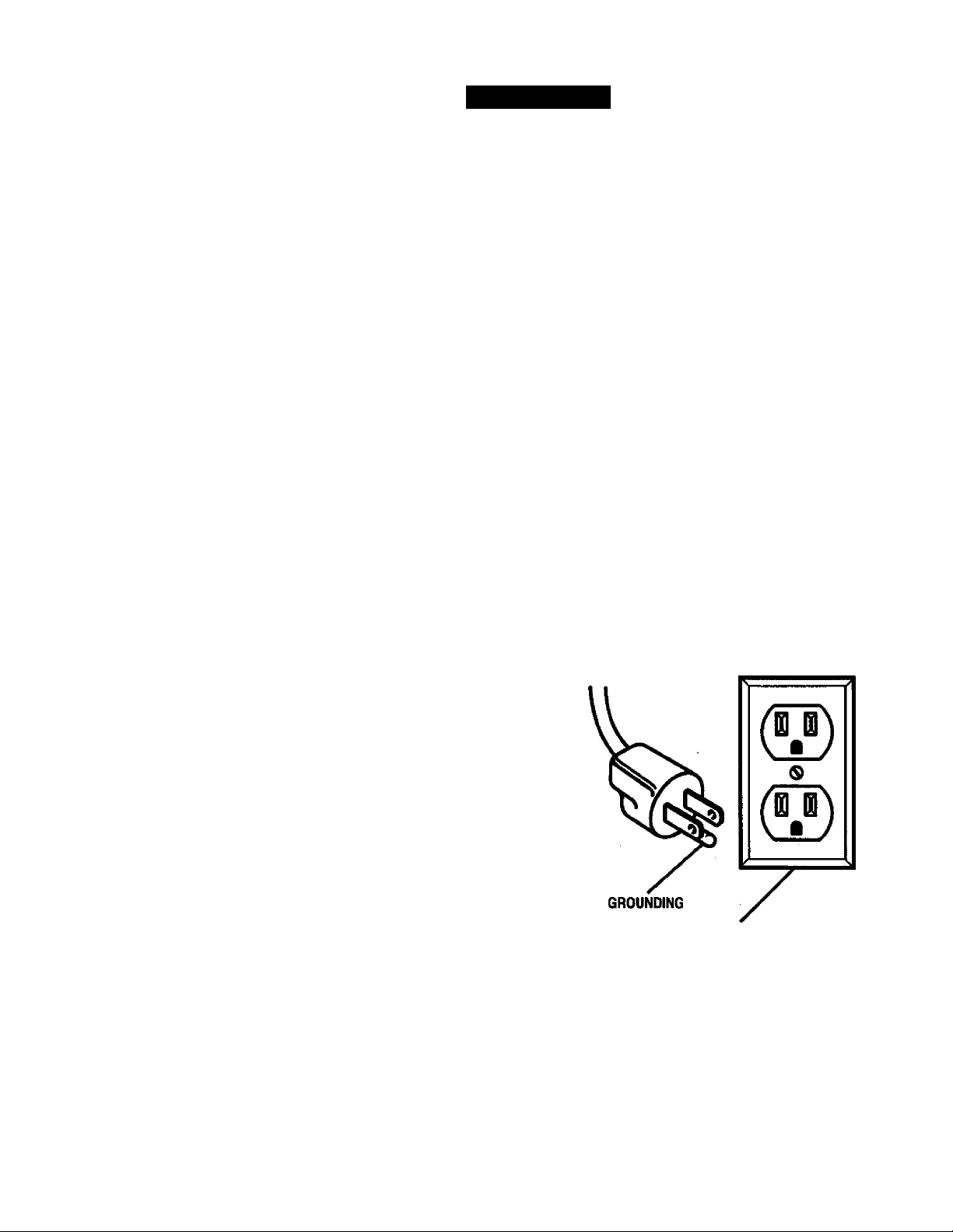
This tool is intended for use on a circuit that has an
outlet like the one shown in Figure 1. It also has a
grounding pin like the one shown.
PIN
COVER OF GROUNDED
OUTLET BOX Fig, 1
CRAFTSMiir RADIAL SAW 315.220361
ELECTRICAL
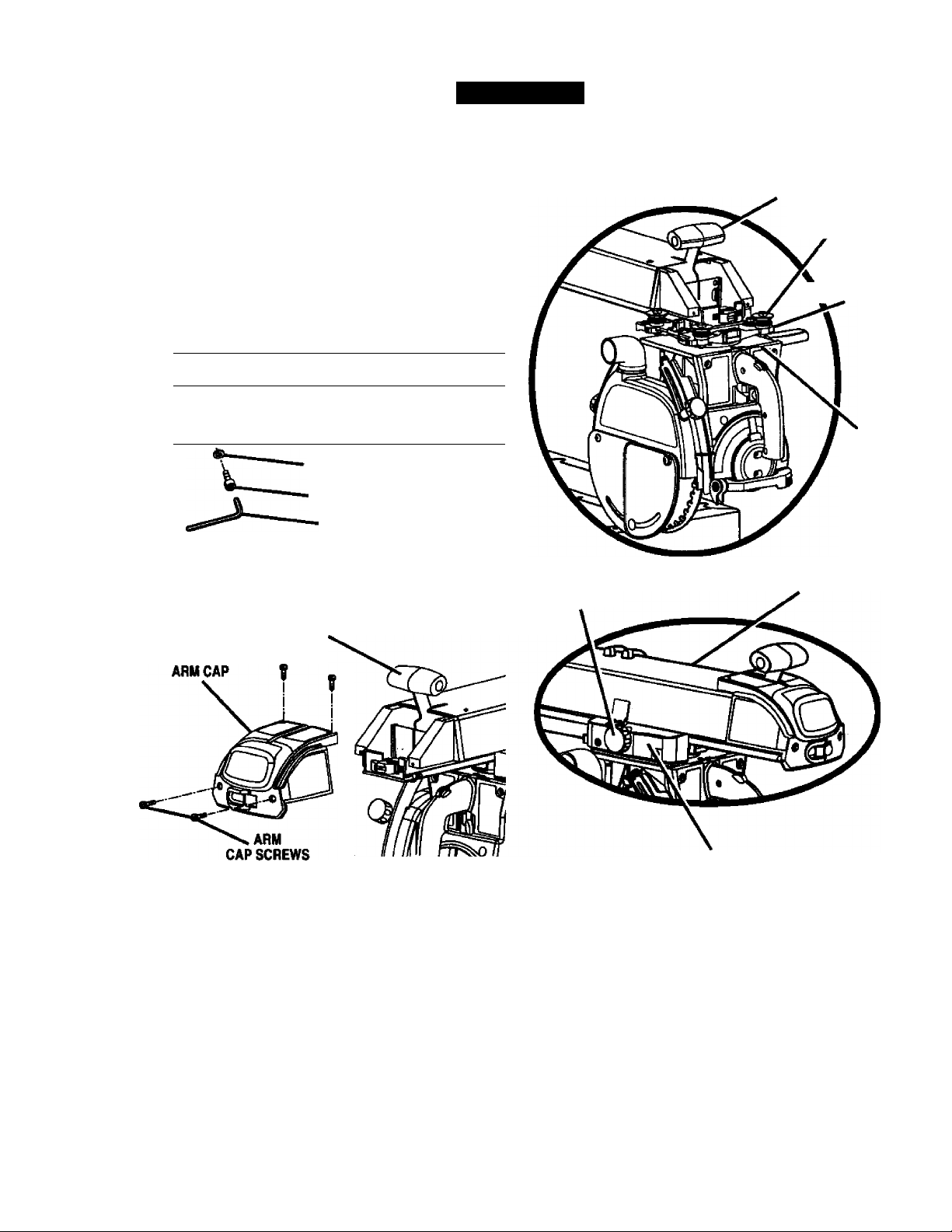
CHANGING VOLTAGE
See Figures 2-4.
Your radial saw has been set up at the factory to
operate efficiently on a 120V AC single voltage circuit.
However, if heavy duty operation is required, the
circuits are overloaded, or the circuit is low voltage,
have a qualified electrician change the voltage on the
main power system to a 240V AC voltage circuit.
iV WARNING: The control cut device is set up for
a 120V AC single voltage circuit. Do not modify
the control cut cord. Identify the control cut
cord and tie it back out of the way.
■ Correctly identify the control cut cord, unplug it,
and set it aside.
■ Unplug the main power cord.
■ Remove the blade following the procedure in the
Assembly section.
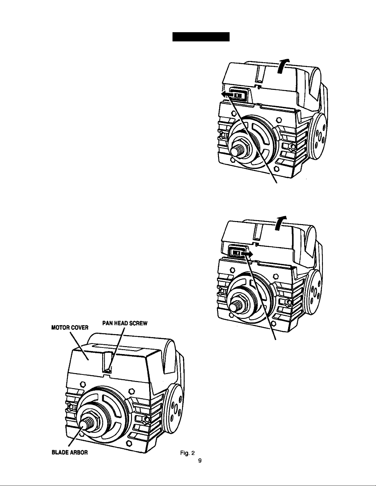
■ Remove the pan head screw above the blade
arbor on the motor cover. Lift motor cover to
expose switch. See Figure 2.
■ Use a small screwdriver to slide the dual voltage
switch to the 240V position. See Figures 3 and 4.
■ Reinstall motor cover.
■ Replace the 120V plug on the main cord with a UL
listed 240V, 15 amp, 3-prong plug.
■ Follow the instructions provided with the UL listed
plug.
■ Plug the cord into a 240V, 15 amp, 3-blade recep
tacle. Make sure the receptacle is connected to a
240V AC power supply through a 240V branch
circuit that has a 15 amp fuse or circuit breaker.
Note: No adapter is available for this type of plug or
receptacle.
LIFT MOTOR COVER TO EXPOSE SWITCH
SLIDE AS SHOWN FOR SINGLE VOLTAGE CIRCUITS
SWITCH SHOWN IN 110-120 VOLT POSITION
Fig.3
UFT MOTOR COVER TO EXPOSE SWITCH
SLIDE AS SHOWN FOR DUALVOLTAGE ClflCUrTS
SWITCH SHOWN IN 220-240 VOLT POSITION
Fig. 4
CflRFTIHflr RADIAL SAW 315.220381

PRODUCT SPECIFICATIONS
Blade Arbor
5/8 in. Cutting Capacity - Maximum In-Rip
16 in.
Blade Diameter 10 in.
Blade Bevel Angle O’ - 90’
Radial Arm Swing Range 45' minimum left - 90* right
Blade Height Adjust 5.35 in.
Carriage Travel 17.25 in.
Cutting Capacity - Maximum Cross Cut 15.50 in.
Cutting Capacity - Maximum Out-Rip 26 in.
Depth of Cut at 90*
Depth of Cut at 45*
Table Size
Table Height
Rating
Input
No Load Speed
3 in.
2.25 in.
40 X 27.75 X 1 in.
36 in.
120V/240V 60 Hz - AC only
13.0/6.5 Amperes
3,600 RPM
GLOSSARY OF TERMS FOR WOODWORKING
Bevel Cut
A cut made across a workpiece with the blade at any
angle other than 90* to the table surface.
Chamfer
A cut removing a wedge from a block so the end (or
part of it) is angled rather than at 90 degrees.
Climb
A hazard in which the blade “climbs" over and out of
the workpiece, pulling the stock out of the operator’s
hands or running across the workpiece.
Compound Cut
A cross cut vwth both a miter angle and a bevel angle.
Cross Cut
A cutting operation with the blade parallel to the
carriage arm and the blade teeth pointing down. It can
be across or with the grain, normally across the grain
or width of the workpiece.
Dado Cut
A non-through cut that leaves a square notch or
trough; requires a special blade.
Featherboard
A device to help guide workpieces during rip cuts.
Fence
A piece of wood used as a edge guide for the
workpiece. Located perpendicular to the carriage arm.
Can be placed at different distances from the rear
table edge in combination witii the other table pieces
and is secured with table clamps.
Freehand
Dangerous practice of making a cut without using a
fence.
Gum
A sticky, sap-based residue from wood products.
Heel
Alignment of the blade to the fence.
Infeed
The side of the blade where the blade teeth point up,
opposite the anti-kickback pawls.
In-Rip
A type of rip cut in which the blade is between the
column and the motor.
Kerf
The space left by the removal of material in a cut or
the slot produced by the blade in a non-through cut.
Kickback .
A hazard that can occur when blade binds or stalls,
throwing workpiece back toward operator.
Leading End
The end of the workpiece pushed into the cutting tool
first.
Miter Cut
A vertical cut made at any angle other than 0* across
the workpiece.
Molding
A shaping cut that gives a varied shape to the
workpiece and requires a special blade.
Out-Rip
A type of rip cut in which the motor is between the
blade and the column. (The blade is “outside” the
motor).
Pushstick
A device used to feed the workpiece through the saw
blade during cutting operations. It helps keep the
operator's hands well away from the blade.
Rabbet
A type of cut that gives a notch in the edge of a
workpiece.
Resaw
A cutting operation to reduce the thickness of the
workpiece to make thinner pieces.
CRRFrSMRir RADIAL SAW 31S.220381
10

GLOSSARY OF TERMS FOR WOODWORKING (Cont.)
Resin
A sticky, sap-based substance.
Rip Cut
In a radial saw, a cut made with the blade parallel to
the fence and perpendicular to the arm. Can be
across or with the grain. The teeth point up at the
point of contact with the wood.
Sawblade Path
The area directly in line with the blade — over, under,
behind, or in front of it. Also, the workpiece area which
will be or has been cut by the blade.
Set
The distance that the tip of the saw blade tooth is off
set from the face of the blade.
Throw-Back
Saw throwing back a workpiece simiiar to kickback.
Through Sawing
Any cutting operation where the blade extends
completely through the workpiece.
Trailing End
The workpiece end last cut by the blade in a rip cut.
Workpiece
The item on which the cutting operation is being done.
The surfaces of a workpiece are commonly referred to
as faces, ends, and edges.
Worktable
The surface on which the workpiece rests while
performing a cutting operation.
UNPACKING
WARNING: To prevent accidental starting that
could cause possible serious personal injury,
assemble all parts to your saw before connecting
it to power supply. The saw should never be
connected to the power supply when you are
assembling parts, making adjustments, installing
or removing blades, or when not in use.
WARNING: If any parts are missing, do not
operate this tool until the missing parts are
replaced. Failure to do so could result in possible
serious personal injury.
■ Carefully remove all parts from the carton and
place the saw on a level work surface. Separate
and check against the list of loose parts.
■ Do not discard the packing materials until you have
carefully inspected the saw, identified all parts, and
satisfactorily operated your new saw.
Note: If any parts are damaged or missing, do not
attempt to plug in the power cord and turn the
switch on until the damaged or missing parts
are obtained and are installed correctly.
ACCESSORIES
The following recommended accessories are currently available at Sears Retail Stores.
■ Steel and carbide tipped circular saw blades ■ Adjustable taper jig
■ Hold down clamps ■ Sawdust collector shroud
■ Saw baskets
^ WARNING: The use of attachments or accessories not listed might be hazardous.
11
CRHFnNRr RADIAL SAW 315,220381
LOOSE PARTS LIST
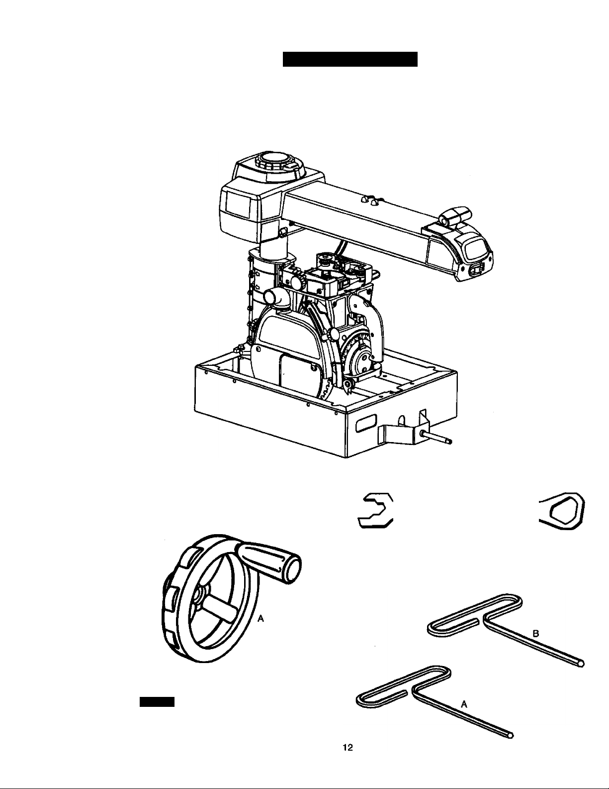
1. Saw Assembly...............................................................1
Check all loose parts from the box with the list below. Use the instructions on the following pages to assemble.
All fasteners are shown actual size.
SAW ASSEMBLY SHOWN AS PACKED
2. Elevating Handwheel
A. Hendwheel
......................
.
..............
.
......................
i
B. Screw (10-24 x 5/8 in, Soc. Hd.)
...........................
1
C. Star Washer
...............................
.
..........................
1
3. Blade Wrench.
Fig. 5
.....
2
4. Hex Key
A. 3/16 in. Hex Key.
B. 1/4 in. Hex Key...
B
o
URFIXMlIir RADIAL SAW 315.220381
Fig. 6A
LOOSE PARTS LIST
Check all loose parts from the box with the list below. Use the instructions on the following pages to assemble.
All fasteners are shown actual size.
5. Saw Base To Leg Stand Assembly
A. Saw Assembly (not shown)
.................................
1
B. Leg Stand Assembly (not shown)
.......................
1
C. Hex bolt (5/16-18 x 5/8 in. Hex Head)
..................
4
D. Washer (5/16 in.)
...................................................
8
E. Lock washer (5/16 in.)
..........................................
4
F. Hex Nut (5/16-18)....................................................4
^ (o) @
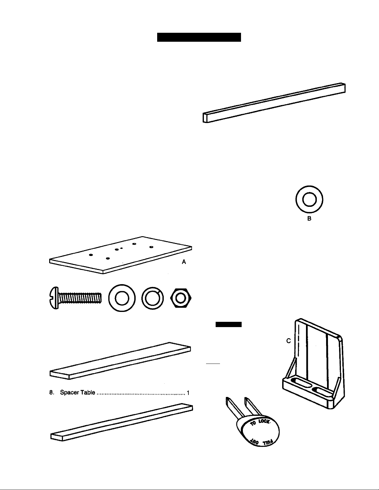
6. Hardware for Front Table
A. Front table.......................................................... 1
B. Screw (1/4-20 x 1 in.)
.......................................
4
C. Washer (1/4 in.).....................................................4
D. Lock washer (1/4 in.)
.......................................
4
E. Hex nut (1/4-20)
....................................................
4
B
7. Rear Table.
9. Fence.
1
10. Leveling Hardware for Front Table
A. Screw (1/4-20 x 1-3/4 in.).....................................1
B. Washer..................................................................1
C. U-clip
....................................................................
1
D. Setscrew.
E. Tee nut....
I
dD
N
11. Scale Indicator
A. Screw.....................................................................4
B. Speed Nut..............................................................2
C. Indicator................................................................2
D. Switch Key............................................................2
0
mmuiumv
inrour
13
Fig. 6B
CRAFTIMRir RADIAL SAW 315.220381
LOOSE PARTS LIST
Check all loose parts from the box with the list below. Use the instructions on the following pages to assemble.
All fasteners are shown actual size.
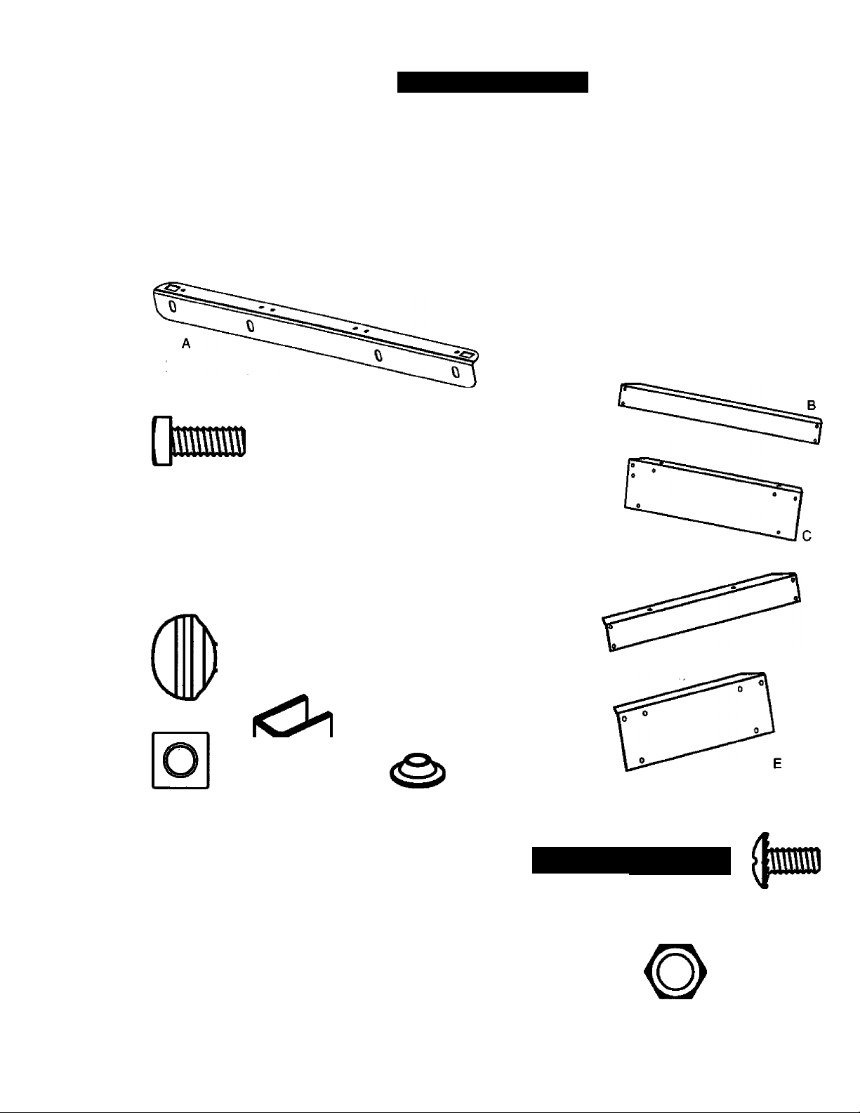
12. Table Support
A. Table Support Ralls..............................................2
B. Square,head bolt (5/16-18 x 3/4 in.)
....................
4
C. Flat washer (5/16 in.)............................................4
D. Lock washer (5/16 in.)..........................................4
E. Hex nut (5/16-18).................................................. 4
(o)
B
13. Table Clamp
......................
.......................................
2
A. Thumb screw (2)...................................................2
B. Square nut.............................................................2
C. Table clamp bracket
.............................................
2
D. Cup washer
...........................................................
2
B
14. Owner's Manual (not shown)
15. Leg Stand....................................................................i
A. Leg........................................................................4
B. Long bottom brace
..............................................
2
C. Long top brace
....................................................
2
D. Short bottom brace
.............................................
2
E. Short top brace....................................................2
F. Foot.......................................................................4
G. Screw (1/4-20 X 5/8 in.).......................................40
H. Star washer
........................................................
40
I. Hex nut (1/4-20)
...................................................
40
J. Hex nut (3/8-16).....................................................8
0 O
Huunwuuuuwuwwu
U-
o ©
H
Fig. 6C
CRRfTSMHir RADIAL SAW 315.220381
14
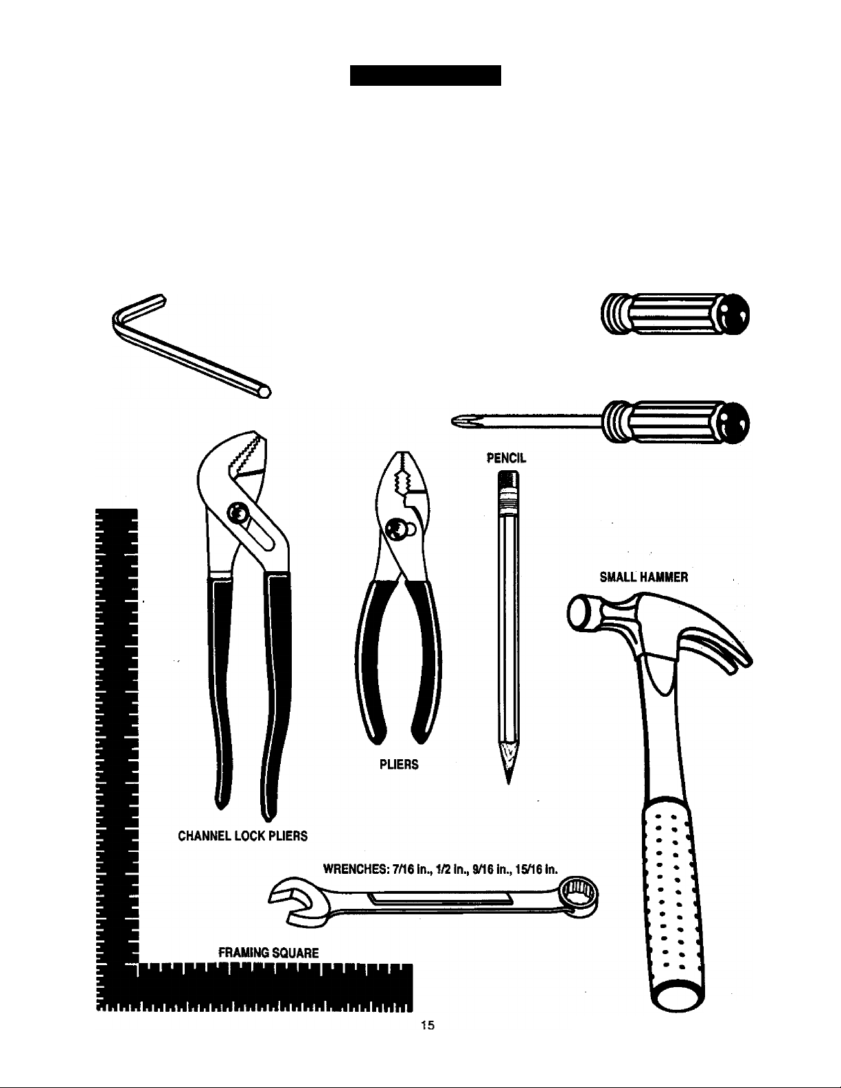
TOOLS NEEDED
The following tools are needed for assembly and alignment. They are not included with this saw.
HC
)HC
3
HEX KEYS:
&32 in. AND 1/8 in.
LEVEL
MEDIUM FLAT BLADE SCREWDRIVER
#2 PHILLIPS SCREWDRIVER
Fig. 7
[RHFTSMRir RADIAL SAW 315.220381
в
^ 10 inch Radial Arm Saw ^
3.600 ЯРМ 120/240 VOLTS 13/6.5 Amp 60 lb AC ONLY
WHEN SERWCING. USE ONLY IDENTICAL CfWTSMAN
repucementpArts.
MOKL315JSM)381
шоеншппм
SEARS, HOtBUCKAWP CO.
ser.no.
[
n
\ Üjstomer Help Une 1S00‘^3M188 J
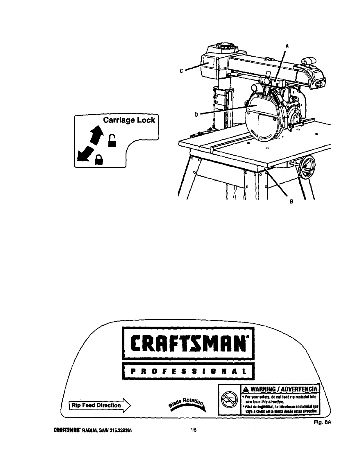
A WARNING / ADVERTENCIA
• For your own safety. Read and understand
ovmer's manual before pi^rating saw.
• This tool has more than one connection to the
power source.
»To reduce the risk of electrical shock or injury,
disconnect all power connections
• When servicing, use only identical
replacement parts.
• Para su seguridad, lea у entienda el manual del
propietario antes de operar la sierra.
Control Cut
Speed Adjustment
+
A WARNING
ADVERTENCIA
For your lafety, read ownen maoual before opetaUng
taw.
Wear safety gaggles.
Do not perform fneband cols.
• flelarn carriage to full rear position alter each cross cut.
See insiructlons on how to reduce the risk of ktcItbaiA.
When ripping, use pushstick «then blade is set Z Indies or mote from
fenca.
When ripping, use pushblock and auxiliary fence when hlade it tel between
1/Z and 2 iiKhet from fence. Do not make rip cuts nairower than 1/2 inch.
• Keep hands out of path of blade.
Do not reach aroond taw blade.
Itim power on and wait for blade to stop before moving workpiece or
changing settings.
Unplug saw before changing the blade or servicing.
Para su segurldad, lea y entienda el manual del prcpietarlo antes deopararia sierra
A WARNING
ADVERTENCIA
• Read and understand owners manual
before operating saw.
• For your safety, do not use
accessories without proper guarding.
• Provide proper workpiece support
• Position cutting tool behind the
fence.
• With power off and switch key
removed, turn cutting tool by hand to
make sure it does not strike guard,
fence or any other saw parts.
• Para su seguridad, lea y entienda el
manual del propietario antes de
operar la sierra.
LOCKED
V
i
UNLOCKED
■ PIVOT 1b
17
Fig. 8B
CRHFTSMRir RADIAL SAW 315.220381
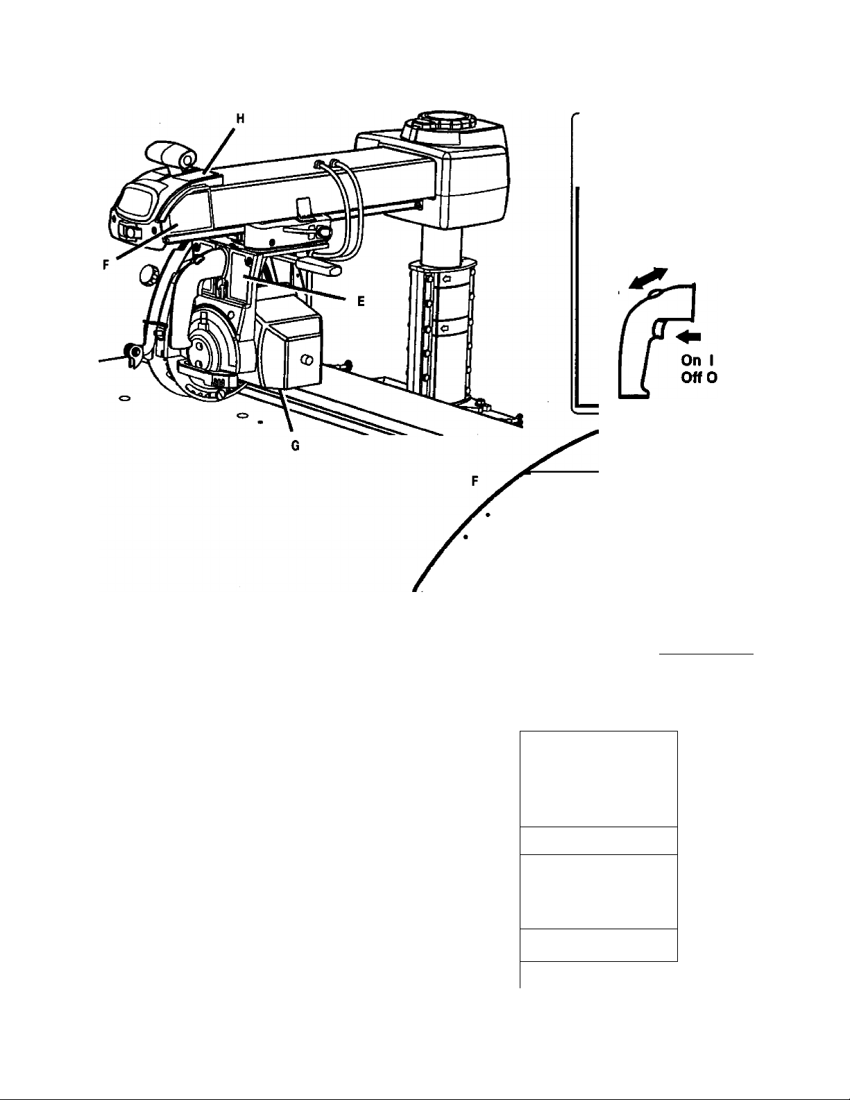
FEATURES
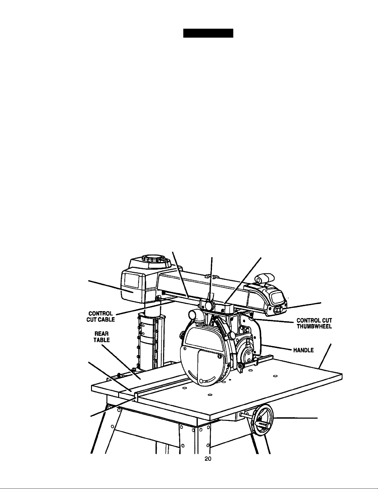
KNOW YOUR RADIAL SAW
See Figure 9A.
OVERVIEW - The main operating components include
the column, the arm, and the yoke assembly (yoke,
motor, and blade), and their operation is summarized
in the paragraph below. Safety features and control
functions are given also. Spending a few minutes
reviewing the iiiustrations and features list below and
on the following pages to locate these items will make
assembly easier.
METHOD OF OPERATION: The column at the back
of the saw supports the radial arm. The arm can be
raised or lowered to change the blade height or
swiveled left and right for a miter cut. A yoke fits into
a carriage on the arm, which can travel back and
fonward. The yoke supports the yoke assembly
(motor, blade, and blade guard) and can be pivoted
so the blade faces right, front, or left. The motor can
be rotated to change the blade angle.
YOKE
ARM LOCK KNOB
SWITCH AND KEY
BLADE AND
BLADE GUARD
Control functions include 1) column height {elevating
handwheel), 2) arm angle (arm lock knob). 3) yoke
movement on arm (‘carriage lock knob) 4) yoke
rotation (‘yoke pivot latch and ‘yoke lock handle), and
5) blade bevel (‘bevel index lever and ‘bevel lock
knob).
Safety features include the control cut device, the
removable switch key, and the blade guard assembly.
Never operate the saw without ensuring these safety
features are in place and functioning correctly.
On a radial saw, “cross cuf means a cut parallel to
the arm, and a "rip cuf is perpendicular to the arm.
There are several ways to make cuts, depending on
the size and material of the workpiece and the end
result desired.
Before attempting to use your saw, familiarize yourself
with all operating features and safety requirements of
your Sears Craftsman Radial Arm Saw.
‘Shown on following pages
CONTROL
CUT HOUSING
ARM
COLUMN
ELEVARNG
HANDWHEEL
CRUFTSMUir RADIAL SAW 315.220381
Fig. 0A
FEATURES
FEATURES LIST
See Figures 9A-9D.
ADJUSTABLE TABLES - A narrow spacer table and
wider rear table that can be repositioned or even
replaced with different tables. See Figure 9C.
ANTI-KICKBACK PAWLS - Toothed pawls that snag
the work in case of kickback during rip cuts. (When
the blade is parallel to the arm, the pawls are in front
of the blade.) Keep the pawls in place to reduce risk
of injury. See Figure 9D.
ARM - The assembly extending from the column,
which supports the yoke, the motor, and the blade.
See Figure 9A.
ARM LOCK KNOB - Controls arm angle. Use to set
the arm to the positive stops at O', 45' left, and 45*
right and to lock the arm in place. Located on top of
arm at front. See Figures 9A and 9B.
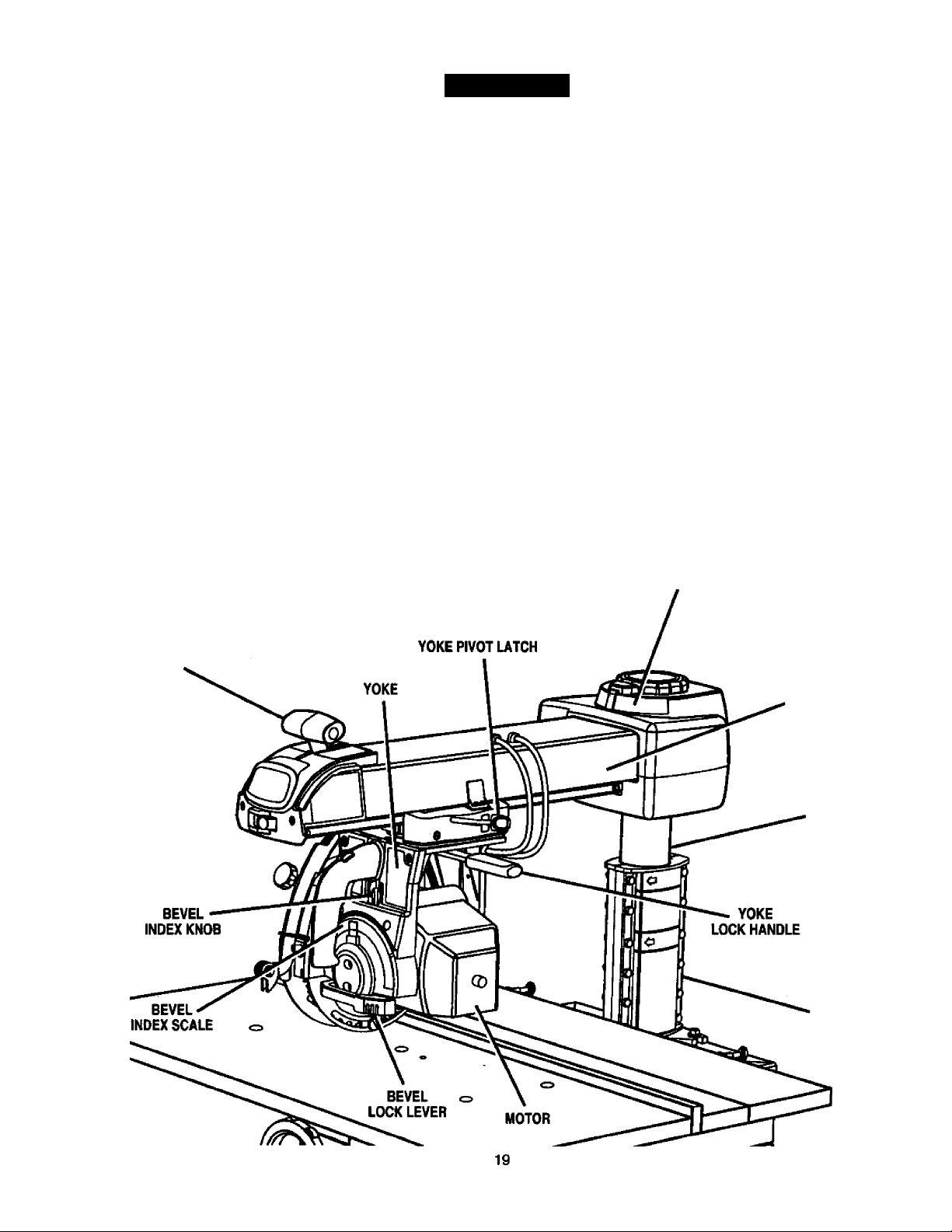
BEVEL INDEX KNOB - Controls the blade angle
between positive stops at O', 45', and 90*. Located
behind the handle. See Figure 9B.
BEVEL INDEX SCALE - Shows the blade angle for
bevel cuts and is located behind the handle. See
Figure 9B.
BEVEL LOCK LEVER - Sets and locks blade angle. It
is located below the handle. See Figure 9B.
BLADE - For maximum performance, use the Crafts
man 40-tooth, 10 in. carbide-tipped blade provided
with your saw. It is a high-quality combination blade
suitable for ripping and crosscut operations. Blades
recommended for other operations are listed in the
Accessory section of this manual. The blade is
powered by the main motor and turned off by the
switch. See Figure 9D.
WARNING: Use only blades rated for at least
5,000 rpm and recommended for use on this
saw. Check with your nearest Sears retail store.
BLADE GUARD ASSEMBLY - Protective unit over
the blade, with a riving knife, anti-kickback pawls, an
upper blade guard, a lower outer blade guard, and a
lower inner blade guard. Always keep each item in
place unless specifically instructed to move it. See
Figures 9A and 9D.
BLADE GUARD CLAMP SCREW - Secures the
blade guard to the motor. Located between the blade
and the motor. See Figure 9D.
MITER SCALE
ARM LOCK KNOB
RIP
SCALE(S)
COLUMN TUBE
COLUMN SUPPORT
Fig. 9B
CUFTSMflir RADIAL SAW 315.220381
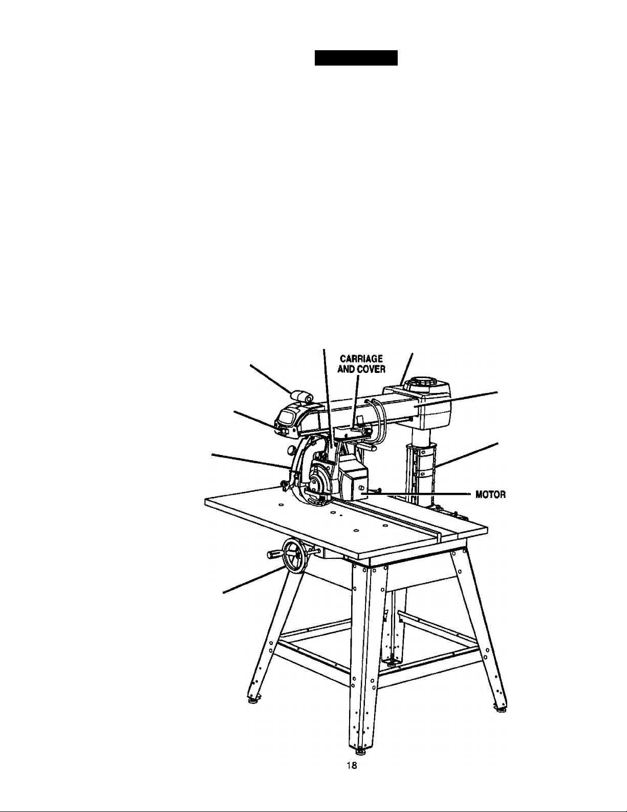
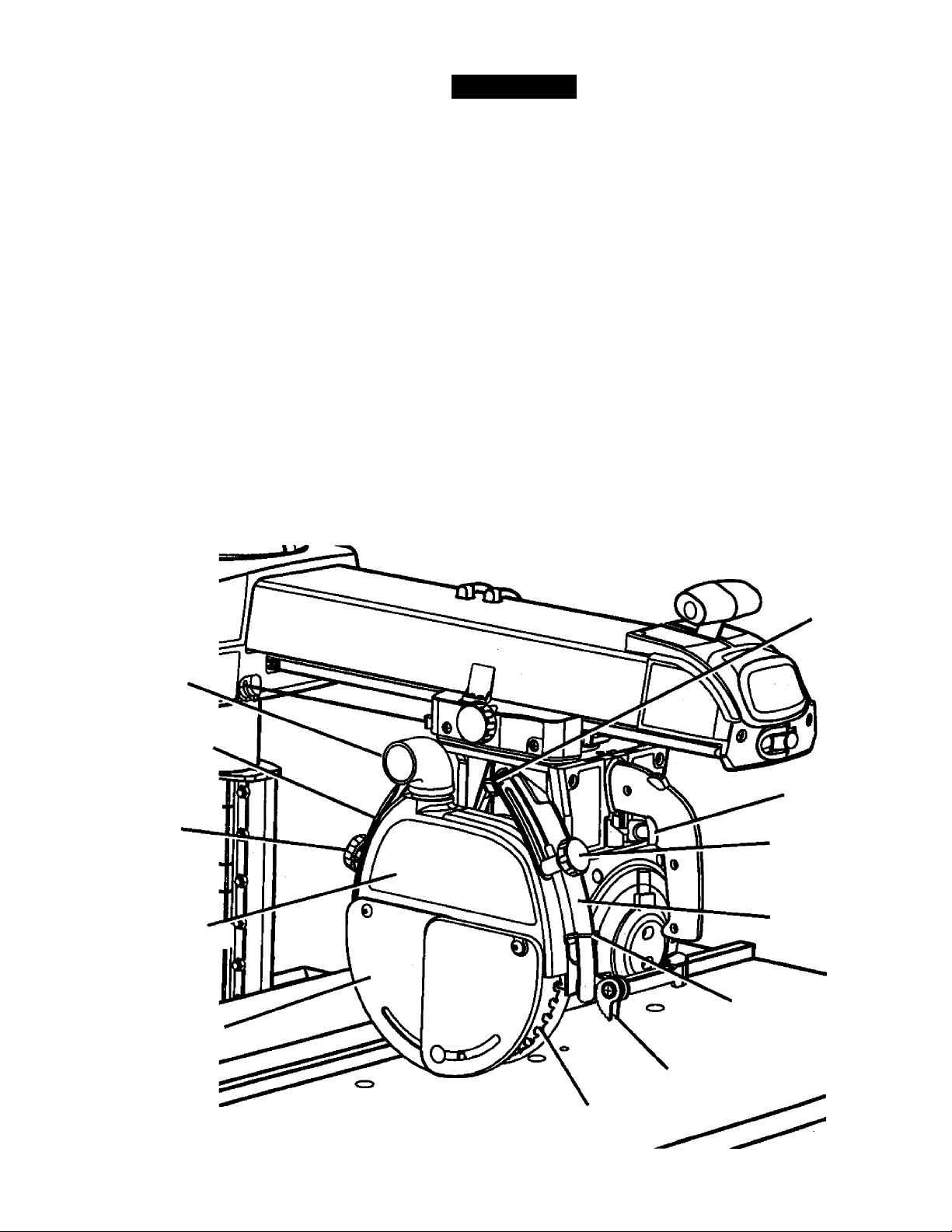
FEATURES
CARRIAGE - Slides along track under arm and
supports yoke. Contained in two carriage covers, one
on each side of the arm. See Figure 9C.
CARRIAGE LOCK KNOB - Controls whether the
carriage is locked or can travel. Located on the left
side of the arm on the carriage cover. See Figure 9C.
COLUMN - Upright housing at the back of the saw,
consisting of a column support and a column tube.
The column tube can be raised or lowered with the
elevating handwheel at the front of the saw. See
Figures 9A and 9B.
CONTROL CUT DEVICE - Limits carriage speed to
prevent climb, using a cable from the carriage to the
column. Has a separate motor on left side, which is
activated by the switch trigger in the handle. The
cable returns the carriage to the column when the
motor is not activated. Speed is adjusted with a
thumbwheel on the handle. It runs on a separate
120V AC single voltage circuit. See Figure 9C.
A WARNING: When connecting only one of the
cords, squeeze the switch trigger in the handle. If
the main motor cord alone is connected, the
switch trigger in the handle will not operate the
control cut device. The carriage cannot be
advanced without power to the control cut device.
DUAL VOLTAGE - If needed, your main power
source may be rewired by a qualified electrician to
provide a 240V AC circuit. See the E/ecfr/ca/section.
DUST GUIDE - Directs sawdust, created from the cut
being made, in the direction you set. Located at the
rear of the upper blade guard. See Figure 9D.
ELEVATING HANDWHEEL - The handwheel below
the worktable (in front) that changes the height of the
arm and the blade. See Figure 9C.
FENCE - Removable guide for work, which extends
across width of table. See Figure 9C.
FRONT TABLE - Fixed portion of the worktable that
supports the work. See Figure 9C.
HANDLE - Used to pull the yoke assembly. Mounted
on the yoke to the right of the blade. See Figure 9C.
HOLD DOWN - A metal guard to control workpiece
climb during rip cuts. When blade parallels arm, hold
down is over the back of the blade. See Figure 9D.
HOLD DOWN KNOB - Controls placement of the hold
down and locks it in place. See Hgure 9D.
MITER SCALE - Shows the miter angle setting of the
arm. See Figure 9B.
TRACK CARRIAGE
LOCK KNOB
CARRIAGE
AND COVER
CONTROL
CUT MOTOR
SPACER
TABLE
FENCE
SWITCH
AND KEY
FRONTTABLE
ELEVATING
HANDWHEEL
Fig. 9C
CRRFTSMRN* RADIAL SAW 315.220381
FEATURES
MOTOR (13/6.5 AMP) - Powers the blade and is
controlled by the switch and key at the front of the
arm. The powerful induction motor has a capacitor
start. It is mounted in the yoke and rotated with the
bevel index knob and bevel lock lever. See Figure 9B.
RIP SCALES - Show the distance from the fence to
the blade. (In-rip scales are on the right side of the
arm, and out-rip scales are on the left side.) Upper
scales show the distance with the fence beside the
front table. Lower scales show the distance with the
fence in farthest back position. See Figure 9B.
RIVING KNIFE OR SPREADER - Located directly in
front of the blade and beside the anti-kickback pawls,
the riving knife keeps cut edges from binding during
rip cuts. See Figure 9D.
RIVING KNIFE BRACKET - Allows adjustment of the
riving knife. Located midway along the riving knife.
See Figure 9D.
RIVING KNIFE KNOB - Adjusts the riving knife and
locks both the pawls and the riving knife in place.
Located toward the top and front of the blade guard.
See Figure 9D.
SWITCH TRIGGER - Used to power the control cut
device to allow yoke assembly to be pulled forward.
Mounted in the handle. See Figure 9D.
SWITCH WITH KEY - Powers the blade motor.
Placed on the front of the arm for easy access. To
lock the switch once it has been pressed to OFF,
remove the yellow key. Place the key in a location that
is inaccessible to children and others not qualified to
use the tool. See Figures 9A and 9C.
YOKE - Supports the blade and motor. Can be
pivoted to index the blade between rip and cross cuts.
Located between the carriage and the motor. See
Figure 9B.
YOKE PIVOT LATCH - Indexes the yoke (after it is
released) to position the blade to face right (out-rip
cut), front (cross cut), or left (in-rip cut). Located on
the right carriage cover. See Figure 9B.
YOKE LOCK HANDLE - Releases the yoke to allow
indexing for rip cut or cross cut. Located below the
yoke, on the right. See Figure 9B.
BLADE GUARD
CLAMP SCREW
DUST GUIDE
HOLD DOWN
HOLD
DOWN KNOB
SWITCH
TRIGGER
UPPER
GLADE GUARD
LOWER
BLADE GUARD
RIVING
KNIFE KNOB
RIVING KNIFE
RIVING
KNIFE BRACKET
ANTI-KICKBACK
PAWLS
BUDE
21
Fig. 9D
CRRFTXMRr RADIAL SAW 315.220381
ASSEMBLY
Assembly is best done in the area where the saw will
be used. When you remove the saw and hardware
from the packing materials, carefully check the items
with the Loose Parts list. If you are unsure about the
description of any part, refer to their illustrations. For
your convenience, all fasteners have been drawn
actual size. If any parts are missing, delay assembling
until you have obtained the missing part(s).
Your radial arm saw is capable of a wide variety of
operations, and thus requires a number of initial setup
adjustments. However, once the saw is set up, you
can check your saw in about ten minutes and correct
any misalignment with the procedures in the Adjust
ment section.
A CAUTION: Perform all the procedures In both
the Assembly and Adjustments sections before
using the saw. Run a check on your saw
frequently, referring to the Adjustments section.
Failure to perform the adjustments in the initial
set up or on a frequent basis can result in poor
performance or machine damage.
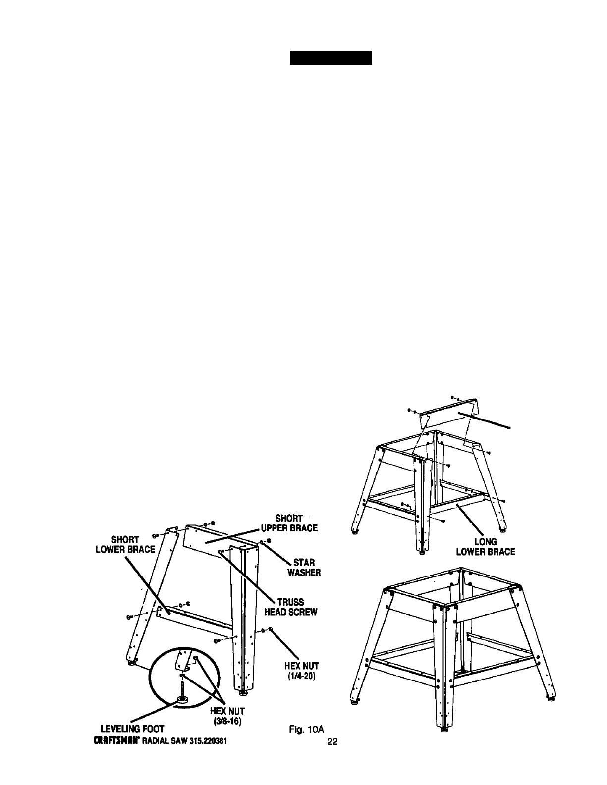
ASSEMBLING LEG STAND
See Figures 10A - IOC.
■ Take the following hardware from the hardware
bags in tile leg stand carton:
40 truss head screws (1/4-20 x 5/8 in.)
40 star washers (1/4 in.)
40 hex nuts (1/4-20)
■ Take the following hardware from the remaining
hardware bags in the leg stand carton:
4 leveling feet
8 targe hex nuts (3/8-16)
■ Obtain four legs and eight braces from the leg
stand carton. See the Loose Parts section.
Place a 3/8-16 hex nut on each leveling foot and
Insert leveling feet into the bottom of the legs. Cap
with remaining 3/8-16 hex nuts but only finger
tighten. See Figure 10A.
Place a short upper brace inside two of the legs
(wide end of legs up) and align the three holes in
the brace with the holes in the legs.
Insert the screws. Add the star washers and 1/4-20
hex nuts. Finger tighten.
Instail a short lower brace on the legs.
See Figure 10A.
Repeat for the other end assembly.
Connect the leg sets with a long upper brace. Add
the hardware and finger tighten. Repeat for the
other side brace, then install the long lower braces.
See Figure 10B.
Tighten all screws, washers, and nuts with a 7/16
in. wrench and as needed a #2 phillips screwdriver.
Move the leg stand to the desired location. Using a
level, adjust the leveling feet by raising or lowering
tile bolts with a 9/16 in. wrench.
When the leg stand is level, securely tighten all four
nuts with the wrench.
Your leg stand is now completely assembled and
ready for use. See Figure IOC.
LONG
UPPER BRACE
Fig. 10B
Fig. IOC
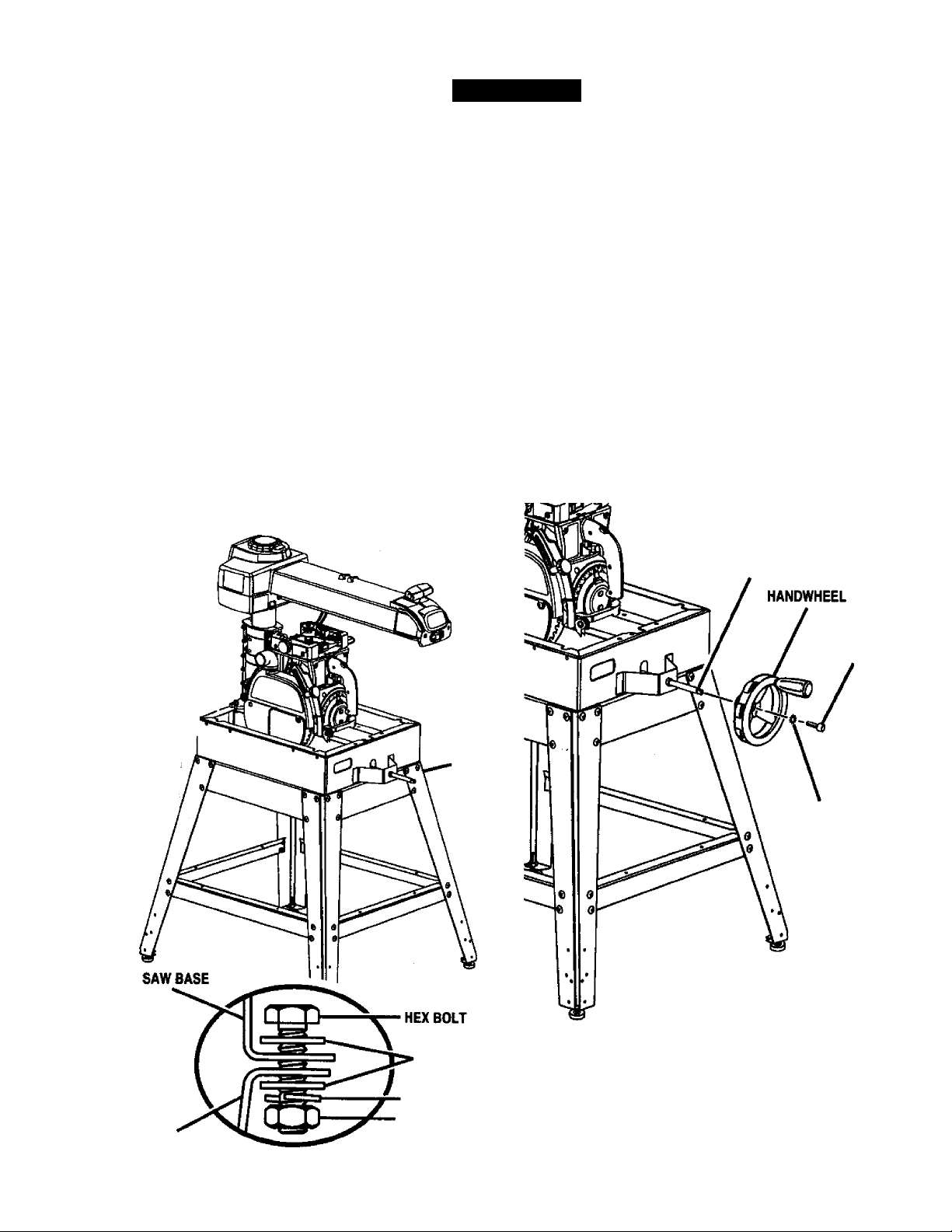
ASSEMBLY
WARNING: Firmly bolt the saw to the leg stand
to keep the saw from tipping, walking, or sliding.
■ Locate the following hardware from a small hard
ware bag;
4 hex bolts (5/16-18 X 5/8 in.)
4 lockwashers (5/16 in.)
8 flat washers (11/32 in.)
4 hex nuts (5/16-18)
■ Place the saw on top of the leg stand so the holes
in the saw base line up with the holes on top of the
leg stand braces.
■ Put a washer on a screw, and put the screw and
washer into the hole in the saw base. Cap with
another washer, then a lockwasher and a hex nut.
Hand tighten the set.
■ Install the other three sets and securely tighten all
four sets with a 1/2 in. wrench.
MOUNTING SAW TO LEG STAND
See Figure 11.
SAW^
BASE
LEG
STAND
LEG STAND
FLAT
WASHER
LOCKWASHER
HEX NUT
Fig. 11
ATTACHING ELEVATING HANDWHEEL
See Figure 12.
A WARNING: Be sure the main power cord of
your saw is unplugged. Ignoring this precaution
could result in serious injury. Do not perform the
following steps unless the saw is unplugged.
The elevating handwheel adjusts the height of the
radial arm and the blade.
■ Take the handwheel, star washer, and screw
(10-24 X 5/8 in. Soc. Hd.) from the hardware bag.
■ Place the handwheel on the end of the elevating
shaft, which extends from the front of the saw base.
■ Place the star washer on the screw and thread
screw into the end of the shaft.
■ Securely tighten the screw with a 5/32 in. hex key.
■ Raise or lower the arm by turning the handwheel.
ELEVATING
SHAR
SCREW
STAR WASHER
Fig. 12
23
CRflFTSMRN* RADIAL SAW 315.220381
ASSEMBLY
The yoke rides in the carriage below the arm and
supports the motor, the blade guard, and the blade.
Install the yoke assembly from the front of the arm.
■ Remove the carriage stop screw and lockwasher
from below the front of the arm with a 1/4 in. hex
key. See Figure 13A.
ARM VIEWED FROM BELOW
INSTALLING THE YOKE ASSEMBLY
See Figures 13A - 13C.
FOR CLARITY, CARRIAGE COVERS AND CARRIAGE LOCK
KNOB ARE NOT SHOWN IN ILLUSTRA'RON
ARM LOCK KNOB
BEARINGS (4)
CARRIAGE
n
---------
-
------
LOCKWASHER
CARRIAGE STOP SCREW
1/4 in. HEX KEY Fig.13A
Remove the arm cap screws and arm cap from the
front of the arm with a philltps screwdriver. See
Figure 13B.
YOKE
CARRIAGE
LOCK KNOB
ARM
ARM LOCK KNOB
Fig, 13B
Remove and discard the two motor setscrews in
the bottom of the motor. They are for shipping
purposes only.
Using the elevating handwheel, raise the arm 3
inches and remove the packing material.
Lock the arm with the arm lock knob, located on top
of the front of the arm, so the arm doesn’t swing
while you are mounting the yoke assembly.
Pick up the yoke assembly and carefully slip it onto
the carriage track below the arm. Keep it parallel
with the arm so bearings slide In smoothly. See
Figure 13C.
CARRIAGE COVER
13C
Reinstall the carriage stop screw, the lockwasher,
arm cap, and arm cap screws. Tighten all screws
securely.
^ WARNING: Once the yoke assembly is on the
* carriage track, reinstall the arm cap, №e arm cap
screws, the carriage stop screw, and the
lockwasher. Do not risk serious injury or damage
to the saw by falling to replace these parts.
Tighten the carriage lock knob, on the carriage
cover on the left of the arm, to lock the yoke
assembly in place.
CRRFTSMRir RADIAL SAW 315.220381
24
ASSEMBLY
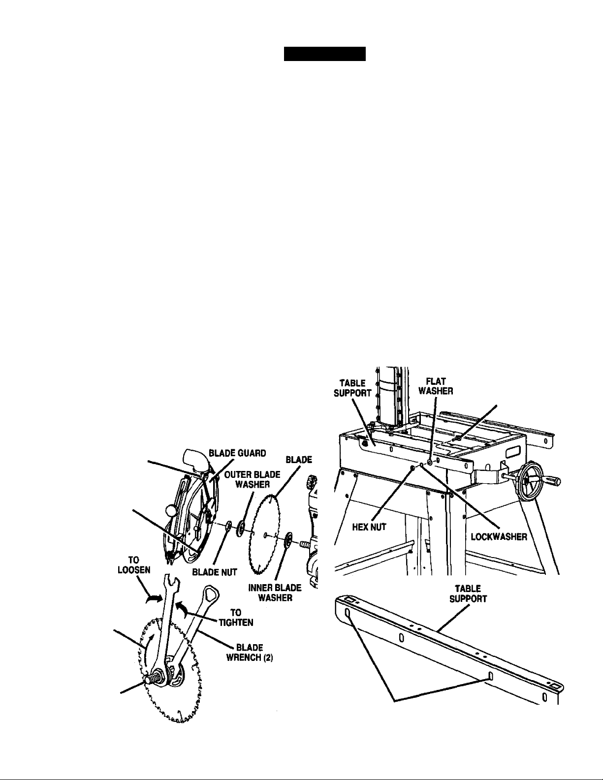
REMOVING THE BLADE
See Figure 14.
Remove the blade and blade guard assembly during
setup for safety and better access. The blade guard
includes an upper blade guard, an outer lower guard,
and an inner iower guard. The lower inner guard
consists of two overlapping slotted metal strips. The
strips are held together with a retaining screw and a
nut. Locate these items before beginning the proce
dure.
WARNING: To prevent accidental contact with
the blade that could result in injury, remove the
blade and blade guard before making setups
involving the blade arbor and work stand. Use
the blade wrenches provided with your saw.
■ Remove the retaining screw and nut at the bottom
of the lower inner blade guard.
■ Loosen the guard clamp screw, a long thumbscrew
between the blade guard and the motor.
■ Rotate and lift the guard assembly up and over the
blade, then remove it,
■ Hold the blade arbor (motor shaft) with one of the
two blade wrenches provided. Put the other blade
wrench on the blade nut and turn it clockwise
(down), since the blade arbor has left hand threads.
■ Remove the blade nut, outer blade washer, saw
blade, and inner blade washer. Set these items
aside until ail the tables have been installed and the
front table is level.
THUMBSCREW
The table supports are a base for the three wooden
table sections and fence.
■ Locate the two table supports and the following
hardware:
4 square head bolts (5/16*18 x 3/4 in.)
4 lockwashers (5/16 in.)
4 hex nuts (5/16-18)
4 flat washers (5/16 in.)
■ Attach the supports to the side of the saw base.
There are holes in both sides of each support. The
long side of each support (with the slotted holes)
fits against the saw base.
■ Use two square head bolts per support, inserted
from within the saw base outward.
■ Place a flat washer, a lock washer, and a hex nut
on the end of each screw.
■ Position table supports so that bolts are approxi
mately centered in slotted holes.
B Finger tighten or snug with a 1/2 in. wrench only at
this time. Final adjustments will be made later in
Leveling The Table Supports section.
ATTACHING TABLE SUPPORTS
See Figure 15.
SQUARE
HEAD BOLT
RETAINING
SCREW AND NUT
BUDE
ARBOR
BUDE
ROTATION
MOUNT TABLE SUPPORTS
Fig. 14 USING THESE HOLE LOCATIONS Fig. 15
25 CRAFTSMAN* RADIAL SAW 3t5.2203«1
 Loading...