


WZT1500 I.S. 325-1394 10/28/03 3:41 PM Page 1
Instruction Manual
Manual de Instrucciones
Directives
WZT1500
1500 Watt Stand Light
FRANÇAIS ESPAÑOL ENGLISH
1
WZT1500 I.S. 325-1394 10/28/03 3:41 PM Page 2
ENGLISH
WZT1500
1500 Watt Stand Light
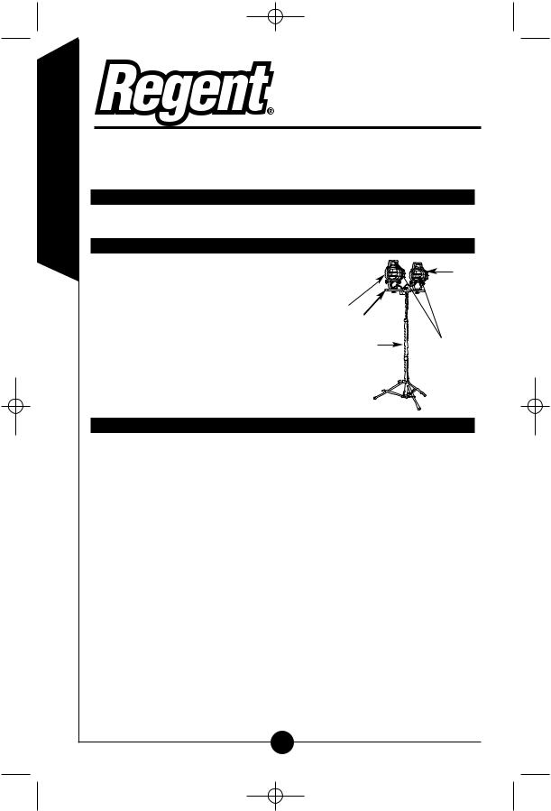
Congratulations! You have purchased a Regent 1500-watt stand light. This versatile light is perfect for many different applications where a wide area of light is needed.
What you need:
• Pliers/wrench
What’s included:
• (2) Light fixtures (A) |
|
E |
|
• Crossbar (B) |
|
|
|
• Adjustable pole and stand (C) |
A B |
|
|
• (3) 500 Watt halogen bulbs |
|
||
(One located in each fixture, plus |
|
D |
|
BONUS bulb stored in handle) (D) |
C |
||
|
•(2) Protective Grilles (E)
•Hardware Bag
What to know:
WARNING: Risk of fire / electric shock / personal injury. Basic safety precautions should always be followed when using "outdoor use worklights", including the following:
IMPORTANT SAFETY INSTRUCTIONS
READ ALL INSTRUCTIONS
•Use only three wire outdoor extension cords that have three-prong grounding plugs and grounding receptacles that accept the appliance’s plug.
•Ground Fault Circuit Interrupter (GFCI) protection should be provided on the circuit(s) or outlet(s) to be used for the wet location portable lamps. Receptacles are available having built-in GFCI protection and are able to be used for this measure of safety.
•Use only with a minimum 16 AWG extension cord listed for outdoor use, such as an extension cord type SW, SW-A, SOW, SOW-A, STW, STW-A, STOW, STOW-A, SJW, SJW-A, SJOW, SJOW-A, SJTW-A, SJTOW, OR SJTOW-A.
Lighted lamp is HOT!
2
WZT1500 I.S. 325-1394 10/28/03 3:41 PM Page 3
To reduce the risk of FIRE, ELECTRIC SHOCK, EXPOSURE TO EXCES- |
|
|
SIVE UV RADIATION, OR INJURY TO PERSON, please follow the fol- |
|
|
lowing instructions. |
ENGLISH |
|
• WARNING: Risk of burn. Disconnect power and allow fixture to cool |
||
|
||
before changing bulb or handling fixture. |
|
|
• Bulb gets HOT quickly! Only contact switch/plug when turning on. |
|
|
• Do not touch hot lens, guard, or enclosure. |
|
|
• Do not remain in light if skin feels warm. |
|
|
• Do not look directly at lighted bulb |
|
|
• WARNING: Risk of fire. Keep away from flammable vapors and |
|
|
materials |
|
|
• Use only a recommended, or lower wattage halogen type "T" bulb. Use of |
|
|
any other bulb will damage the fixture and void the warranty. Installing |
|
|
higher wattage bulbs could create a fire hazard. |
|
|
• Do not touch the bulb at any time. Use a soft cloth or gloves. Oil from |
|
|
skin may damage bulb. |
|
|
• WARNING: Risk of Personal Injury. Exposure to Ultraviolet (UV) |
|
|
Radiation. Do not operate with a damaged or missing protective barrier. |
|
|
• Do not direct light at persons |
|
|
• Fixture must be connected to a 120 Volt, 60 Hz power source. Any other |
|
|
connection voids that warranty. |
|
|
• The electrical system, and the method of electrically connecting the fixture |
|
|
to it, must be in accordance with the National Electric Code and local |
|
|
building codes. |
|
|
• WARNING: Risk of Electric Shock. Do not use with extension cord near |
|
|
water or where water may accumulate. Keep lamp at least 16 feet from |
|
|
pools and spas. Keep plugs and receptacles dry. For use only on GFCI |
|
|
protected circuits. |
|
|
• Disassembly of the fixture will void the warranty. |
|
|
• If lens is replaced, use only tempered safety glass of equal thickness. |
|
|
• For maximum bulb life, position light so that the halogen bulb remains |
|
|
within 4° of horizontal. |
|
|
• For indoor and outdoor use. |
|
|
• UL / cUL LISTED for wet locations |
|
|
• WARNING: Deviation from these instructions may result in a risk of fire, |
|
|
burns or electric shock. |
|
|
SAVE THESE INSTRUCTIONS |
|
|
|
|
|
Assembling your fixture: |
|
|
Step 1: Remove fixtures, pole, and leg assembly from box. Slide pole into |
|
|
top bracket of leg assembly until it rests in the bottom bracket. |
|
|
Tighten locking bolt in lower bracket with wrench to secure pole. |
|
|
Step 2: Pull legs out, extending to full open position so that the top black |
|
|
bracket slides down until it lines up with red line on label then |
|
|
tighten knob to lock in place (Figure A). |
|
3
WZT1500 I.S. 325-1394 10/28/03 3:41 PM Page 4
ENGLISH
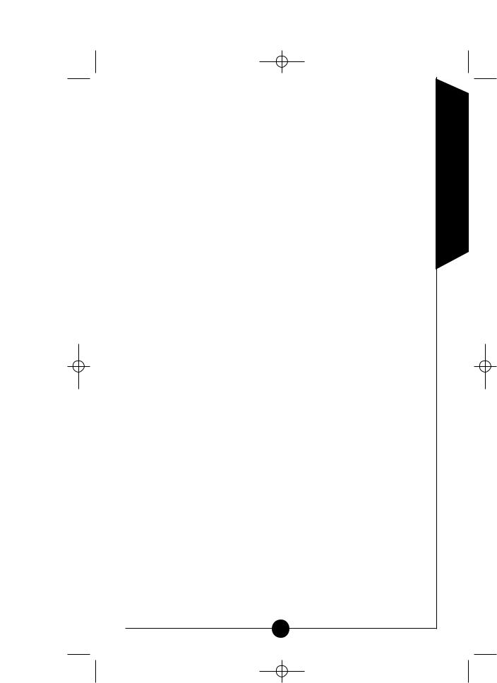
Step 3: To mount each light fixture to the light bar. First, lay fixtures face down on a smooth flat surface. Make sure that the junction box connecting the fixtures and cords are positioned as shown in figure B. Place bolt through the square holes in the crossbar, and then place the bolt through the bracket on the fixture. Place washer onto the bolt and tighten the plastic knob until secure.
Repeat for opposite fixture.
Step 4: To install the wire safety guard, insert one side of the guard between the frame and lens. Squeeze the guard until the other side can be placed between the opposite side of the frame and lens.
Slide bracket down to line up with RED  mark on label
LABEL
Fig. A
Step 5: To attach the light assembly bar to the adjustable pole, position the hole in the middle of the light assembly bar over the threaded screw on the pole. Note: The large hole in the light assembly bar should
facing down to fit over the nut already in place. Once the light assembly bar is in place, position the hole in the junction box over the threaded screw. Secure with attachment knob.
How to Use:
Step 1: Loosen the knob at the top of the leg assembly and pull legs out, extending to full open position
so that the top black bracket slides down until it meets the bottom bracket. Set the stand on a flat surface and release the center pole. Loosen the knob at the top of the leg assembly and pull
legs out, extending to full open position so that
the top black bracket slides down until it lines up with red line on label (Figure A).
Step 2: Plug light into a GFCI protected 120-volt receptacle.
Step 3: Adjust the tripod stand to the desired height by loosening and tightening the locking collars on the pole.
Step 4: To turn light ON, or OFF, push red switches on the back of each fixture. Each fixture has two switches for the following light output.
•Left Button - 500-watt setting
•Right Button - 250-watt setting
•Both on - 750-watt setting
Turn light OFF by pressing each switch a second time.
Step 5: When worklight is used on uneven terrain, extend the adjustable leg out as necessary to properly balance the worklight. To extend adjustable leg, loosen locking collar on leg and extend leg as required. Tighten locking collar to secure in place. NOTE: Tripod legs should be staked to the ground or secured with sand bags or other suitable weight.
4
WZT1500 I.S. 325-1394 10/28/03 3:42 PM Page 5
NOTE: Legs should be secured with sand bags or other suitable weight:
•When used on uneven or rocky surfaces
•When used in windy areas
•Anytime extra stability is required.
Bonus bulb included:
This fixture includes spare bulbs, which insure that you |
Fig. C |
can always finish your job or project without interruption |
SPARE BULB |
due to bulb failure. The spare bulbs and holder are locat- |
|
ed in the back of handle of the light fixture (Figure C).
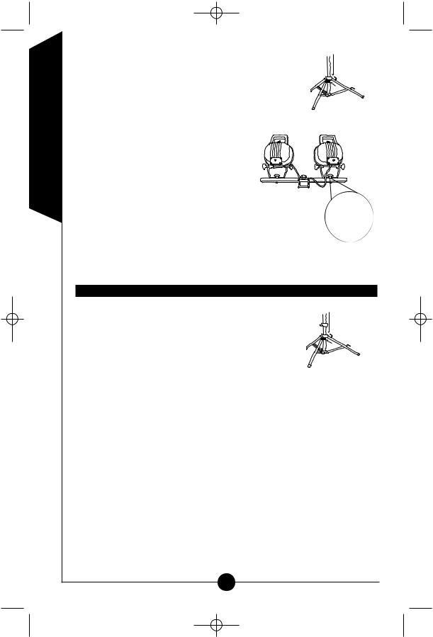
Replacing the bulb:
NOTE: Always handle halogen bulbs with gloves or with a clean soft cloth. Oil from your skin can cause premature failure of the bulb.
Step 1: Make sure fixture is turned OFF and unplugged. |
Fig. D |
Step 2: Loosen the plastic knob on the back on the fixture |
SPARE BULB |
door (figure D). |
|
Step 3: The door frame and lens assembly will swing |
|
down allowing access to the bulb. |
|
NOTE: Each fixture contains one 500-watt and one 250-  watt bulb. The smaller socket accepts a 250-watt max bulb and the larger socket accepts a 500-watt max bulb.
Step 4: Using gloves or soft cloth, press the old bulb to one side of the spring loaded socket as indicated on the metal reflector. Remove opposite end of bulb from the other side of
the socket. Remove the new bulb from its package making sure not to touch bulb with
bare hands. Reverse this procedure to install
a new replacement bulb (figure E).
Step 5: Replace the door frame and lens assembly and secure it using the plastic knob.
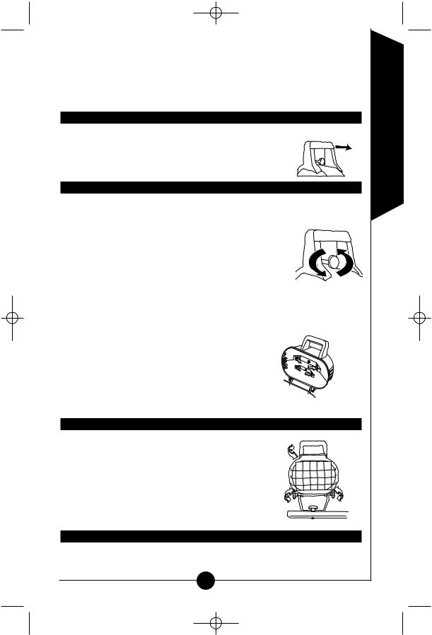
Aiming the fixture:
Make sure the light fixture is in the OFF position and cool. Loosen the knobs located on the side of the light fixture housing. Using the top carrying handle tilt to desired position then retighten knobs (figure F). There is a stop that restricts the downward movement of the fixture for your safety. To prevent overheating and risk of burns or fire, do not aim the fixture down at an angle of more than 10 degrees from horizontal.
Two Year Limited Warranty:
Cooper Lighting (“the Company”) warrants this product (“the product”) against defects in material or workmanship for a period of two years from
5
ENGLISH
WZT1500 I.S. 325-1394 10/28/03 3:42 PM Page 6
ENGLISH
date of original purchase, and agrees to repair or, at the Company’s option, replace a defective product without charge for either replacement parts or labor during such time. This does not include labor to remove or install fixtures.
This warranty is extended only to the original purchaser of the product. A purchasers receipt or other proof of date of original purchase acceptable to the Company is required before warranty performance shall be rendered.
This warranty only covers product failure due to defects in materials or workmanship which occurs in normal use. It does not cover the bulb or failure of the product caused by accident, misuse, abuse, lack of reasonable care, alteration, or faulty installation, subjecting the product to any but the specified electrical service or any other failure not resulting from defects in materials or workmanship. Damage to the product caused by separately purchased, non-Company brand replacement bulbs and corrosion or discoloration of brass components are not covered by this warranty.
There are no express warranties except as described above.
THE COMPANY SHALL NOT BE LIABLE FOR INCIDENTAL, SPECIAL OR CONSEQUENTIAL DAMAGES RESULTING FROM THE USE OF THE PRODUCT OR ARISING OUT OF ANY BREACH OF THIS WARRANTY. ALL IMPLIED WARRANTIES, IF ANY, INCLUDING IMPLIED WARRANTIES OF MERCHANTABILITY AND FITNESS FOR A PARTICULAR PURPOSE, ARE LIMITED IN DURATION TO THE DURATION OF THIS EXPRESS WARRANTY. Some states do not allow the exclusion or limitation of incidental or consequential damages, or limitations on how long an implied warranty lasts, so the above exclusions or limitations may not apply to you.
No other warranty, written or verbal, is authorized by the Company. This warranty gives you specific legal rights, and you may also have other rights which vary from state to state.
To obtain warranty service, please write to Cooper Lighting, 1121 Highway 74 South, Peachtree City, GA 30269. Enclose product model number and problems you are experiencing, along with your address and telephone number. You will then be contacted with a solution, or a Return Goods Authorization number and full instructions for returning the product. All returned products must be accompanied by a Return Goods Authorization Number issued by the Company and must be returned freight prepaid. Any product received without a Return Goods Authorization Number from the Company will be refused.
Cooper Lighting is not responsible for merchandise damaged in transit. Repaired or replaced products shall be subject to the terms of this warranty and are inspected when packed. Evident or concealed damage that is made in transit should be reported at once to the carrier making the delivery and a claim filed with them.
Customer First Center • 1121 Highway 74 South, Peachtree City, GA 30269 USA www.cooperlighting.com
© 2003 Cooper Lighting
Reproductions of this document without prior written approval of Cooper Lighting are strictly prohibited.
6
 Loading...