


 Loading...
b
Hardware and Software
Guide
Compaq Notebook Series
Document Part Number: 383110-001
May 2005
This guide explains how to identify, access, and use the hardware and software features available on your notebook.
© Copyright 2005 Hewlett-Packard Development Company, L.P.
Microsoft and Windows are U.S. registered trademarks of Microsoft Corporation. SD Logo is a trademark of its proprietor. Bluetooth is a trademark owned by its proprietor and used by Hewlett-Packard Company under license. Adobe and Acrobat are trademarks of Adobe Systems Incorporated.
The information contained herein is subject to change without notice. The only warranties for HP products and services are set forth in the express warranty statements accompanying such products and services. Nothing herein should be construed as constituting an additional warranty. HP shall not be liable for technical or editorial errors or omissions contained herein.
Hardware and Software Guide
Compaq Notebook Series
First Edition May 2005
Reference Number: M2000
Document Part Number: 383110-001

Contents
1 Hardware
Top Components . . . . . . . . . . . . . . . . . . . . . . . . . . . . . . . 1–1
Keys. . . . . . . . . . . . . . . . . . . . . . . . . . . . . . . . . . . . . . 1–1
TouchPad . . . . . . . . . . . . . . . . . . . . . . . . . . . . . . . . . . 1–3
Power Controls . . . . . . . . . . . . . . . . . . . . . . . . . . . . . 1–4
Lights. . . . . . . . . . . . . . . . . . . . . . . . . . . . . . . . . . . . . 1–5
Wireless (Select Models Only) and
Volume Buttons. . . . . . . . . . . . . . . . . . . . . . . . . . . . . 1–7
Antennae (Select Models Only) . . . . . . . . . . . . . . . . 1–8
Front Components . . . . . . . . . . . . . . . . . . . . . . . . . . . . . . 1–9
Lights. . . . . . . . . . . . . . . . . . . . . . . . . . . . . . . . . . . . . 1–9
Speakers, Jacks and Display Release Button. . . . . . 1–10
Rear Components. . . . . . . . . . . . . . . . . . . . . . . . . . . . . . 1–11
Left-Side Components . . . . . . . . . . . . . . . . . . . . . . . . . . 1–12
Ports and Jacks. . . . . . . . . . . . . . . . . . . . . . . . . . . . . 1–12
PC Card Slot and Button . . . . . . . . . . . . . . . . . . . . . 1–13
Right-Side Components . . . . . . . . . . . . . . . . . . . . . . . . . 1–14
Bottom Components. . . . . . . . . . . . . . . . . . . . . . . . . . . . 1–16
Mini PCI and Memory Compartments . . . . . . . . . . 1–16
Bays, Battery Latch and Vents . . . . . . . . . . . . . . . . 1–17
Additional Components . . . . . . . . . . . . . . . . . . . . . . . . . 1–18
Hardware . . . . . . . . . . . . . . . . . . . . . . . . . . . . . . . . . 1–18
Optical Discs . . . . . . . . . . . . . . . . . . . . . . . . . . . . . . 1–19
Labels. . . . . . . . . . . . . . . . . . . . . . . . . . . . . . . . . . . . 1–20
Hardware and Software Guide |
iii |

Contents
2 TouchPad and Keyboard
TouchPad . . . . . . . . . . . . . . . . . . . . . . . . . . . . . . . . . . . . . 2–1
Identifying TouchPad Components. . . . . . . . . . . . . . 2–1
Using the TouchPad. . . . . . . . . . . . . . . . . . . . . . . . . . 2–2
Setting TouchPad Preferences . . . . . . . . . . . . . . . . . . 2–3
Hotkeys . . . . . . . . . . . . . . . . . . . . . . . . . . . . . . . . . . . . . . 2–5
Identifying Hotkeys . . . . . . . . . . . . . . . . . . . . . . . . . . 2–5
Hotkey Quick Reference . . . . . . . . . . . . . . . . . . . . . . 2–6
Using Hotkey Procedures . . . . . . . . . . . . . . . . . . . . . 2–7
Using Hotkey Commands . . . . . . . . . . . . . . . . . . . . . 2–8
Keypads . . . . . . . . . . . . . . . . . . . . . . . . . . . . . . . . . . . . . 2–14
Using the Embedded Numeric Keypad . . . . . . . . . . 2–15
Using an External Numeric Keypad . . . . . . . . . . . . 2–18
3 Power
Power Sources . . . . . . . . . . . . . . . . . . . . . . . . . . . . . . . . . 3–1 Selecting a Power Source . . . . . . . . . . . . . . . . . . . . . 3–1 Switching Between Battery and
External Power . . . . . . . . . . . . . . . . . . . . . . . . . . . . . 3–3 Power Control and Light Locations . . . . . . . . . . . . . . . . . 3–4 Standby, Hibernation and Shutdown Overviews . . . . . . . 3–5 Standby . . . . . . . . . . . . . . . . . . . . . . . . . . . . . . . . . . . 3–5 Hibernation . . . . . . . . . . . . . . . . . . . . . . . . . . . . . . . . 3–6 Leaving Your Work. . . . . . . . . . . . . . . . . . . . . . . . . . 3–7 Interference with Drive Media . . . . . . . . . . . . . . . . . 3–7 Standby, Hibernation and Shutdown Procedures. . . . . . . 3–8 Turning the Notebook On or Off. . . . . . . . . . . . . . . . 3–8 Initiating or Resuming from Standby . . . . . . . . . . . . 3–9 Initiating or Restoring from Hibernation. . . . . . . . . 3–10 Using Emergency Shutdown Procedures . . . . . . . . 3–11 Power Preferences . . . . . . . . . . . . . . . . . . . . . . . . . . . . . 3–12 Using Power Schemes . . . . . . . . . . . . . . . . . . . . . . . 3–12 Prompting for Standby Password . . . . . . . . . . . . . . 3–12 Setting Other Power Preferences. . . . . . . . . . . . . . . 3–13
iv |
Hardware and Software Guide |

Contents
Battery Pack . . . . . . . . . . . . . . . . . . . . . . . . . . . . . . . . . . 3–14 Charging a Battery Pack . . . . . . . . . . . . . . . . . . . . . 3–14 Monitoring the Charge in a Battery Pack . . . . . . . . 3–15 Managing Low-Battery Conditions. . . . . . . . . . . . . 3–16 Calibrating a Battery Pack. . . . . . . . . . . . . . . . . . . . 3–18 Conserving Battery Pack Power . . . . . . . . . . . . . . . 3–22 Replacing a Battery Pack. . . . . . . . . . . . . . . . . . . . . 3–23 Storing a Battery Pack . . . . . . . . . . . . . . . . . . . . . . . 3–26
Disposing of a Used Battery Pack . . . . . . . . . . . . . . . . . 3–26
4 Multimedia
Internal Speakers . . . . . . . . . . . . . . . . . . . . . . . . . . . . . . . 4–1 Volume Controls . . . . . . . . . . . . . . . . . . . . . . . . . . . . . . . 4–2 External Audio Devices . . . . . . . . . . . . . . . . . . . . . . . . . . 4–3 Using the Audio-Out (Headphone) Jack . . . . . . . . . . 4–3 Using the Audio-In (Microphone) Jack. . . . . . . . . . . 4–4 External Video Devices . . . . . . . . . . . . . . . . . . . . . . . . . . 4–4
Connecting an S-Video Device
(Select Models Only). . . . . . . . . . . . . . . . . . . . . . . . . 4–4 Displaying a Video Image . . . . . . . . . . . . . . . . . . . . . 4–6 CD and DVD Procedures . . . . . . . . . . . . . . . . . . . . . . . . . 4–6 Inserting or Removing a Disc . . . . . . . . . . . . . . . . . . 4–6 Using Media Activity Hotkeys . . . . . . . . . . . . . . . . . 4–8 Setting AutoPlay Preferences . . . . . . . . . . . . . . . . . . 4–9 Protecting Playback . . . . . . . . . . . . . . . . . . . . . . . . . 4–10 Protecting a CD or DVD Write Process . . . . . . . . . 4–10 Multimedia Software . . . . . . . . . . . . . . . . . . . . . . . . . . . 4–11 Observing the Copyright Warning . . . . . . . . . . . . . 4–12 Installing Software. . . . . . . . . . . . . . . . . . . . . . . . . . 4–13 Enabling AutoPlay. . . . . . . . . . . . . . . . . . . . . . . . . . 4–14 Changing DVD Region Settings . . . . . . . . . . . . . . . 4–14
Hardware and Software Guide |
v |

Contents
5Wireless
(Select Models Only)
Wireless Features . . . . . . . . . . . . . . . . . . . . . . . . . . . . . . . 5–1 Wireless Controls. . . . . . . . . . . . . . . . . . . . . . . . . . . . . . . 5–2 802.11 Wireless Devices (Select Models Only) . . . . . . . 5–3 Setting Up a WLAN in Your Home . . . . . . . . . . . . . 5–4 Connecting to a WLAN in Your Home. . . . . . . . . . . 5–5 Connecting to a Public WLAN . . . . . . . . . . . . . . . . . 5–6 Using Wireless Security Features . . . . . . . . . . . . . . . 5–6 Identifying an 802.11 Wireless Device . . . . . . . . . . . 5–7 Troubleshooting Devices. . . . . . . . . . . . . . . . . . . . . . 5–7 Bluetooth Wireless Devices (Select Models Only) . . . . . 5–8 Wireless Device Power States . . . . . . . . . . . . . . . . . . . . 5–10 Turning On the Devices. . . . . . . . . . . . . . . . . . . . . . 5–12 Turning Off and Disabling the Devices. . . . . . . . . . 5–13
6 Security
Security Features . . . . . . . . . . . . . . . . . . . . . . . . . . . . . . . 6–1 QuickLock . . . . . . . . . . . . . . . . . . . . . . . . . . . . . . . . . . . . 6–3 Setup Utility and Windows Passwords . . . . . . . . . . . . . . 6–3 Coordinating Passwords . . . . . . . . . . . . . . . . . . . . . . 6–5 Choosing a Password. . . . . . . . . . . . . . . . . . . . . . . . . 6–5 Setup Utility Administrator Password . . . . . . . . . . . . . . . 6–6 Setting an Administrator Password . . . . . . . . . . . . . . 6–7 Entering an Administrator Password. . . . . . . . . . . . . 6–7 Setup Utility Power-On Password . . . . . . . . . . . . . . . . . . 6–8 Setting a Power-On Password . . . . . . . . . . . . . . . . . . 6–9 Entering a Power-On Password. . . . . . . . . . . . . . . . . 6–9 Setup Utility Device Security. . . . . . . . . . . . . . . . . . . . . 6–10 Antivirus Software . . . . . . . . . . . . . . . . . . . . . . . . . . . . . 6–11 Critical Security Updates for Windows XP . . . . . . . . . . 6–12 Firewall Software. . . . . . . . . . . . . . . . . . . . . . . . . . . . . . 6–13 Optional Security Cable . . . . . . . . . . . . . . . . . . . . . . . . . 6–14
vi |
Hardware and Software Guide |

Contents
7 Hardware Upgrades and Replacements
Device Connections . . . . . . . . . . . . . . . . . . . . . . . . . . . . . 7–1 Connecting a Powered Device. . . . . . . . . . . . . . . . . . 7–1 Connecting a USB Device. . . . . . . . . . . . . . . . . . . . . 7–2 Connecting a 1394 Device
(Select Models Only). . . . . . . . . . . . . . . . . . . . . . . . . 7–3 Connecting a Communication Device. . . . . . . . . . . . 7–4 Digital Memory Cards . . . . . . . . . . . . . . . . . . . . . . . . . . . 7–4 Using the Memory Reader Light . . . . . . . . . . . . . . . . 7–5 Inserting a Digital Memory Card. . . . . . . . . . . . . . . . 7–6 Removing a Digital Memory Card . . . . . . . . . . . . . . 7–7 PC Cards. . . . . . . . . . . . . . . . . . . . . . . . . . . . . . . . . . . . . . 7–8 Inserting a PC Card . . . . . . . . . . . . . . . . . . . . . . . . . . 7–9 Stopping or Removing a PC Card . . . . . . . . . . . . . . 7–10 Drives . . . . . . . . . . . . . . . . . . . . . . . . . . . . . . . . . . . . . . . 7–11 Adding a Drive to the System . . . . . . . . . . . . . . . . . 7–11 Using the IDE Drive Light . . . . . . . . . . . . . . . . . . . 7–11 Caring for Drives . . . . . . . . . . . . . . . . . . . . . . . . . . . 7–12 Replacing the Internal Hard Drive. . . . . . . . . . . . . . 7–13 Memory . . . . . . . . . . . . . . . . . . . . . . . . . . . . . . . . . . . . . 7–17 Increasing Memory . . . . . . . . . . . . . . . . . . . . . . . . . 7–17 Removing or Inserting a Memory Module . . . . . . . 7–18
8Software Updates and Recoveries and System Software
Software Updates . . . . . . . . . . . . . . . . . . . . . . . . . . . . . . . 8–1 Preparing for a Software Update . . . . . . . . . . . . . . . . 8–2 Downloading and Installing an Update . . . . . . . . . . . 8–4 Software Recoveries. . . . . . . . . . . . . . . . . . . . . . . . . . . . . 8–8 Using System Restore . . . . . . . . . . . . . . . . . . . . . . . . 8–8 Repairing or Reinstalling Software . . . . . . . . . . . . . . 8–9
Hardware and Software Guide |
vii |

Contents
Setup Utility . . . . . . . . . . . . . . . . . . . . . . . . . . . . . . . . . . . 8–9 Opening the Setup Utility . . . . . . . . . . . . . . . . . . . . . 8–9 Changing the Language of the Setup Utility . . . . . . 8–10 Navigating and Selecting in the Setup Utility . . . . . 8–10 Displaying System Information. . . . . . . . . . . . . . . . 8–11 Restoring Default Settings in the Setup Utility . . . . 8–12 Using Advanced Setup Utility Features . . . . . . . . . 8–13 Closing the Setup Utility . . . . . . . . . . . . . . . . . . . . . 8–14
A Specifications
Operating Environment . . . . . . . . . . . . . . . . . . . . . . . . . . A–1
Rated Input Power . . . . . . . . . . . . . . . . . . . . . . . . . . . . . . A–2
Expansion Port Input/Output Signals. . . . . . . . . . . . . . . . A–3
Index
viii |
Hardware and Software Guide |

1
Hardware
Top Components
Keys
Component |
Description |
|
|
|
|
1 |
Function keys (12) |
Perform system and application tasks. |
|
|
When combined with fn, the function |
|
|
keys perform additional tasks as |
|
|
hotkeys. |
|
|
|
2 |
Windows logo key |
Displays the Microsoft® Windows® |
|
|
Start menu. |
(Continued)
Hardware and Software Guide |
1–1 |

Hardware
Component |
Description |
|
|
|
|
3 |
fn key |
Combines with other keys to perform |
|
|
system tasks. For example, pressing |
|
|
fn+f7 decreases screen brightness. |
|
|
|
4 |
Keypad keys (15) |
Can be used like the keys on an |
|
|
external numeric keypad. |
|
|
|
5 |
Windows applications key |
Displays a shortcut menu for items |
|
|
beneath the pointer. |
|
|
|
1–2 |
Hardware and Software Guide |
Hardware
TouchPad
Component |
Description |
|
|
|
|
1 |
TouchPad* |
Moves the pointer. |
|
|
|
2 |
Left TouchPad button* |
Functions like the left button on an |
|
|
external mouse. |
|
|
|
3 |
Right TouchPad button* |
Functions like the right button on an |
|
|
external mouse. |
|
|
|
4 |
TouchPad vertical and |
Scrolls upward or downward, or left |
|
horizontal scrolling regions* |
or right. |
*This table describes default settings. For information about changing the functions of TouchPad components, refer to the “Setting TouchPad Preferences” section in Chapter 2, “TouchPad and Keyboard.”
Hardware and Software Guide |
1–3 |

Hardware
Power Controls
Component |
Description |
|
|
|
|
1 |
Display switch* |
If the notebook is closed while on, initiates |
|
|
standby. |
|
|
|
2 |
Power/standby button* |
When the notebook is |
|
|
■ Off, press to turn on the notebook. |
|
|
■ On, briefly press to initiate hibernation. |
|
|
■ In standby, briefly press to resume from |
standby.
■ In hibernation, briefly press to restore from hibernation.
If the system has stopped responding and Windows shutdown procedures cannot be used, press and hold for at least 4 seconds to turn off the notebook.
*This table describes default settings. For information about changing the function of the display switch or power/standby button, refer to the “Setting Other Power Preferences” section in Chapter 3, “Power.”
1–4 |
Hardware and Software Guide |

Hardware
Lights
Component |
Description |
|
|
|
|
1 |
Caps lock light |
On: Caps lock is on. |
|
|
|
2 |
Wireless light |
On: One or more optional internal wireless |
|
(select models only)* |
devices, such as a WLAN and/or a |
|
|
Bluetooth® device (select models only), |
|
|
are turned on. |
|
|
|
3 |
Power/standby light† |
On: Notebook is turned on. |
|
|
Blinking: Notebook is in standby. |
|
|
Off: Notebook is off. |
(Continued)
Hardware and Software Guide |
1–5 |

Hardware
Component |
Description |
|
|
|
|
4 |
Mute light |
On: Volume is muted. |
|
|
|
5 |
Num lock light |
On: Num lock or the embedded numeric |
|
|
keypad is on. |
*For information about establishing a wireless connection, refer to Chapter 5, “Wireless (Select Models Only).”
†The notebook has 2 power/standby lights. The power/standby light on the top of the notebook is visible only when the notebook is open; the power/standby light on the front of the notebook is visible whether
the notebook is open or closed.
1–6 |
Hardware and Software Guide |

Hardware
Wireless (Select Models Only) and
Volume Buttons
Component |
Description |
|
|
|
|
1 |
Wireless button |
Turns the wireless functionality on or |
|
(select models only) |
off but does not create a wireless |
|
|
connection. |
|
|
To establish a wireless |
|
|
connection, a wireless network |
|
|
must already be set up. For |
|
|
information about establishing |
|
|
a wireless connection, refer to |
|
|
Chapter 5, “Wireless (Select |
|
|
Models Only).” |
|
|
|
2 |
Volume down button |
Decreases system volume. |
|
|
|
3 |
Volume up button |
Increases system volume. |
|
|
|
4 |
Volume mute button |
Mutes or restores volume. |
|
|
|
Hardware and Software Guide |
1–7 |

Hardware
Antennae (Select Models Only)
Component |
Description |
|
|
Antennae (2)* |
Send and receive wireless device signals. |
|
Å Exposure to Radio Frequency |
|
Radiation. The radiated output |
|
power of this device is below the |
|
FCC radio frequency exposure limits. |
|
Nevertheless, the device should be |
|
used in such a manner that the |
|
potential for human contact during |
|
normal operation is minimized. To |
|
avoid the possibility of exceeding |
|
the FCC radio frequency exposure |
|
limits, human proximity to the |
|
antennae should be not less than |
|
20 cm (8 inches) during normal |
|
operation, including when the |
|
notebook display is closed. |
*The antennae (select models only) are not visible from the outside of the notebook. For optimal transmission, keep the areas immediately around the antennae free from obstructions.
1–8 |
Hardware and Software Guide |
Hardware
Front Components
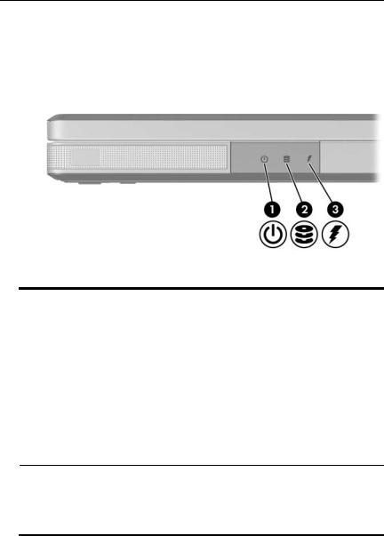
Lights
Component |
Description |
|
|
|
|
1 |
Power/standby light* |
On: Notebook is turned on. |
|
|
Blinking: Notebook is in standby. |
|
|
Off: Notebook is off. |
|
|
|
2 |
IDE (Integrated Drive |
On or blinking: The internal hard drive |
|
Electronics) drive light |
or an optical drive is being accessed. |
|
|
|
3 |
Battery light |
On: The battery pack is charging. |
|
|
Blinking: The battery pack has |
|
|
reached a low-battery condition. |
Off: The battery pack is fully charged or not inserted.
*The light on the power/standby button and the power/standby light on the front of the notebook display the same information. The light on the power/standby button is visible when the notebook is open; the power/standby light on the front of the notebook is visible whether the notebook is open or closed.
Hardware and Software Guide |
1–9 |
Hardware
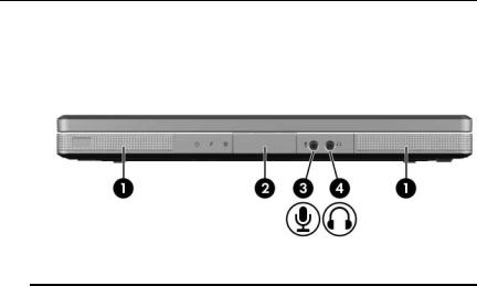
Speakers, Jacks and Display Release Button
Component |
Description |
|
|
|
|
1 |
Stereo speakers (2) |
Produce stereo sound. |
|
|
|
2 |
Display release button |
Opens the notebook. |
|
|
|
3 |
Audio-in |
Connects an optional monaural (single |
|
(microphone) jack |
sound channel) microphone. |
|
|
|
4 |
Audio-out |
Connects optional headphones or |
|
(headphone) jack |
powered stereo speakers. Also connects |
|
|
the audio function of an audio/video |
|
|
device such as a television or VCR. |
|
|
|
1–10 |
Hardware and Software Guide |

Hardware
Rear Components
Component |
Description |
|
|
Exhaust vent* |
Provides airflow to cool internal |
|
components. |
|
Ä To prevent overheating, do not |
|
obstruct vents. Do not allow a |
|
hard surface, such as a printer, |
|
or a soft surface, such as pillows |
|
or thick rugs or clothing, to block |
|
airflow. |
*The notebook has 4 vents. This and all other vents are visible on the bottom of the notebook. One vent is also visible on the left side of the notebook.
Hardware and Software Guide |
1–11 |

Hardware
Left-Side Components
Ports and Jacks
Component |
Description |
||
|
|
|
|
1 |
Power connector |
Connects the AC adapter cable. |
|
|
|
|
|
2 |
Monitor port |
Connects an optional VGA monitor or |
|
|
|
|
projector. |
|
|
|
|
3 |
Expansion Port 2 |
Connects the notebook to an optional |
|
|
(select models only)*† |
docking device. |
|
4 |
RJ-45 |
(network) jack |
Connects an optional network cable. |
|
|
|
|
5 |
RJ-11 |
(modem) jack |
Connects the modem cable. |
|
|
|
|
6 |
USB port‡ |
Connects an optional USB device. |
|
*The notebook has only one expansion port. The term Expansion Port 2 describes the type of expansion port.
†For expansion port signal information, refer to the “Expansion Port Input/Output Signals” section.
‡Depending on the model, the notebook has 2 or 3 USB ports. The other USB ports are on the right side of the notebook.
1–12 |
Hardware and Software Guide |
Hardware
PC Card Slot and Button
Component |
Description |
|
|
|
|
1 |
PC Card slot |
Supports an optional Type I or Type II |
|
|
32-bit (CardBus) or 16-bit PC Card. |
|
|
|
2 |
PC Card eject button |
Ejects an optional PC Card from the |
|
|
PC Card slot. |
|
|
|
Hardware and Software Guide |
1–13 |

Hardware
Right-Side Components
Component |
Description |
|
|
|
|
1 |
USB ports (1 or 2 depending |
Connect optional USB devices. |
|
on the notebook model)* |
|
|
|
|
2 |
Memory Reader |
Supports an optional digital |
|
(select models only) |
memory card.† |
3 |
1394 port |
Connects an optional 1394a device |
|
(select models only) |
such as a scanner, a digital camera, |
|
|
or a digital camcorder. |
|
|
|
4 |
Memory Reader light |
On: An optional digital memory card is |
|
(select models only) |
being accessed. |
|
|
|
5 |
Optical drive‡ |
Supports an optical disc. |
(Continued)
1–14 |
Hardware and Software Guide |

|
|
|
Hardware |
|
|
|
|
|
|
|
|
|
Component |
Description |
|
|
|
|
|
6 |
S-Video-out jack |
Connects an optional S-Video device |
|
|
|
(select models only) |
such as a television, VCR, camcorder, |
|
|
|
projector, or video capture card. |
|
|
|
|
7 |
Security cable slot |
Attaches an optional security cable to |
|
|
|
|
the notebook. |
Ä Security solutions are designed to act as deterrents. These deterrents may not prevent a product from being mishandled or stolen.
*Depending on the model, the notebook has 2 or 3 USB ports. The other USB port is on the left side.
†The digital memory card could be a Secure Digital (SD) Memory Card, Memory Stick, Memory Stick Pro, xD-Picture Card, MultiMediaCard, or SmartMedia (SM) card.
‡The type of optical drive—for example, a DVD-ROM drive, a DVD/CD-RW Combo Drive, or a DVD+R/RW and CD-RW Combo Drive—varies by notebook model.
Hardware and Software Guide |
1–15 |

Hardware
Bottom Components
Mini PCI and Memory Compartments
Component |
Description |
|
|
1 Mini PCI |
Holds an optional wireless LAN device. |
compartment |
Ä To prevent an unresponsive system and |
|
|
|
the display of a warning message, |
|
install only a Mini PCI device authorized |
|
for use in your notebook by the |
|
governmental agency that regulates |
|
wireless devices in your country. If you |
|
install an unauthorized device and then |
|
receive a warning message, remove the |
|
device to restore notebook functionality. |
|
Then contact Customer Care. |
|
|
2 Memory |
Contains 2 memory slots that support |
compartment |
replaceable memory modules. The number |
|
of preinstalled memory modules varies by |
|
notebook model. |
|
|
1–16 |
Hardware and Software Guide |

Hardware
Bays, Battery Latch and Vents
Component |
Description |
|
|
|
|
1 |
Battery bay |
Holds a battery pack. |
|
|
|
2 |
Battery pack release latch |
Releases a battery pack from the |
|
|
battery bay.* |
|
|
|
3 |
Exhaust vents (4)† |
Provide airflow to cool internal |
|
|
components. |
|
|
Ä To prevent overheating, do not |
|
|
obstruct vents. Do not allow a hard |
|
|
surface, such as a printer, or a soft |
|
|
surface, such as pillows or thick |
|
|
rugs or clothing, to block airflow. |
|
|
|
4 |
Hard drive bay |
Holds the internal hard drive. |
*Battery packs vary by model.
†The notebook has 4 vents. One vent is also visible on the rear of the notebook.
Hardware and Software Guide |
1–17 |
Hardware
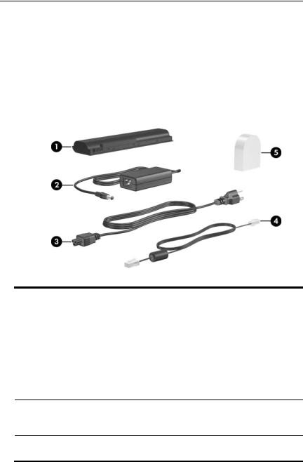
Additional Components
Hardware
The components included with your notebook vary by region, country, notebook model, and the optional hardware you purchased. The following sections identify the standard external components included with most notebook models.
Component |
Description |
|
|
|
|
1 |
Battery pack* |
Powers the notebook when the notebook is |
|
|
not connected to external power. |
|
|
|
2 |
AC adapter |
Converts AC power to DC power. |
|
|
|
3 |
Power cord* |
Connects an AC adapter to an AC outlet. |
|
|
|
4 |
Modem cable* |
Connects a modem to an RJ-11 telephone |
|
|
jack or to a country-specific modem |
|
|
adapter. |
5Country-specific modem adapter (included by region as required)*
Adapts the modem cable to a non-RJ-11 (modem) jack.
*Battery packs vary by model. Power cords, modem cables, and modem adapters vary in appearance by region and country.
1–18 |
Hardware and Software Guide |

Hardware
Optical Discs
Software on optical discs, such as CDs or DVDs, is included with all notebook models.
The software applications packaged in the Required for Setup bag are not preinstalled on your notebook. Depending on how you want to use your notebook, you may want to install some or all of these applications.
The software applications packaged in the Save for Later bag are preinstalled or preloaded on your notebook. The software discs are provided in case you ever need to repair or reinstall this software.
Additional discs packaged with your notebook provide operating system recovery software and driver recovery software. Application recovery software is provided with select notebook models.
The User Guides CD contains Adobe® Acrobat® PDF files, not software. The files on the User Guides CD are not preinstalled or preloaded on your notebook.
Hardware and Software Guide |
1–19 |

Hardware
Labels
The labels affixed to the notebook provide information you may need when you troubleshoot system problems or travel internationally with the notebook.
■Service Tag—Provides the product name, product number (P/N), and serial number (S/N) of your notebook. You may need the product number and the serial number when you contact Customer Care. The Service Tag label is affixed to the bottom of the notebook. To display the information on the Service Tag on your screen, select Start > Help and Support.
■Microsoft Certificate of Authenticity—Contains the Microsoft® Windows® Product Key. You may need the Product Key to update or troubleshoot the operating system. This certificate is affixed to the bottom of the notebook.
■Regulatory label—Provides regulatory information about the notebook. The Regulatory label is affixed to the inside of the battery bay.
■Modem Approval label—Provides regulatory information about the modem and lists the agency approval markings required by some of the countries in which the modem has been approved for use. You may need this information when traveling internationally. The Modem Approval label is affixed to the inside of the memory compartment cover.
■Wireless certification labels—Some notebook models include an optional WLAN device and/or an optional Bluetooth® device. If your notebook model includes one or more wireless devices, a certificate providing regulatory information about each device and the approval markings of some of the countries in which the device has been approved for use is included with your notebook. You may need this information when traveling internationally. Wireless certification labels are affixed to the inside of the Mini PCI compartment cover.
1–20 |
Hardware and Software Guide |

2
TouchPad and Keyboard
TouchPad
Identifying TouchPad Components
The TouchPad includes the following components:
1 |
TouchPad |
3 |
Right TouchPad button |
2 |
Left TouchPad button |
4 |
TouchPad vertical and |
|
|
|
horizontal scrolling regions |
Hardware and Software Guide |
2–1 |

TouchPad and Keyboard
Using the TouchPad
The TouchPad provides the navigation, selection, and scroll functions of an optional external mouse:
■To move the pointer, slide your finger across the TouchPad surface in the direction you want to move the pointer.
■To execute the click functions of the left or right button on an external mouse, press the left or right TouchPad button.
■To scroll, place your finger onto a scrolling region, and then slide your finger along the scrolling region in the direction you want to scroll. (Sliding your finger from the TouchPad to a scrolling region without first lifting your finger from the TouchPad and then placing it on the scrolling region will not activate the scrolling region.)
The TouchPad is enabled when the notebook is turned on. If you work with keystrokes rather than mouse actions, you may prefer to disable the TouchPad to prevent accidental TouchPad activity.
2–2 |
Hardware and Software Guide |
Loading...