


Maintenance &
Service Guide
Compaq Deskpro EX and Deskpro EXS
Series of Personal Computers
Minitower Models

Maintenance &
Service Guide
Compaq Deskpro EX and Deskpro EXS
Series of Personal Computers
Minitower Models
Notice
© 2000 Compaq Computer Corporation. Except for use in connection with the accompanying Compaq product, no part of this guide may be photocopied or reproduced in any form without prior written consent from Compaq Computer Corporation.
COMPAQ, the Compaq logo, and Deskpro Registered in U.S. Patent and Trademark Office are trademarks of Compaq Information Technologies Group, L.P.
Microsoft, Windows, Windows NT, and other names of Microsoft products referenced herein are trademarks or registered trademarks of Microsoft Corporation.
Intel and Pentium are registered trademarks of Intel Corporation. Celeron and MMX are trademarks of Intel Corporation.
All other product names mentioned herein may be trademarks or registered trademarks of their respective companies.
Compaq shall not be liable for technical or editorial errors or omissions contained herein. The information in this document is subject to change without notice.
THE INFORMATION IN THIS PUBLICATION IS PROVIDED "AS IS" WITHOUT WARRANTY OF ANY KIND. THE ENTIRE RISK ARISING OUT OF THE USE OF THIS INFORMATION REMAINS WITH RECIPIENT. IN NO EVENT SHALL COMPAQ BE LIABLE FOR ANY DIRECT, CONSEQUENTIAL, INCIDENTAL, SPECIAL, PUNITIVE OR OTHER DAMAGES WHATSOEVER (INCLUDING WITHOUT LIMITATION, DAMAGES FOR LOSS OF BUSINESS PROFITS, BUSINESS INTERRUPTION OR LOSS OF BUSINESS INFORMATION), EVEN IF COMPAQ HAS BEEN ADVISED OF THE POSSIBILITY OF SUCH DAMAGES AND WHETHER IN AN ACTION OF CONTRACT OR TORT, INCLUDING NEGLIGENCE.
The limited warranties for Compaq products are exclusively set forth in the documentation accompanying such products. Nothing herein should be construed as constituting a further or additional warranty.
The following words and symbols mark special messages throughout this guide:
WARNING: Text set off in this manner indicates that failure to follow directions could result in bodily harm or loss of life.
CAUTION: Text set off in this manner indicates that failure to follow directions could result in damage to equipment or loss of information.
Maintenance & Service Guide
Compaq Deskpro EX and Deskpro EXS Series of Personal Computers
Minitower Models
First Edition (September 2000)
Part Number 201856-001
Spare Parts Number 215879-001
Compaq Computer Corporation

CONTENTS
preface
About This Guide
Symbols and Conventions ......................................................................................................... |
vii |
Technician Notes....................................................................................................................... |
vii |
Locating Additional Information ............................................................................................. |
viii |
chapter 1
Product Description
1.1 |
Computer Features.......................................................................................................... |
1-2 |
|
|
1.1.1 Front Panel Controls and LEDs ......................................................................... |
1-2 |
|
|
1.1.2 |
Rear Panel Connectors ....................................................................................... |
1-3 |
|
1.1.3 |
Drive Positions ................................................................................................... |
1-4 |
1.2 |
Serial Number Location.................................................................................................. |
1-5 |
|
chapter 2
Spare Parts
2.1 |
System Unit .................................................................................................................... |
2-2 |
2.2 |
Mass Storage Devices..................................................................................................... |
2-3 |
2.3 |
Cables ............................................................................................................................. |
2-4 |
2.4 |
Standard, Memory, and Expansion Boards .................................................................... |
2-5 |
2.5 |
Miscellaneous Plastics Kit .............................................................................................. |
2-6 |
2.6 |
Keyboards (not illustrated) ............................................................................................. |
2-7 |
2.7 |
Miscellaneous Screw Kit (not illustrated)....................................................................... |
2-7 |
2.8 |
Miscellaneous Parts (not illustrated)............................................................................... |
2-8 |
2.9 |
Shipping Boxes (not illustrated) ..................................................................................... |
2-8 |
2.10 |
Documentation and Software (not illustrated) ................................................................ |
2-8 |
chapter 3
Removal and Replacement Preliminaries
3.1 |
Electrostatic Discharge Information ............................................................................... |
3-1 |
|
|
3.1.1 |
Generating Static ................................................................................................ |
3-1 |
|
3.1.2 Preventing Electrostatic Damage to Equipment................................................. |
3-2 |
|
|
3.1.3 Personal Grounding Methods and Equipment ................................................... |
3-2 |
|
|
3.1.4 |
Grounding Workstations .................................................................................... |
3-2 |
|
3.1.5 Recommended Materials and Equipment........................................................... |
3-3 |
|
3.2 |
Routine Care ................................................................................................................... |
3-3 |
|
|
3.2.1 General Cleaning Safety Precautions ................................................................. |
3-3 |
|
|
3.2.2 Cleaning the Computer Case.............................................................................. |
3-4 |
|
|
3.2.3 |
Cleaning the Keyboard....................................................................................... |
3-4 |
|
3.2.4 |
Cleaning the Monitor ......................................................................................... |
3-4 |
|
3.2.5 |
Cleaning the Mouse............................................................................................ |
3-5 |
Contents iii

3.3 Service Considerations ................................................................................................... |
3-5 |
|
3.3.1 |
Power Supply Fan .............................................................................................. |
3-5 |
3.3.2 Tools and Software Requirements ..................................................................... |
3-5 |
|
3.3.3 |
Screws ................................................................................................................ |
3-5 |
3.3.4 |
Cables and Connectors ....................................................................................... |
3-6 |
3.3.5 |
Hard Drives ........................................................................................................ |
3-6 |
3.3.6 Lithium Coin Cell Battery.................................................................................. |
3-6 |
|
chapter 4
Removal and Replacement Procedures
4.1 |
Disassembly Sequence Chart.......................................................................................... |
4-1 |
4.2 |
Disassembly Preparation................................................................................................. |
4-2 |
4.3 |
Feet Installation .............................................................................................................. |
4-3 |
4.4 |
Cable Lock...................................................................................................................... |
4-4 |
4.5 |
Access Panel ................................................................................................................... |
4-5 |
4.6 |
Front Bezel ..................................................................................................................... |
4-6 |
4.7 |
Power Button .................................................................................................................. |
4-7 |
4.8 |
Subpanel and Bezel Blanks............................................................................................. |
4-8 |
4.9 |
Power Switch Assembly ................................................................................................. |
4-9 |
4.10 |
Mass Storage Devices................................................................................................... |
4-10 |
|
4.10.1 Removing an Internal 3.5-Inch Hard Drive ..................................................... |
4-12 |
|
4.10.2 Removing an External 5.25-Inch Drive ........................................................... |
4-13 |
|
4.10.3 Removing an External 3.5-Inch Drive ............................................................. |
4-14 |
4.11 |
Expansion Boards ......................................................................................................... |
4-16 |
|
4.11.1 Expansion Board Slots ..................................................................................... |
4-16 |
|
4.11.2 Removing a PCI Expansion Board................................................................... |
4-17 |
|
4.11.3 Installing a PCI Expansion Board .................................................................... |
4-18 |
4.12 |
System Memory............................................................................................................ |
4-20 |
4.13 |
Graphics Cards.............................................................................................................. |
4-22 |
|
4.13.1 Graphics Performance Accelerator (GPA)/AGP Inline Memory |
|
|
Module (AIMM) Card with a Type I Retention Mechanism .................................... |
4-22 |
|
4.13.2 AGP Card with a Type I Retention Mechanism............................................... |
4-25 |
|
4.13.3 GPA/AIMM Card with a Type 2 Retention Mechanism.................................. |
4-26 |
|
4.13.4 AGP Card with a Type 2 Retention Mechanism .............................................. |
4-27 |
|
4.13.5 Standard AGP Expansion Card ........................................................................ |
4-28 |
4.14 |
Processor....................................................................................................................... |
4-29 |
4.15 |
System Board................................................................................................................ |
4-31 |
4.16 |
Battery .......................................................................................................................... |
4-32 |
4.17 |
Chassis Fan Assembly .................................................................................................. |
4-33 |
4.18 |
Power Supply................................................................................................................ |
4-34 |
chapter 5
Connectors & Jumpers
5.1 |
System Board.................................................................................................................. |
5-1 |
|
|
5.1.1 |
Connectors and Jumpers .................................................................................... |
5-1 |
|
5.1.2 |
Clearing CMOS.................................................................................................. |
5-2 |
|
5.1.3 Disabling or Clearing the Power-On and Setup Passwords ............................... |
5-3 |
|
5.2 |
Hard Drive Jumper Settings............................................................................................ |
5-4 |
|
|
5.2.1 Seagate, Quantum, and Western Digital ............................................................ |
5-4 |
|
|
5.2.2 |
Maxtor ................................................................................................................ |
5-5 |
iv Contents

chapter 6
Specifications
6.1 |
Specifications.................................................................................................................. |
6-1 |
|
|
6.1.1 |
System ................................................................................................................ |
6-1 |
|
6.1.2 |
System Interrupts ............................................................................................... |
6-2 |
|
6.1.3 |
System DMA...................................................................................................... |
6-2 |
|
6.1.4 ICH Fixed I/O Registers..................................................................................... |
6-3 |
|
|
6.1.5 |
System Memory Map ......................................................................................... |
6-5 |
6.2 |
Drives.............................................................................................................................. |
|
6-6 |
|
6.2.1 |
1.44-MB Diskette Drive..................................................................................... |
6-6 |
|
6.2.2 Ultra ATA Hard Drives...................................................................................... |
6-7 |
|
|
6.2.3 |
CD-ROM Drives ................................................................................................ |
6-8 |
6.3 |
Compaq Keyboard .......................................................................................................... |
6-9 |
|
6.4 |
Scroll Mouse................................................................................................................... |
6-9 |
|
6.5 |
Supported Graphics Resolutions................................................................................... |
6-10 |
|
|
6.5.1 |
Intel 3D Graphics ............................................................................................. |
6-10 |
|
6.5.2 |
nVIDIA M64 Pro ............................................................................................. |
6-10 |
index .............................................................................................................................................. |
|
|
I-1 |
Contents v

preface
ABOUT THIS GUIDE
This Maintenance & Service Guide is a troubleshooting and repair guide that can be used for reference when servicing the Compaq Deskpro EX Series of Personal Computers Minitower Model. Only authorized technicians trained by Compaq should attempt to repair this equipment.
Compaq Computer Corporation reserves the right to make changes to the these models without notice.
Symbols and Conventions
The following text and symbols mark special messages throughout this guide:
WARNING: Text set off in this manner indicates that failure to follow directions in the warning could result in bodily harm or loss of life.
CAUTION: Text set off in this manner indicates that failure to follow directions could result in damage to equipment or loss of data.
Text set off in this manner presents commentary, sidelights, clarifying information, or specific instructions.
Technician Notes
WARNING: Only authorized technicians trained by Compaq should attempt to repair this equipment. All troubleshooting and repair procedures are detailed to allow only subassembly/module level repair. Because of the complexity of the individual boards and subassemblies, no one should attempt to make repairs at the component level or to make modifications to any printed wiring board. Improper repairs can create a safety hazard. Any indications of component replacement or printed wiring board modifications may void any warranty.
WARNING: To reduce the risk of electric shock or damage to the equipment:
•Do not disable the power grounding plug. The grounding plug is an important safety feature.
•Plug the power cord into a grounded (earthed) electrical outlet that is easily accessible at all times.
•Disconnect the power from the computer by unplugging the power cord either from the electrical outlet or the computer.
CAUTION: To properly ventilate your system, you must provide at least 3 inches (7.6 cm) of clearance at the front and back of the computer.
Compaq Deskpro EX and Deskpro EXS Series of Personal Computers vii

Locating Additional Information
The following documentation is available to support these products:
■User Documentation
■Technical Training Guides
■Compaq Service Advisories and Bulletins
■Compaq QuickFind
■Technical Reference Guide
■Compaq Quick Reference Guide
■Compaq Service Reference Guide
■Compaq Quick Troubleshooting Guide
viii About This Guide
chapter 1
PRODUCT DESCRIPTION
This chapter describes the model offerings and features of the Compaq Deskpro EX Series of Personal Computers Minitower Model.
Compaq Deskpro EX and Deskpro EXS Series of Personal Computers 1-1
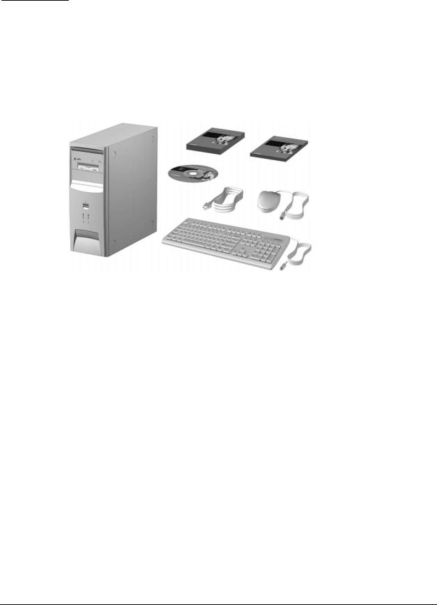
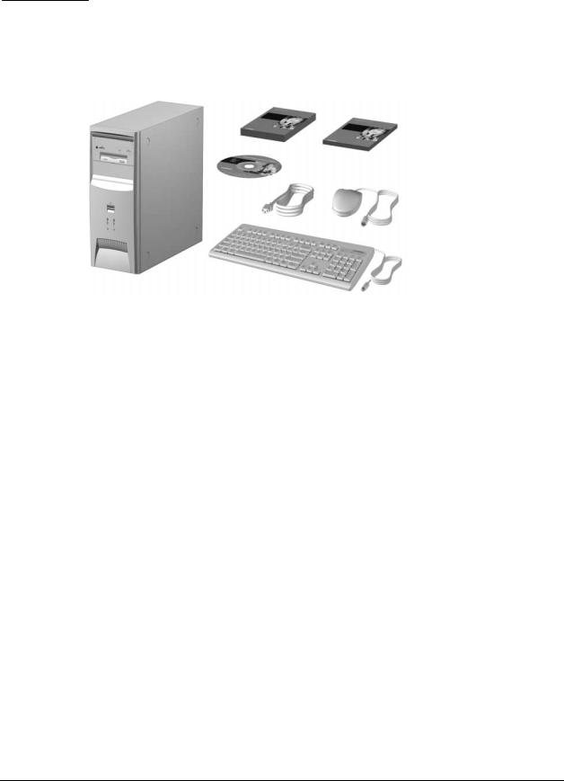
1.1Computer Features
Compaq Deskpro EX Series of Personal Computers Minitower Model ships with a mouse and keyboard. Some models are also equipped with a CD-ROM drive. A Compaq color monitor or other compatible monitor does not ship with the computer.
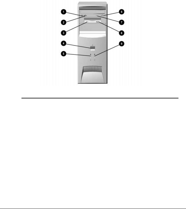
1.1.1Front Panel Controls and LEDs
Ref. |
Component/Function |
Ref. |
Component/Function |
1 |
Stereo Headphone Jack* |
6 |
CD-ROM Eject Button* |
|
|
|
|
2 |
Headphone Volume Control* |
7 |
CD-ROM Drive Busy Indicator* |
|
|
|
|
3 |
Diskette Drive Activity Light |
8 |
Diskette Eject Button |
|
|
|
|
4 |
Dual-State Power Button |
9 |
Drive Activity Light** |
|
|
|
|
5 |
Power-On Light |
|
|
|
|
|
|
*CD-ROM models only.
**Flashes when an ATAPI device, such as the hard drive, is active.
1-2 Product Description
1.1.2Rear Panel Connectors
Ref. |
Component |
Ref. |
Component |
1 |
Mouse Connector |
6 |
Monitor Connector |
|
|
|
|
2 |
Keyboard Connector |
7 |
Headphone/Line-Out Audio Connector |
|
|
|
|
3 |
Universal Serial Bus (USB) |
8 |
Serial Connector |
|
Connectors (2) (connects the |
|
|
|
computer to any USB peripheral |
|
|
|
while the computer is operating; is |
|
|
|
a fully functional plug and play |
|
|
|
connector) |
|
|
|
|
|
|
4 |
Serial Connector |
9 |
Line-In Audio Connector |
|
|
|
|
5 |
Parallel Port Connector |
: |
Microphone Connector |
|
|
|
|
Compaq Deskpro EX and Deskpro EXS Series of Personal Computers 1-3
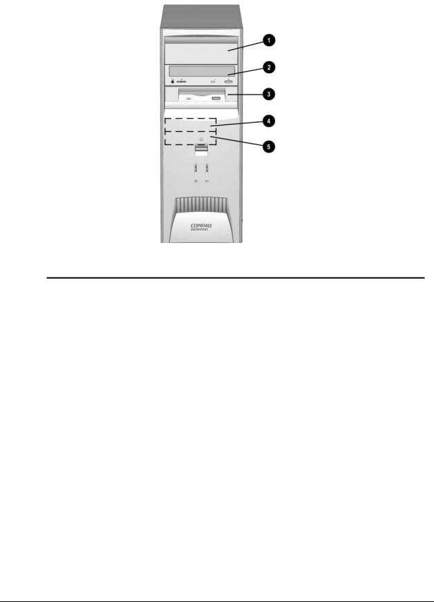
1.1.3Drive Positions
Reference Drive Bay |
Configuration |
|
1, 2 |
1, 2 |
Two standard 5.25-inch, half-height bays for optional drives |
|
|
|
3 |
3 |
One standard 3.5-inch, 1.44-MB diskette drive mounted with a drive |
|
|
adapter into a 5.25-inch bay |
|
|
|
4, 5 |
4, 5 |
Two standard 3.5-inch drive bays; Bay 4 contains the preinstalled hard |
|
|
drive; Bay 5 is available for an optional hard drive |
|
|
|
Drive bay numbers are stamped on the chassis.
To verify the type and size of the mass storage devices installed in the computer, run F10 Compaq Computer Setup.
1-4 Product Description
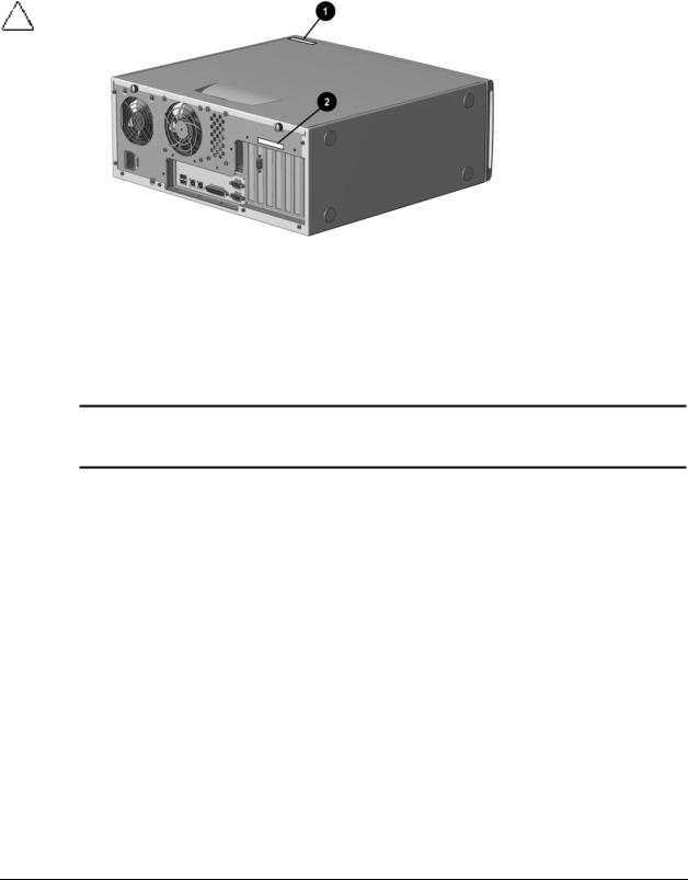
1.2Serial Number Location
The serial number and model information label is located on the access panel of the unit 1. A second barcode label is located on the rear of the unit 2.
For the purpose of AssetControl, the serial number is embedded in CMOS and in the EEPROM on the system board and may be accessed through Diagnostics for Windows.
If the system board is replaced with a spare part from Compaq, the invalid serial number condition will be recognized during POST. The original serial number must then be reentered through Computer Setup. Refer to the Software Reference Guide for more information.
CAUTION: A system board borrowed from another computer is recognized as a valid serial number and will create a mismatch between the serial number label and the electronic serial number.
The computer serial number should be provided to Compaq when requesting information or ordering spare parts.
Compaq Deskpro EX and Deskpro EXS Series of Personal Computers 1-5
chapter 2
SPARE PARTS
Compaq Deskpro EX and Deskpro EXS Series of Personal Computers 2-1
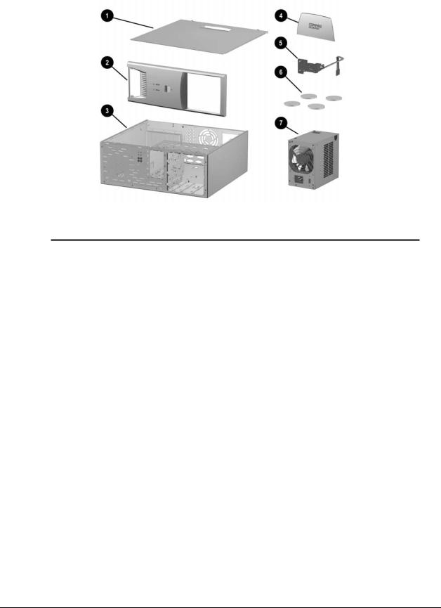
2.1System Unit
|
|
Spare Part |
Warranty |
Description |
Number |
Tier |
|
1 |
Access panel |
Not spared |
|
|
|
|
|
2 |
Front bezel |
166868-001 |
B |
|
|
|
|
3 |
Chassis/basepan |
Not spared |
|
|
|
|
|
4 |
Logo Kit (only minitower version-166806-002-used) |
166924-001 |
B |
|
|
|
|
5 |
Power switch with cable, LED and switch holder |
199854-001 |
|
|
|
|
|
6 |
Feet |
Misc Plastics Kit |
B |
|
|
|
|
7 |
Power supply |
201828-001 |
B |
|
|
|
|
2-2 Spare Parts
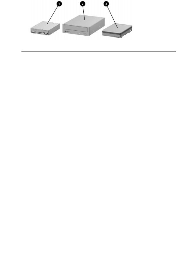
2.2Mass Storage Devices
|
|
Spare Part |
Warranty |
Description |
Number |
Tier |
|
1 |
Diskette drive, 3.5-inch |
158266-001 |
D |
|
|
|
|
2 |
48X Max tray load IDE CD-ROM drive |
187263-001 |
B |
|
|
|
|
3 |
10.0-GB Ultra ATA hard drive (66/5400) quiet |
203139-001 |
B |
|
|
|
|
* |
15.0-GB Ultra ATA hard drive (66/5400) |
202903-001 |
B |
|
|
|
|
*Not shown
(nn/nnnn) = hard drive transfer rate (MBytes/sec)/RPM
Ultra ATA/100 hard drives are backwards compatible with Ultra ATA/66 devices; however, the data transfer rate is reduced to 66MB/sec.
Compaq Deskpro EX and Deskpro EXS Series of Personal Computers 2-3

2.3Cables
|
Spare Part |
Warranty |
Description |
Number |
Tier |
Cable Kit includes: |
192264-001 |
B |
|
|
|
1Single device, hard drive/CD-ROM cable, 18” (108950-019)
2Audio cable, 21” (387527-001)
*Single device, hard drive/CD-ROM cable, 12.5” (105876-001)
*Audio cable, 21”, (288489-002) (not used for this product)
3Single device, hard drive/CD-ROM cable, 9.75” (108950-021)
4 |
Dual device, hard drive/CD-ROM cable, 18”, 10” to the first |
196667-001 |
B |
|
connector |
|
|
|
|
|
|
5 |
Power switch/LED cable |
199854-001 |
B |
|
|
|
|
6 |
Diskette drive cable |
161735-001 |
B |
|
|
|
|
* |
CD audio cable |
149806-001 |
D |
|
|
|
|
*Not shown
2-4 Spare Parts
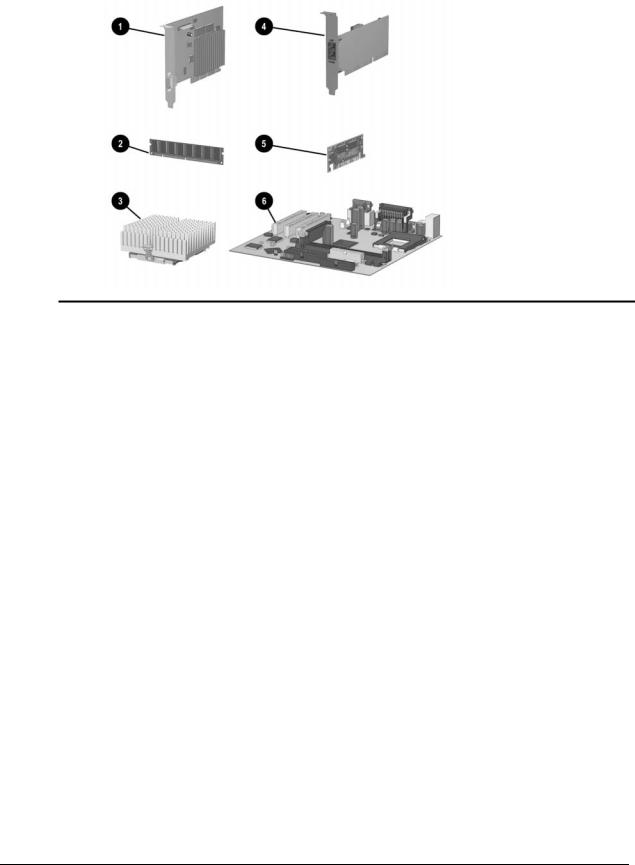
2.4Standard, Memory, and Expansion Boards
|
|
Spare Part |
Warranty |
Description |
Number |
Tier |
|
1 Nvidia M64 16MB SDRAM AGP Card |
182757-001 |
B |
|
|
|
|
|
5 AIMM (GPA) 4MB, 133MHz for graphics |
192012-001 |
B |
|
|
|
|
|
|
Memory Module (SDIMM, 133 MHz) |
|
|
|
|
|
|
2 |
128 MB |
170081-001 |
B |
|
|
|
|
|
256 MB |
192014-001 |
B |
|
|
|
|
|
Intel Pentium III Processor |
|
|
|
|
|
|
3 |
566/66 MHz with heatsink (191832-002) and clip (223575-007). |
203967-001 |
B |
|
|
|
|
* |
600/66 MHz with heatsink (191832-002) and clip (223575-007). |
192011-001 |
B |
|
|
|
|
* |
667/133 MHz with heatsink (191832-002) and clip (223575-007). |
192007-001 |
B |
|
|
|
|
* |
700/66 MHz with heatsink (191832-002) and clip (223575-007). |
203968-001 |
B |
|
|
|
|
* |
733/133 MHz with heatsink (191832-002) and clip (223575-007). |
192008-001 |
B |
|
|
|
|
* |
800/133 MHz with heatsink (191832-002) and clip (223575-007). |
192009-001 |
B |
|
|
|
|
* |
866/133 MHz with fansink (191845-002). Fansink includes fan, |
192006-001 |
B |
|
heatsink, and clip. |
|
|
|
|
|
|
* |
933/133 MHz with fansink (191845-002). Fansink includes fan, |
203969-001 |
B |
|
heatsink, and clip. |
|
|
|
|
|
|
4 10/100 PCI Network Interface Card |
188297-001 |
B |
|
|
|
|
|
6 |
System Board |
203966-001 |
B |
|
|
|
|
*Not shown. |
|
|
|
Compaq Deskpro EX and Deskpro EXS Series of Personal Computers 2-5

2.5Miscellaneous Plastics Kit
|
Spare Part |
Warranty |
Description |
Number |
Tier |
Miscellaneous Plastics Kit, includes: |
166878-001 |
B |
1Panel, sub (166835-001)
2Bezel, blank (166775-001)
3Diskette bezel (166776-001)
4Card guide (166778-001)
5Foot, rubber (4 ea.) (166939-002)
6Button, power (166774-001)
7Drivelock, DT (166779-001) (not used with this product)
8Spring, power button (166837-001)
9Springs, drivelock (2 ea.) (166837-002)
10 Drivelock, MT (166780-001)
* Retention mechanism (2 ea.) (350767-001)
*Not shown
2-6 Spare Parts

2.6Keyboards (not illustrated)
|
Spare Part |
Warranty |
Description |
Number |
Tier |
Easy Access Keyboard-US |
123130-xxx |
D |
|
|
|
Dutch |
-331 |
|
|
|
|
Finnish |
-351 |
|
|
|
|
French |
-051 |
|
|
|
|
International |
-B31 |
|
|
|
|
Norwegian |
-091 |
|
|
|
|
Spanish |
-071 |
|
|
|
|
Swedish |
-101 |
|
|
|
|
UK |
-031 |
|
|
|
|
US |
-001 |
|
|
|
|
2.7Miscellaneous Screw Kit (not illustrated)
|
Spare Part |
Warranty |
Description |
Number |
Tier |
Miscellaneous Screw Kit, includes: |
179180-001 |
D |
|
|
|
6-32 x 1/4 hi-top, thread-forming screw with serrations (5 ea.) (192308-001)
6-19 x 5/16 panhead, plastite screw (4 ea.) (101346-068)
6-19 x .5/16 hi-top, taptite screw with captive washer (4 ea.) (114399-069)
6-32 x 3/16 hi-top, thread-forming screw with serrations (5 ea.) (192308-003)
M3 x 5mm, hi-top, taptite screw with serrations (4 ea.) (247348-001)
6-32 x 3/16 buttonhead tamper-resistant, taptite screw with serrations (3 ea.) (296769-002)
6-32 x 5/16 hi-top, taptite screw (4 ea.) (109834-568)
6-19 x 1/2 Panhead, plastite screw (5 ea.) (101346-071)
Thumbscrew, molded cap (4 ea.) (179333-002)
Compaq Deskpro EX and Deskpro EXS Series of Personal Computers 2-7
2.8Miscellaneous Parts (not illustrated)
|
|
Spare Part |
Warranty |
|
Description |
Number |
Tier |
|
|
|
|
|
Mouse – Scroll, Opal |
334689-002 |
D |
|
|
|
|
2.9 |
Shipping Boxes (not illustrated) |
|
|
|
|
|
|
|
Description |
Spare Part Number |
|
|
Return Kit |
166990-002 |
|
|
|
|
|
2.10 |
Documentation and Software (not illustrated) |
|
|
|
|
|
|
|
Description |
Spare Part Number |
|
|
Maintenance & Service Guide |
215879-001 |
|
|
|
|
|
|
Illustrated Parts Map |
215880-001 |
|
|
|
|
|
|
Service Reference Guide |
152611-001 |
|
|
|
|
|
|
Quick Troubleshooting Guide |
153837-001 |
|
|
|
|
|
2-8 Spare Parts

chapter 3
REMOVAL & REPLACEMENT PRELIMINARIES
This chapter provides general service information for the computer. Adherence to the procedures and precautions described in this chapter is essential for proper service.
CAUTION: When the computer is plugged into an AC power source there is always voltage applied to the system board. You must disconnect the power cord from the power source before opening the computer to prevent system board or component damage.
3.1Electrostatic Discharge Information
A sudden discharge of static electricity from your finger or other conductor can destroy static-sensitive devices or microcircuitry. Often the spark is neither felt nor heard, but damage occurs. An electronic device exposed to electrostatic discharge (ESD) may not be affected at all and can work perfectly throughout a normal cycle. The device may function normally for a while, then degrade in the internal layers, reducing its life expectancy.
Networks built into many integrated circuits provide some protection, but in many cases, the discharge contains enough power to alter device parameters or melt silicon junctions.
3.1.1Generating Static
The following table shows that:
!Different activities generate different amounts of static electricity.
!Static electricity increases as humidity decreases.
|
Relative Humidity |
|
||||
Event |
55% |
40% |
10% |
|||
Walking across carpet |
7,500 |
V |
15,000 |
V |
35,000 |
V |
Walking across vinyl floor |
3,000 |
V |
5,000 |
V |
12,000 |
V |
Motions of bench worker |
400 |
V |
800 |
V |
6,000 |
V |
Removing DIPs* from plastic tube |
400 |
V |
700 |
V |
2,000 |
V |
Removing DIPs* from vinyl tray |
2,000 |
V |
4,000 |
V |
11,500 |
V |
Removing DIPs* from Styrofoam |
3,500 |
V |
5,000 |
V |
14,500 |
V |
Removing bubble pack from PCB |
7,000 |
V |
20,000 |
V |
26,500 |
V |
Packing PCBs in foam-lined box |
5,000 |
V |
11,000 |
V |
21,000 |
V |
*Dual Inline Packaging (DIP) is the packaging around individual microcircuitry. These are then multi-packaged inside plastic tubes, trays, or Styrofoam.
700 volts can degrade a product.
Compaq Deskpro EX and Deskpro EXS Series of Personal Computers 3-1

3.1.2Preventing Electrostatic Damage to Equipment
Many electronic components are sensitive to ESD. Circuitry design and structure determine the degree of sensitivity. The following proper packaging and grounding precautions are necessary to prevent damage to electric components and accessories.
!To avoid hand contact, transport products in static-safe containers such as tubes, bags, or boxes.
!Protect all electrostatic parts and assemblies with conductive or approved containers or packaging.
!Keep electrostatic sensitive parts in their containers until they arrive at static-free stations.
!Place items on a grounded surface before removing them from their container.
!Always be properly grounded when touching a sensitive component or assembly.
!Avoid contact with pins, leads, or circuitry.
!Place reusable electrostatic-sensitive parts from assemblies in protective packaging or conductive foam.
3.1.3Personal Grounding Methods and Equipment
Use the following equipment to prevent static electricity damage to equipment:
!Wrist straps are flexible straps with a minimum of one-megohm +/- 10% resistance in the ground cords. To provide proper ground, a strap must be worn snug against bare skin. The ground cord must be connected and fit snugly into the banana plug connector on the grounding mat or workstation.
!Heel straps/Toe straps/Boot straps can be used at standing workstations and are compatible with most types of shoes or boots. On conductive floors or dissipative floor mats, use them on both feet with a minimum of one-megohm +/- 10% resistance between the operator and ground.
Static Shielding Protection Levels
Method |
Voltage |
Antistatic plastic |
1,500 |
Carbon-loaded plastic |
7,500 |
Metallized laminate |
15,000 |
3.1.4Grounding Workstations
To prevent static damage at the workstation, use the following precautions:
!Cover the workstation with approved static-dissipative material. Provide a wrist strap connected to the work surface and properly grounded tools and equipment.
!Use static-dissipative mats, foot straps, or air ionizers to give added protection.
!Handle electrostatic sensitive components, parts, and assemblies by the case or PCB laminate. Handle them only at static-free workstations.
!Turn off power and input signals before inserting and removing connectors or test equipment.
3-2 Removal & Replacement Preliminaries

!Use fixtures made of static-safe materials when fixtures must directly contact dissipative surfaces.
!Keep work area free of nonconductive materials such as ordinary plastic assembly aids and Styrofoam.
!Use field service tools, such as cutters, screwdrivers, and vacuums, that are conductive.
3.1.5Recommended Materials and Equipment
Materials and equipment that are recommended for use in preventing static electricity include:
!Antistatic tape
!Antistatic smocks, aprons, or sleeve protectors
!Conductive bins and other assembly or soldering aids
!Conductive foam
!Conductive tabletop workstations with ground cord of one-megohm +/- 10% resistance
!Static-dissipative table or floor mats with hard tie to ground
!Field service kits
!Static awareness labels
!Wrist straps and footwear straps providing one-megohm +/- 10% resistance
!Material handling packages
!Conductive plastic bags
!Conductive plastic tubes
!Conductive tote boxes
!Opaque shielding bags
!Transparent metallized shielding bags
!Transparent shielding tubes
3.2Routine Care
3.2.1General Cleaning Safety Precautions
1.Never use solvents or flammable solutions to clean the computer.
2.Never immerse any parts in water or cleaning solutions; apply any liquids to a clean cloth and then use the cloth on the component.
3.Always turn off the computer when cleaning with liquids or damp cloths.
4.Always turn off the computer before cleaning the keyboard, mouse, or air vents.
5.Disconnect the keyboard before cleaning it.
6.Wear safety glasses equipped with side shields when cleaning the keyboard.
Compaq Deskpro EX and Deskpro EXS Series of Personal Computers 3-3
 Loading...