


. . . . . . . . . . . . . . . . . . . . . . . . . . . . . . . . . . . . .
Notice
The information in this guide is subject to change without notice.
COMPAQ COMPUTER CORPORATION SHALL NOT BE LIABLE FOR TECHNICAL OR EDITORIAL ERRORS OR OMISSIONS CONTAINED HEREIN; NOR FOR INCIDENTAL OR CONSEQUENTIAL DAMAGES RESULTING FROM THE FURNISHING, PERFORMANCE, OR USE OF THIS MATERIAL.
This guide contains information protected by copyright. No part of this guide may be photocopied or reproduced in any form without prior written consent from Compaq Computer Corporation.
© 1998 Compaq Computer Corporation. All rights reserved. Printed in the U.S.A.
Compaq and LTE are registered is the U. S. Patent and Trademark Office.
Armada is a trademark of Compaq Computer Corporation.
Microsoft, MS-DOS, and Windows are registered trademarks of Microsoft Corporation.
The software described in this guide is furnished under a license agreement or nondisclosure agreement. The software may be used or copied only in accordance with the terms of the agreement.
Product names mentioned herein may be trademarks and/or registered trademarks of their respective companies.
Maintenance and Service Guide
Compaq Armada 4100 and 4200 Families of Personal Computers
First Edition (January 1998)
Documentation Part Number 234843-002
Spare Part Number 273027-002
Compaq Computer Corporation

. . . . . . . . . . . . . . . . . . . . . . . . . . . . . . . . . . . . .
Contents
Preface.......................................................................................................................... |
xi |
Symbols ........................................................................................................ |
xi |
Technician Notes .......................................................................................... |
xi |
Laser Safety ................................................................................................ |
xii |
CDRH Regulations..................................................................................... |
xii |
Locating Additional Information............................................................... |
xiii |
Chapter 1 |
|
Product Description |
|
1.1 Computer Features and Models........................................................... |
1-1 |
1.2 Models ................................................................................................. |
1-2 |
1.3 Standard Features ................................................................................ |
1-3 |
1.3.1 Software Fulfillment .................................................................... |
1-5 |
1.3.2 Security Features.......................................................................... |
1-5 |
1.3.3 Power Management...................................................................... |
1-5 |
1.4 Options ................................................................................................ |
1-6 |
1.4.1 System Memory Options ............................................................. |
1-6 |
1.4.2 Display Options ........................................................................... |
1-7 |
1.4.3 Secondary Cache.......................................................................... |
1-7 |
1.4.4 Mobile CD Expansion Unit.......................................................... |
1-7 |
1.4.5 Convenience Base ........................................................................ |
1-7 |
1.4.6 Mass Storage Options .................................................................. |
1-7 |
1.4.7 AC Adapter .................................................................................. |
1-8 |
1.4.8 Automobile Adapter..................................................................... |
1-8 |
1.4.9 Lithium Ion Battery Pack ............................................................. |
1-8 |
1.4.10 External Battery Charger ........................................................... |
1-8 |
1.4.11 External Keyboards.................................................................... |
1-8 |
1.4.12 External Monitors ...................................................................... |
1-8 |
1.4.13 Compaq Mouse .......................................................................... |
1-9 |
1.4.14 Trackball Pointing Device ......................................................... |
1-9 |
1.5 External Computer Components ......................................................... |
1-9 |
1.5.1 Front and Left Side Components ................................................. |
1-9 |
1.5.2 Front and Right Side Components ............................................. |
1-11 |
1.5.3 Rear Components....................................................................... |
1-12 |
1.5.4 Bottom Components .................................................................. |
1-13 |
1.5.5 Status Panel Lights..................................................................... |
1-14 |
1.6 Mobile CD Expansion Unit Components......................................... |
1-15 |
1.7 Convenience Base Connectors .......................................................... |
1-17 |
1.8 Design Overview - Computer............................................................ |
1-18 |
1.8.1 System Unit................................................................................ |
1-18 |
1.8.2 System Board ............................................................................. |
1-18 |
1.8.3 Processor Board ......................................................................... |
1-19 |
1.8.4 Processor .................................................................................... |
1-19 |
Contents v

. . . . . . . . . . . . . . . . . . . . . . . . . . . . . . . . . . . . .
1.8.5 System Memory.......................................................................... |
1-19 |
|
1.8.6 Cache .......................................................................................... |
1-19 |
|
1.8.7 Local Bus Video ......................................................................... |
1-20 |
|
Chapter 2 |
|
|
2.1 |
Preliminary Steps ................................................................................ |
2-2 |
2.2 |
Clearing the Power-On and Setup Passwords ..................................... |
2-3 |
2.3 |
Power-On Self Test (POST)................................................................ |
2-4 |
2.4 |
POST Error Messages ......................................................................... |
2-4 |
2.5 |
Compaq Utilities ................................................................................. |
2-7 |
2.5.1 Running Computer Setup ............................................................ |
2-7 |
|
2.5.2 Running Computer Checkup (TEST) .......................................... |
2-8 |
|
2.5.3 View System Information (INSPECT) ...................................... |
2-10 |
|
2.6 |
Diagnostic Error Codes ..................................................................... |
2-11 |
2.7 |
Troubleshooting Without Diagnostics .............................................. |
2-17 |
2.7.1 Solving Minor Problems............................................................ |
2-17 |
|
Chapter 3 |
|
|
Illustrated Parts |
|
|
3.1 |
System Unit.......................................................................................... |
3-2 |
3.2 |
Mass Storage Devices .......................................................................... |
3-6 |
3.3 |
Cables and Power Cords ...................................................................... |
3-8 |
3.4 |
Standard and Optional Boards ........................................................... |
3-10 |
3.5 |
Display Assembly .............................................................................. |
3-12 |
3.6 |
Options ............................................................................................... |
3-14 |
3.8 |
Miscellaneous Parts............................................................................ |
3-16 |
3.8 |
Shipping Boxes .................................................................................. |
3-18 |
3.9 |
Documentation ................................................................................... |
3-19 |
Chapter 4 |
|
|
Removal and Replacement Preliminaries |
|
|
4.1 |
Electrostatic Discharge ........................................................................ |
4-1 |
4.1.1 Generating Static .......................................................................... |
4-1 |
|
4.1.2 Preventing Electrostatic Damage to Equipment ........................... |
4-2 |
|
4.1.3 Removing Batteries ...................................................................... |
4-2 |
|
4.1.4 Preventing Damage to Drives ....................................................... |
4-3 |
|
4.1.5 Grounding Methods ...................................................................... |
4-3 |
|
4.1.6 Grounding Workstations............................................................... |
4-4 |
|
4.1.7 Grounding Equipment .................................................................. |
4-4 |
|
4.1.8 Recommended Materials and Equipment ..................................... |
4-5 |
|
4.2 |
Service Considerations......................................................................... |
4-6 |
4.2.1 Tool Requirements........................................................................ |
4-6 |
|
4.2.2 Cables and Connectors ................................................................. |
4-6 |
|
4.3 |
Serial Number ...................................................................................... |
4-6 |
vi Contents

. . . . . . . . . . . . . . . . . . . . . . . . . . . . . . . . . . . . .
Chapter 5
Removal and Replacement Procedures
5.1 |
Serial Number...................................................................................... |
5-1 |
5.2 |
Disassembly Sequence Chart .............................................................. |
5-2 |
5.3 |
Preparing the Computer for Disassembly............................................ |
5-3 |
5.3.1 Disconnecting the AC Power and |
|
|
External Diskette Drive Bay ................................................................. |
5-4 |
|
5.3.2 Undocking the Computer ............................................................. |
5-5 |
|
5.3.3 Battery Packs.............................................................................. |
5-11 |
|
5.3.4 DualBay Battery Pack and Devices .......................................... |
5-13 |
|
5.3.4 Pointing Devices ........................................................................ |
5-16 |
|
5.3.5 Hard Drive.................................................................................. |
5-18 |
|
5.3.6 PC Card ...................................................................................... |
5-19 |
|
5.4 |
External Computer Components ....................................................... |
5-20 |
5.4.1 Computer Logo .......................................................................... |
5-20 |
|
5.4.2 Computer Feet............................................................................ |
5-21 |
|
5.4.3 Handle ........................................................................................ |
5-22 |
|
5.5 |
CPU Base Assembly ......................................................................... |
5-26 |
5.5.1 Memory Cover ........................................................................... |
5-27 |
|
5.5.2 Memory Boards.......................................................................... |
5-28 |
|
5.5.3 Lithium Real Time Clock Battery.............................................. |
5-30 |
|
5.5.4 CPU Base Cover ........................................................................ |
5-31 |
|
5.5.5 Processor Shield and Board ...................................................... |
5-34 |
|
5.5.6 CPU Cover and Keyboard Assembly........................................ |
5-36 |
|
5.6 |
Display Assembly.............................................................................. |
5-40 |
5.7 |
Clutch Assembly Components .......................................................... |
5-44 |
5.7.1 Clutch Cover .............................................................................. |
5-44 |
|
5.7.2 Clutches...................................................................................... |
5-46 |
|
5.8 |
System Board Components ............................................................... |
5-47 |
5.8.1 System Board ............................................................................. |
5-47 |
|
5.8.2 Ensuring ESD Protection ........................................................... |
5-52 |
|
5.8.3 Heatsink and Video Chip Heatpipe........................................... |
5-53 |
|
5.9 |
Frame Components............................................................................ |
5-56 |
5.9.1 Upper PCMCIA Door ................................................................ |
5-56 |
|
5.9.2 Lower PCMCIA Door................................................................ |
5-59 |
|
5.9.3 DualBay Eject Assembly ........................................................... |
5-62 |
|
5.9.5 PCMCIA Assembly .................................................................. |
5-64 |
|
5.9.6 PCMCIA Ejector Buttons .......................................................... |
5-67 |
|
5.9.7 Display Ground Bracket............................................................. |
5-69 |
|
Chapter 6
Specifications
6.1 |
Computer ............................................................................................. |
6-2 |
6.2 |
Displays .............................................................................................. |
6-3 |
6.3 |
Hard Drives ......................................................................................... |
6-6 |
Contents vii

. . . . . . . . . . . . . . . . . . . . . . . . . . . . . . . . . . . . .
6.4 |
Diskette Drive ...................................................................................... |
6-9 |
|
6.5 |
|
CD-ROM Drives ............................................................................... |
6-10 |
6.6 |
|
Battery Packs..................................................................................... |
6-13 |
6.7 |
Mobile CD Expansion Unit................................................................ |
6-14 |
|
6.8 |
External Power Supplies .................................................................... |
6-15 |
|
6.9 |
System Interrupts ............................................................................... |
6-18 |
|
6.10 System DMA.................................................................................... |
6-19 |
||
6.11 |
System I/O Address ........................................................................ |
6-20 |
|
6.12 |
System Memory Map...................................................................... |
6-22 |
|
Appendix A |
|
Connector Pin Assignments ................................................................................... |
A-1 |
Appendix B |
|
Power Cord Set Requirements .............................................................................. |
B-1 |
3-Conductor Power Cord Set .................................................................... |
B-1 |
General Requirements .......................................................................... |
B-1 |
Country-Specific Requirements............................................................ |
B-2 |
Index................................................................................................................................... |
I-1 |
viii Contents

. . . . . . . . . . . . . . . . . . . . . . . . . . . . . . . . . . . . .
Preface
Preface
This Maintenance and Service Guide is a troubleshooting guide that can be used for reference when servicing the Compaq Armada 4100 and 4200 Families of Personal Computers. Additional information is available in the Service Quick Reference Guide and in QuickFind.
Compaq Computer Corporation reserves the right to make changes to the Compaq Armada 4100 and 4200 Families of Personal Computers without notice.
Symbols
The following symbols and words mark special messages throughout this guide:
! |
WARNING: Text set off in this manner indicates that failure to follow directions in the |
warning could result in bodily harm or loss of life. |
|
|
|
|
CAUTION: Text set off in this manner indicates that failure to follow directions could |
|
result in damage to equipment or loss of data. |
|
|
IMPORTANT: Text set off in this manner presents clarifying information or specific instructions.
NOTE: Text set off in this manner presents commentary, sidelights, or other points of information.
Technician Notes
! |
WARNING: Only authorized technicians trained by Compaq should attempt to repair |
this equipment. All troubleshooting and repair procedures are detailed to allow only |
|
|
subassembly/module level repair. Because of the complexity of the individual boards and |
|
subassemblies, no one should attempt to make repairs at the component level or to |
|
make modifications to any printed wiring board. Improper repairs can create a safety |
|
hazard. Any indication of component replacement or printed wiring board modifications |
|
may void any warranty or exchange allowances. |
|
|
|
CAUTION: To properly ventilate your system, you must provide at least 3 inches |
|
(7.62 cm) of clearance on the front and back of the computer. |
|
|
! |
WARNING: The computer is designed to be electrically grounded. To ensure proper |
operation, plug the AC power cord into a properly grounded electrical outlet only. |
|
|
|
Preface xi
. . . . . . . . . . . . . . . . . . . . . . . . . . . . . . . . . . . . . .
Laser Safety
All Compaq systems, equipped with CD-ROM drives, comply with appropriate safety standard including IEC 825. With specific regard to the laser, the equipment complies with laser product performance standards set by government agencies as a Class 1 laser product. It does not emit hazardous light; the beam is totally enclosed during all modes of customer operation and maintenance.
CDRH Regulations
The Center for Devices and Radiological Health (CDRH) of the U.S. Food and Drug Administration implemented regulations for laser products on August 2, 1976. These regulations apply to laser products manufactured from August 1, 1976. Compliance is mandatory for products marketed in the United States.
WARNING: Use of controls or adjustments or performance of procedures ! other than those specified herein or in the CD ROM installation guide may
result in hazardous radiation exposure.
This system is classified as a CLASS 1 LASER PRODUCT. This label is located on the outside of your system. A similar label also appears on the internal CD-ROM installed in your system.
LASER INFO |
|
Laser Type: |
Semiconductor GaAIAs |
Wave Length: |
780 +/- 35 nm |
Divergence Angle: |
53.5 Degree +/- 1.5 Degree |
Output Power: |
Less than 0.2mW or 10,869 W∙m-2sr-1 |
Polarization: |
Circular |
Numerical Aperture: |
0.45 +/- 0.04 |
Only authorized technicians trained by Compaq should attempt to repair this equipment. All troubleshooting and repair procedures are detailed to allow only subassembly/module level repair. Because of the complexity of the individual boards and subassemblies, no one should attempt to make repairs at the component level or to make modifications to any printed wiring board. Improper repairs can create a safety hazard.
xii Preface

. . . . . . . . . . . . . . . . . . . . . . . . . . . . . . . . . . . . . .
Locating Additional Information
The following documentation is available to support the products:
■Quick Setup
■Reference Guide
■Introducing Microsoft Windows 95
■Compaq Service Quick Reference Guide
■Service Training Guides
■Compaq Service Advisories and Bulletins
■Compaq QuickFind
■Technical Reference Guide
Preface xiii

. . . . . . . . . . . . . . . . . . . . . . . . . . . . . . . . . . . . .
Chapter 1
Product Description
1.1Computer Features and Models
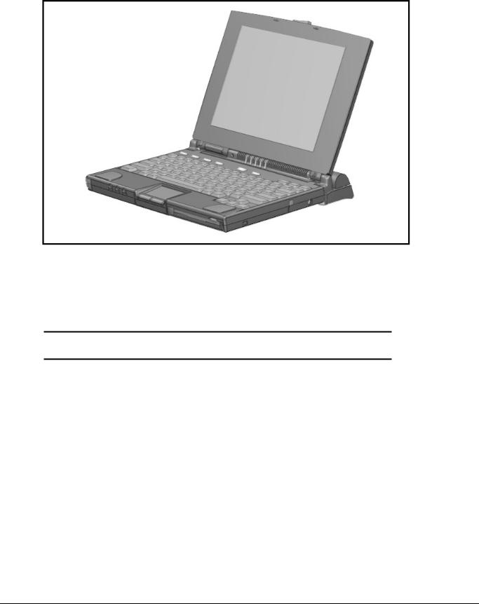
The Compaq Armada 4100 and 4200 Families are mobile notebook computers with advanced modularity, processors, and video graphics. Both families provide fullfunction, Pentium-based notebook computers that allow desktop functionality and connectivity through the use of an optional Mobile CD (MCD) Expansion Unit and a convenience base.
The 4100 Family provides light weight multimedia models with up to 166-MHz processors with MMx technology, 8- or 16-MB of system memory, hard drive capacity up to 2.0 GB, and primary battery power from the handle battery.
The 4200 Family provides slimline models with 233or 266-MHz processor, 32-MB of system memory, hard drive capacity up to 4-GB, and primary battery power from the modular battery pack in the DualBay.
This chapter describes the features of these computer models.
■
■
■
■
■
■
■
■
■
■
■
■
■
Compaq Armada 4100
Compaq Armada 4110 and 4110D
Compaq Armada 4115
Compaq Armada 4120 and 4120T
Compaq Armada 4125D and 4125T
Compaq Armada 4130T
Compaq Armada 4131T
Compaq Armada 4140T
Compaq Armada 4150 and 4150T
Compaq Armada 4160T
Compaq Armada 4160T Slimline
Compaq Armada 4210T
Compaq Armada 4220T
Product Description |
1-1 |
. . . . . . . . . . . . . . . . . . . . . . . . . . . . . . . . . . . . .
Figure 1-1. Compaq Armada 4100 and 4200
1.2Models
The following 4200 models are available:
Table 1-1
4200 Family of Personal Computers
|
|
|
|
|
Memory/ |
Model |
Processor |
Display |
Hard Drive |
Cache |
Upgrade |
|
|
|
|
|
|
4210T |
233-MHz Pentium |
12.1-inch CTFT |
3.0-GB |
256-KB (L2) |
32/96 |
4220T |
266-MHz Pentium |
12.1-inch CTFT |
4.0-GB |
512-KB (L2) |
32/96 |
|
|
|
|
|
|
1-2 Product Description
. . . . . . . . . . . . . . . . . . . . . . . . . . . . . . . . . . . . .
The following 4100 Family models are available:
Table 1-2
Compaq Armada 4100 Family of Personal Computers
|
|
|
|
|
Memory/ |
Model |
Processor |
Display |
Hard Drive |
Cache |
Upgrade |
|
|
|
|
|
|
4120 |
120-MHz Pentium |
11.3-inch CSTN |
810-MB |
256-KB |
16/48* |
4125D |
120-MHz Pentium |
11.3-inch CSTN |
810-MB |
256-KB |
8/40 |
4120T |
120-MHz Pentium |
11.8-inch CTFT |
810-MB |
256-KB |
8/40 |
4120T |
120-MHz Pentium |
11.8-inch CTFT |
810-MB |
256-KB |
16/48* |
4125T |
120-MHz Pentium |
11.8-inch CTFT |
810-MB |
256-KB |
16/48* |
4130T |
133-MHz Pentium |
11.8-inch CTFT |
1.08-GB |
256-KB |
16/48 |
4131T |
133-MHz Pentium |
11.8-inch CTFT |
1.4-GB |
256-KB |
16/48 |
4150 |
150-MHz Pentium w/ MMx |
12.1-inch CSTN |
1.6-GB |
256-KB |
16/80 |
4150T |
150-MHz Pentium w/ MMx |
12.1-inch CTFT |
1.6-GB |
256-KB |
16/80 |
4160T |
166-MHz Pentium w/ MMx |
12.1-inch CTFT |
2.0-GB |
256-KB |
16/80 |
4160T Slimline |
166-MHz Pentium w/ MMx |
12.1-inch CTFT |
2.0-GB |
256-KB |
16/80 |
|
|
|
|
|
|
* Japan only |
|
|
|
|
|
|
|
|
|
|
|
1.3Standard Features
Depending upon your computer model, the processor, DRAM, hard drive space, and color monitor type and size may vary:
Available in the Compaq Armada 4200 models:
■233or 266-MHz Pentium processors, upgradable to future Pentium technology
■64-bit graphics controller
■32-MB of dynamic random access memory (DRAM), expandable to 96 MB
■3-GB or 4-GB 2.5- inch hard drives (4-GB hard drive is not compatible with the 4100 modeles)
■12.1-inch Color Thin Film Transistor (CTFT) SVGA displays
■External Diskette Drive Bay
■Modular Lithium Ion (Li-ion) battery in the DualBay as the primary battery power
■32-bit cardbus PC card slot
■Handle battery in handle shell
Available in the Compaq Armada 4131T-4160T models:
■4131T has a 133-MHz Pentium procesor and the 4150 has a 150-MHz Pentium processor.The 4150 and the 4150T have 150-MHz Pentium processors with MMx technology. The 4160T and the 4160T slimline have 166-MHz Pentium processors with MMx technology.
■Cirrus logic LCD graphic controller
Product Description 1-3

. . . . . . . . . . . . . . . . . . . . . . . . . . . . . . . . . . . . .
■16-MB of dynamic random access memory (DRAM), expandable to 40-, 48or 80 MB
■1.4-GB, 1.6-GB, and 2-GB hard drives
■Lithium Ion (Li-ion) handle battery pack primary battery power
■16-bit PC card system
Available in the Compaq Armada 4100-4130T models:
■All models prior to and including the 4131T can be upgraded to a 133-MHz Pentium processor by replacing the processor board.
■75-, 100-, 120-, or 133-MHz Pentium processors.
■8- or 16-MB of dynamic random access memory (DRAM), expandable to 72or 80MB
■630-MB, 810-MB, or 1.08-GB 2.5- inch hard drives
■10.4-inch Color Super Twist Nematic (CSTN), 11.3-inch CSTN, or 11.8-inch Color Thin Film Transistor (CTFT) SVGA displays
■Lithium Ion (Li-ion) handle battery pack primary battery power
The following features are standard in both the Compaq Armada 4100 and 4200 Families:
■NTSC/PAL TV video allows full screen, full motion digital video presentation with interleaved synchronized stereo sound. MPEG accommodates full motion video in the range of 24 frames per second (cinema quality) to 30 frames per second (television quality).
■IDE hard drive in the dedicated hard drive bay. Cable select technology is employed for device 0/device 1 selection. The hard drive is secured in place with a pair of screws
■3.5-inch 1.44-MB diskette drive DualBay module supports a single diskette drive
■Supports Lithium Ion (Li-ion) and Nickel Metal Hydride (NiMH) handle battery packs
■Sound Blaster−compatible audio controller with internal stereo speakers and internal microphone
■Full-size 101 key compatible keyboard including 12 function keys, 8 cursor control keys, inverted-T cursor control keys, and embedded numeric keypad
■Four user-programmable keys
■Touchpad pointing device
■Operates from an internal battery pack or an AC adapter that is compatible with domestic or international power sources
■Power management and security features
1-4 Product Description

. . . . . . . . . . . . . . . . . . . . . . . . . . . . . . . . . . . . .
■Infrared interface for wireless communication with other IrDA-compliant devices at data rates up to 115 kbaud or 4 mbps on the 4210T, 4220T, 4150, 4150T, 4160T, and the 4160T Slimline models.
■Two PCMCIA standard device slots that will accommodate two types I and II and one type III PC Cards
■120-pin expansion connector provides the interface to the Mobile CD Expansion Unit (MCD) and the convenience base
■Rear-panel ports provide connections for parallel and serial, video out, keyboard/mouse, and IrDA compliant infrared devices
1.3.1Software Fulfillment
Backup software may be ordered directly from Compaq Computer Corporation through the Compaq Order Center. Both the model and serial numbers of the computer are needed to identify the specific software available.
For technical questions about software for the computer, contact a Compaq Technical Support Engineer. The model and serial numbers of the computer should be available before making the call.
1.3.2Security Features
The computer has the following security features:
■Ability to secure the computer and MCD Expansion Unit to an immovable object with an optional cable lock.
■Ability to establish power-on and setup passwords and to disable ports and devices from the Security menu in Computer Setup.
1.3.3Power Management
The computer supports three power management modes:
■Local Standby: The ability of individual subsystems to enter reduced power modes after predetermined periods of inactivity.
■Global Standby: The ability to place all subsystems in a reduced power mode after a predetermined period of inactivity.
■Hibernation: The ability to save the system configuration and user data to the hard disk, for restoration at a later time.
■ACPI Hardware Ready (Advanced Configuration and Power Interface): the 4200 Family models support the operation of hardware and software power specifications to interface in a single system and be used as needed.
In addition, there are the OFF and ON states. In the OFF state, the computer appears to be consuming no power; however, as long as there is a battery capable of supplying current, some components will be powered up, performing housekeeping tasks and
Product Description 1-5

. . . . . . . . . . . . . . . . . . . . . . . . . . . . . . . . . . . . .
waiting to be awakened. In the ON state, all systems are powered up and the unit is completely functional.
1.4Options
The 4100 and 4200 Families support the following options:
■MCD Expansion Unit
■Convenience base (Passthrough and Ethernet models)
■Memory expansion boards
■Li-ion handle battery packs
■Li-ion modular battery pack
■Automobile Adapter
■AC Adapter
■External Battery Charger
■PCMCIA modem
■Trackball pointing device
■AC power cords for international travelers
■Display upgrades (4100 Family models only)
■Hard drive upgrades (model dependent)
■Processor upgrades (4100 Family models only)
■External Battery Charger
■External keyboards
■External diskette drive bay
■Compaq mouse
■USB Cardbus PC card(4200 Family models only)
1.4.1System Memory Options
The computer supports optional 4-, 8-, 16-, 32-MB or 64-MB memory board sets. The memory boards are 70 ns Fast Page Mode DRAM SODIMMs, without parity. System memory can be expanded to 40, 48, or 96-MB of DRAM depending on the model.
The 4210T and 4220T models can support standard EDO and FP memory upgrades. Compaq does not offer EDO memory upgrade kits.
The system includes two DIMM slots that must be populated in pairs with DIMMs of equal size and type. Either parity or non-parity DIMMs may be used, but parity checking will not be enabled by the memory controller.
1-6 Product Description

. . . . . . . . . . . . . . . . . . . . . . . . . . . . . . . . . . . . .
1.4.2Display Options
The 4100 Family models with 11.3-inch, 11.8-inch, or CSTN displays can be upgraded to an 12.1-inch Color Thin Film Transistor (CTFT) SVGA display.
1.4.3Secondary Cache
The 4200 Family models are equipped with 256-KB or 512-KB secondary (L2) cache of write-back/write-through cache on the system I/O board.
Models 4110 through 4160T of the 4100 Family are equipped with 256-KB of write- back/write-through cache on the system I/O board.
1.4.4Mobile CD Expansion Unit
The Mobile CD-ROM Expansion Unit provides the following multimedia capabilities:
■CD-ROM drive
■Integrated stereo speakers
■Game port with MIDI support
■Dedicated battery bay
The CD-ROM drive is available in the optional MCD Expansion unit. The drive supports the following formats:
■ISO-9660, the most common CD-ROM format
■CD-ROM XA eXtended Architecture, a standard for storing multimedia information
■Photo CD (Kodak's format for storing photographic images on CD-ROM)
1.4.5Convenience Base
The convenience base provides the following added capabilities:
■Pass-through ports (serial, parallel, and video)
■Expansion features (mouse and keyboard ports, network support)
■Five-degree tilt for the notebook keyboard
■Charging of batteries in the system
■Integrated Ethernet (available on models with Ethernet capability)
1.4.6Mass Storage Options
A 4-GB hard drive is available as options for the 4210T. The 3-GB hard drive supports both the 4100 and 4200 Family models. Only a single diskette drive may be used at any one time with the computer. This drive may be used in the DualBay or externally with an optional parallel cable.
Product Description 1-7

. . . . . . . . . . . . . . . . . . . . . . . . . . . . . . . . . . . . .
1.4.7AC Adapter
The AC adapter supplies DC voltage to the system converter to operate and/or charge the installed battery pack(s). The adapter provides sufficient power to charge each main battery pack in 1.5 hours or less with the system off, or in 2.5 hours or less with the system on. The AC adapter power specifications are presented in Chapter 6.
1.4.8Automobile Adapter
The automobile adapter is used to charge the computer while traveling in an automobile. The Automobile Adapter power specifications are presented in Chapter 6.
1.4.9Lithium Ion Battery Pack
Lithium Ion (Li-ion) battery packs offer superior performance over nickel metal hydride batteries. NiMH batteries are not recommended. Li-ion batteries weigh approximately half as much as the NiMH battery packs and are compatible with the External Battery Charger and its charging options. They are available in both battery handle and modular bay forms.
1.4.10 External Battery Charger
The External Battery charger has the following features:
■Two battery charge slots
■Accepts Li-ion handle and modular batteries
■Fast charges one battery in 1.5 hours
■Fast charges two batteries in 3 hours
1.4.11 External Keyboards
The following external full-size keyboards are supported:
■Enhanced III keyboard
■SpaceSaver keyboard
■Alternative design keyboard
1.4.12 External Monitors
The following external monitors are supported:
■QVision 172 Color Monitor
■151 FS Color Monitor
■171 FS Color Monitor
■V50 Color
■V70 Color
1-8 Product Description

. . . . . . . . . . . . . . . . . . . . . . . . . . . . . . . . . . . . .
■P50 Color
■P70 Color
■P110 Color
■P1610 Color
■TFT500 Flat Panel
1.4.13 Compaq Mouse
The computer supports a PS/2 mouse or other external pointing device.
1.4.14 Trackball Pointing Device
The modular trackball provides an effective alternate to the touchpad or an external mouse when the machine is used in either a portable or desktop environment.
Product Description 1-9
. . . . . . . . . . . . . . . . . . . . . . . . . . . . . . . . . . . . .
1.5External Computer Components
The external computer components are illustrated and described in this section.
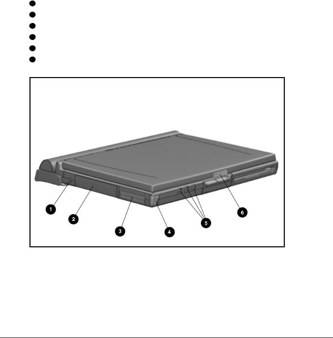
1.5.1Front and Left Side Components
The front and left side external components are shown in the following figure and identified in this section:
1Cable lock provision
2Hard drive compartment
3PC Card slots
4PC Card eject buttons
5Audio connectors
6Display latch
Figure 1-2. Front and Left Side Components
1-10 Product Description

. . . . . . . . . . . . . . . . . . . . . . . . . . . . . . . . . . . . .
1.5.2Front and Right Side Components
The front and right side computer components are shown and identified in this section.
1Pointing device
2DualBay module
3Speaker
4DualBay eject button
5AC power connector
6User programmable keys
Figure 1-3. Front and Right Side Components
Product Description 1-11
. . . . . . . . . . . . . . . . . . . . . . . . . . . . . . . . . . . . .
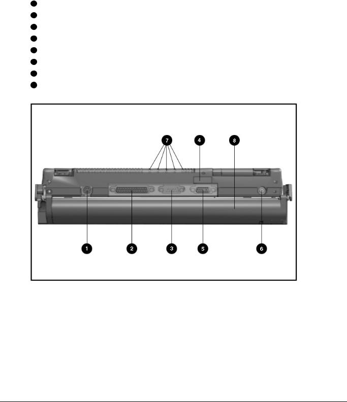
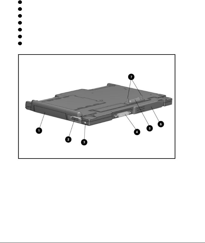
1.5.3Rear Components
The front and right side computer components are shown and identified in this section.
1Keyboard/mouse connector
2Parallel connector
3Serial connector
4Infrared lens (IrDA compliant)
5External monitor connector
6NTSC/PAL video
7Status panel indicator lights
8Handle
Figure 1-4. Rear Components
1-12 Product Description
. . . . . . . . . . . . . . . . . . . . . . . . . . . . . . . . . . . . .
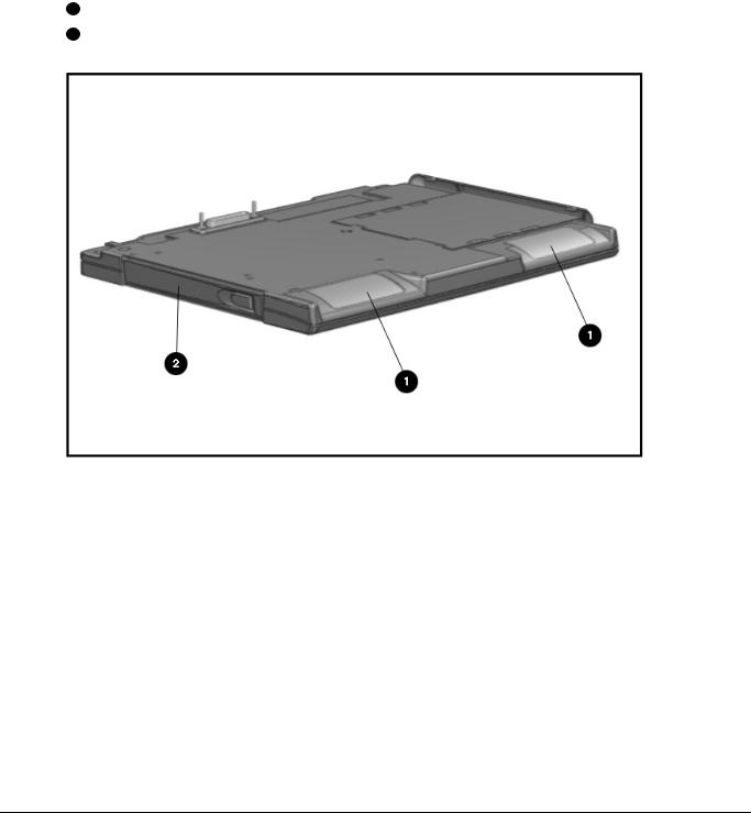
1.5.4Bottom Components
The bottom external components are shown in the following figure and are identified in this section:
1DualBay
2Pointing device
3Memory compartment
4Expansion slot
5Hard drive compartment
Figure 1-5. Bottom Components
Product Description 1-13

. . . . . . . . . . . . . . . . . . . . . . . . . . . . . . . . . . . . .
1.5.5Status Panel Lights
The status panel lights are shown in the following figure and are identified in this section:
1Power/Suspend
2Battery charge
3Caps Lock
4Scroll Lock
5Num Lock
Figure 1-6. Status Panel Lights
1-14 Product Description
. . . . . . . . . . . . . . . . . . . . . . . . . . . . . . . . . . . . .
1.6 Mobile CD Expansion
Unit Components
The front and left components of the Mobile CD Expansion Unit are shown in the following figure and are identified in this section:
1Stereo speakers
2CD-ROM drive
Figure 1-7. Left and Front Components
Product Description 1-15
. . . . . . . . . . . . . . . . . . . . . . . . . . . . . . . . . . . . .
The right and rear components are shown in the following figure and are identified in this section:
1Battery bay
2MIDI/game device
3AC adapter connector
4Convenience Base expansion connector
5Computer expansion connector
6Unlocking lever
7Expansion posts
Figure 1-8. Right and Rear Components
1-16 Product Description
. . . . . . . . . . . . . . . . . . . . . . . . . . . . . . . . . . . . .
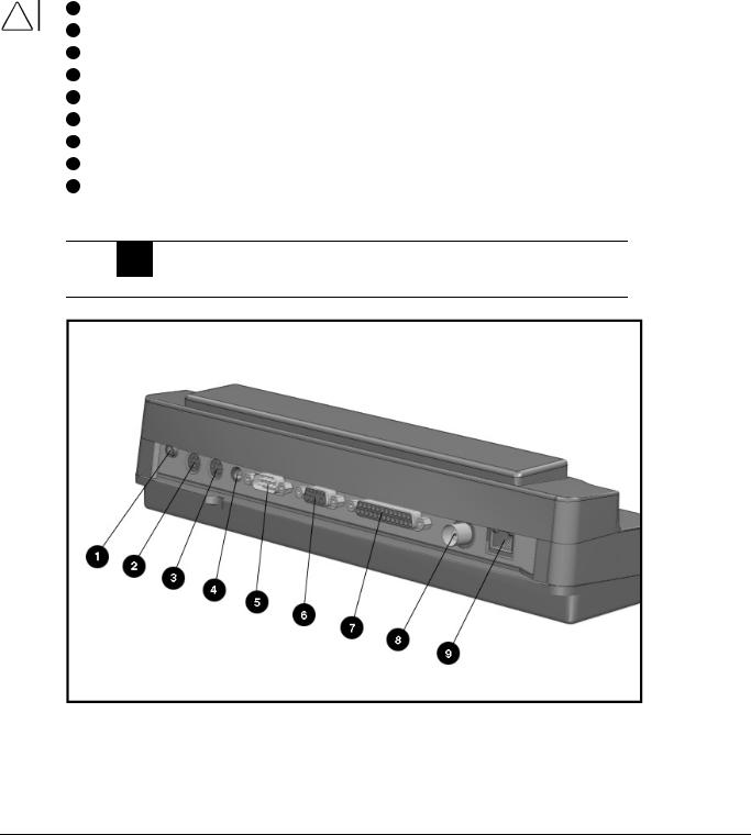
1.7Convenience Base Connectors
The convenience base connectors are shown in the following figure and are identified in this section:
1Stereo speaker connector
2External keyboard
3Mouse
4AC power
5Serial port
6Monitor
7Parallel port
8BNC (thin coaxial cable) connector*
9RJ-45 connector*
*These connectors are available on the convenience base with Ethernet capability.
WARNING: To reduce the risk of electrical shock, fire or damage to the ! equipment, do not plug telecommunications/telephone connectors into the
Network Interface Card (NIC) receptacles.
Figure 1-9. Convenience Base Components
Product Description 1-17

. . . . . . . . . . . . . . . . . . . . . . . . . . . . . . . . . . . . .
1.8Design Overview - Computer
This section presents a design overview of the 4100 and 4200 Families. The overview is limited to field replaceable parts. All replacement parts are listed in Chapter 3. Removal and replacement procedures are presented in Chapter 5.
The computer is a traditional clamshell design with a display unit attached to a system unit. The computer opens to reveal a backlighted LCD display and a full-sized keyboard. The display is designed for a continuously adjustable tilt angle. The system unit houses the keyboard, I/O ports, operator controls and indicators, and DualBay devices.
1.8.1System Unit
The system unit contains the following field-replaceable parts:
■System board
■Processor board
■Display assembly
■CPU/keyboard cover
■Internal microphone
■Optional memory expansion boards
■Lithium Real Time clock battery
■Hard drive
■Diskette drive
■Handle
■Pointing device
■CPU base cover
■PCMCIA assembly
1.8.2System Board
The Compaq Armada system electronics are integrated on two printed circuit assemblies; the system board and the processor board. The 4100 system boards are not compatible with the 4200 Family system boards. Similarly, the 4200 system boards are not compatible with the 4100 Family.
1-18 Product Description

. . . . . . . . . . . . . . . . . . . . . . . . . . . . . . . . . . . . .
1.8.3Processor Board
Prior to the 4150 model, there are two processor board PCAs with either 8-MB or 16-MB of memory and with a level-2 cache populating the models with 100-, 120and 133-MHz processors. The MMX processor on the 4150 , 4150T, and 4160T are P55CLM processors operating at 150 or 166 MHz. These processors are not compatible with 4131T, 4130T, 4120T, 4120, 4110, and 4100 models.
In each of the 4100 and 4200 systems there are two processor board PCAs with a level- 2 cache. The processor board contains the CPU, the OPTi 82C557 system Controller, the OPTi 82C556 data buffer controller, and, if populated on the PCB, cache data RAM. Also mounted on the processor board is an electronic temperature sensor that interfaces to the system through the I2C bus.
The 4210T and 4220T processor boards include the 233and 266-MHz MMX processors and the MTXC controller, part of the Intel 430TX mobile chipset. The 4200 Family processor boards also include the electronic sensor that interfaces to the system through the I2C bus.
1.8.4Processor
The P54LM and the P55CLM Intel Pentium processors are fully compatible with the entire installed base of applications for DOS, Windows, and OS/2, branch predition, and separate code and data caches all provide increased performance over previous x86 processors.
Reduced voltage operation and enhanced SL power management features provide significant power savings over other Pentium versions.
For the 4200 Family, the 233 MHz CPU core runs on a 1.8 V supply. The 266 MHz CPU core runs on a 2.0 V supply. The interface for the 4200 Family is 2.5 V to 3.3 V.
For the 4100 Family, the CPU core runs on a 2.9V supply for lower power operation, while the I/O buffers are powered at 3.3V for compatibility with the rest of the system.
1.8.5System Memory
See Tables 1-1 and 1-2 for the system memory contained on models for the 4100 and 4200 Families. Up to 96-MB of expansion memory is available. Base memory is onboard memory built into the system I/O board. Expansion memory consists of memory expansion board kits available as user installable options.
1.8.6Cache
The 4200 Family models have 256-KB or 512-KB of cache data RAM and 64-KB of cache tag RAM if populated on the PCB are mounted on the processor module.
The 4110-4160T models have 256-KB of cache data RAM and 32-KB of cache tag RAM if populated on the PCB are mounted on the processor module.
Product Description 1-19

. . . . . . . . . . . . . . . . . . . . . . . . . . . . . . . . . . . . .
1.8.7Local Bus Video
The standard Compaq Armada video subsystem consists of:
■An internal LCD display.
■One Megabyte frame buffer (Two Megabyte frame buffer for the 42210T and 4220T)
■An inverter to supply AC power to the LCD back-light system
■A standard external VGA connector for use with CRTs and other VGA compatible displays
■32-KB of video ROM (44KB of video ROM for the 4210T aand 4220T)
■NTSC/PAL encoder
1-20 Product Description

. . . . . . . . . . . . . . . . . . . . . . . . . . . . . . . . . . . . .
Chapter 2
Troubleshooting
This chapter contains troubleshooting information for the computer and the convenience base. The basic steps in troubleshooting the computer include:
1.Completing the preliminary steps listed in Section 2.1.
2.Running the Power-On Self-Test (POST) as described in Section 2.2.
2.Running Computer Setup as described in Section 2.5
4.Running the Computer Checkup (TEST) as described in Section 2.5.
5.Performing the recommended actions described in the diagnostic tables in Section 2.6 if you are unable to exercise POST or Computer Checkup or if the problem persists after running POST and Computer Checkup.
Follow these guidelines when troubleshooting:
■Complete the recommended actions in the order in which they are given.
■Repeat POST and Computer Checkup after each recommended action until the problem is resolved and the error message does not return.
■Once the problem is resolved, do not complete the remaining recommended actions.
■Refer to Chapter 5 for any removal and replacement procedures.
■If the problem is intermittent, check the computer or convenience base several times to verify that the problem is solved.
Use the following table for quick reference to troubleshooting information:
If You Want To: |
Run: |
|
|
Check for POST error messages |
POST |
|
|
Check that computer components are recognized and |
Computer Checkup (TEST) under Compaq |
running properly |
Utilities |
|
|
View information about the computer and installed or |
View System Information |
connected devices |
(INSPECT)under Compaq Utilities |
|
|
Perform any of the following: |
Computer Setup |
„ Check the system configuration |
|
„ Set the system power management |
|
parameters |
|
„ Return the system to its original |
|
configuration |
|
„ Check system configuration of installed devices |
|
|
|
Troubleshooting 2-1

. . . . . . . . . . . . . . . . . . . . . . . . . . . . . . . . . . . . .
2.1 Preliminary Steps
IMPORTANT: Use AC Power when running POST, Computer Setup, or Computer Checkup. A low-battery condition could initiate Suspend or Hibernation and interrupt the test.
Before running POST and Computer Checkup, complete the following steps:
1.Obtain established passwords. If you must clear the passwords, go to Section 2.2.
2.Ensure that the hard drive is installed in the computer.
2.Ensure that the battery pack is installed in the computer and the AC power is connected to the computer and plugged into an AC power source.
4.Turn on the computer.
5.If a power-on password has been established, type the password and press Enter.
NOTE: The key icon appears on the display when the computer is turned on to indicate that QuickLock/QuickBlank has been initiated. Type the power-on password to
exit QuickLock/QuickBlank. If the password is unknown, it must be cleared (see Section 2.2).
6.Run Computer Setup (Section 2.5).
7.Use the Hotkeys to adjust the contrast (Fn+F9) and brightness (Fn+F10) to the center of their ranges and leave the display open. On models with color TFT displays, contrast is not applicable.
8.Turn off the computer and all external devices.
9.Disconnect any external devices that you do not want to test. If you want to use the printer to log error messages, leave it connected to the computer.
NOTE: If a problem only occurs when an external device is connected to the computer, the problem could be with the external device or its cable. Isolate the problem by running POST with and without the external device connected.
10.Use Advanced Diagnostics and loopback plugs in the serial and parallel connectors if you plan to test these ports. You may run Advanced Diagnostics from the hard drive or from a diskette.
If you are running Diagnostics from the hard drive, complete the following steps:
a.Turn on or restart the computer.
b.Press F10 when the cursor appears in the upper right corner of the screen. If you do not press F10 in time, restart the computer and try again. The Welcome screen appears.
2-2 Troubleshooting
 Loading...