


R
Table of Contents
DTV-102
Table Of Contents |
|
|
1 |
Introduction..................................................................................................................... |
1 |
1.1 |
Safety and Product Information...................................................................................... |
1 |
1.2 |
Important Safety Instruction............................................................................................ |
2 |
1.3 |
Board Level Description................................................................................................. |
3 |
1.4 |
Remote Control Description........................................................................................... |
4 |
1.5 |
Unit Description.............................................................................................................. |
6 |
2 |
Installation...................................................................................................................... |
7 |
2.1 |
Setup Checklist.............................................................................................................. |
7 |
2.2 |
Unpacking...................................................................................................................... |
7 |
2.3 |
Cable Connections......................................................................................................... |
8 |
2.4 |
Remote Control Battery Installation.............................................................................. |
10 |
2.5 |
Initial Setup................................................................................................................... |
10 |
3 |
Basic Operation............................................................................................................ |
11 |
3.1 |
Initial Channel Scan...................................................................................................... |
11 |
3.2 |
Changing Channels...................................................................................................... |
12 |
3.3 |
Audio and Language Control........................................................................................ |
13 |
3.4 |
Information Display....................................................................................................... |
14 |
4 |
Menu Operation............................................................................................................ |
16 |
4.1 |
Channel Menu Features............................................................................................... |
16 |
4.2 |
Option Menu Features.................................................................................................. |
19 |
4.3 |
Lock Menu Features. .................................................................................................. |
25 |
5 |
Reference..................................................................................................................... |
32 |
5.1 |
Troubleshooting Guide................................................................................................. |
32 |
5.2 |
Specifications .............................................................................................................. |
33 |
Please read this manual before connection and use.
Introduction
This User Guide provides detailed information to correctly setup and evaluate the DTV-102 Converter Box.
A procedure is described to setup the converter box for normal operation using the provided GUI software, with details for evaluation of the many provided features.
1.1 Safety and Product Information
Warning: Use only the provided AC100~240V, 50Hz/60Hz power supply.
Warning: To prevent damage which may result in fire or electric shock hazard, do not expose this module to rain or moisture, or use it near water.
Caution: Outdoor Antenna Grounding - If an outside antenna is connected to the product, be sure the antenna is grounded so as to provide some protection against voltage surges and built-up static charges. Article 810 of the National Electric Code, ANSI/NFPA 70, provides information with regard to proper grounding of the mast and supporting structure, grounding of the lead-in wire to antenna discharge unit, size of grounding conductors, location of antenna-discharge unit, connection to grounding electrodes, and requirements for the grounding electrode.
WARNING: TO REDUCE THE RISK OF FIRE OR ELECTRIC SHOCK, DO
NOT EXPOSE THIS APPLIANCE TO RAIN OR MOISTURE.
The lightning flash with arrowhead symbol, within an equilateral triangle, is intended to alert the user to the presence of uninsulated “dangerous voltage” within the product’s enclosure that may be of sufficient magnitude to constitute a risk of electric to persons.
The exclamation point within an equilateral triangle is intended to alert the user to the presence of important operating and maintenance (servicing) instructions in the literature accompanying the appliance.
Introduction
1.2 Important Safety Instruction
•Read these instructions. Heed all warnings.
•Do not use near water.
•Clean only with dry cloth.
•Do not block any ventilation openings. Maintain well ventilated conditions around the roduct. Do not put product on bed, sofa or anything that blocks ventilation. Install according to instructions.
•Do not install near any heat sources such as radiators, heat registers, stoves, or other apparatus (including amplifiers) that produce heat.
•Do not defeat the safety purpose of the polarized or grounding-type plug. A polarized plug has two blades with one wider than the other. If the provided plug does not fit into your
outlet, consult an electrician for replacement of the obsolete outlet.
•Only use attachments/accessories specified by the manufacturer.
•Use only with the cart, stand, tripod, bracket, or table specified by the manufacturer, or sold with the apparatus. When a cart is used, use caution when moving the cart/apparatus combination to avoid injury from tip-over.
•Unplug this apparatus during lightning storms or when unused for long periods of time.
•Refer all servicing to qualified service personnel. Servicing is required when the apparatus has been damaged in any way, such as plug is damaged, liquid has been spilled or objects have fallen into the apparatus, the apparatus has been exposed to rain or moisture, does not operate normally, or has been dropped.
•Apparatus shall not be exposed to dripping or splashing and no objects filled with liquids, such as vases, shall be placed on the apparatus.
•Do not perform any servicing other than that contained in the operating instructions unless you are qualified to to so.
- 1 - |
- 2 - |
|||
|
|
|
|
|
Introduction
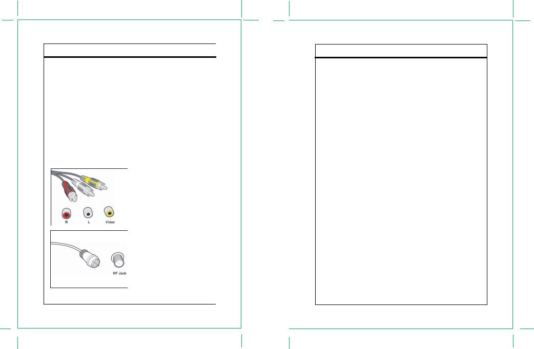
1.3 Board Level Description
The DTV-102 supports one input and two outputs. The input is a standard RF connector, which can be connected to an antenna with a coaxial cable. The outputs are standard NTSC composite video and left/right audio outputs, with RCA jack connectors, and a standard RF output; both are provided to insure an easy connection to any analog TV. The RF output provides video modulated on Channel 3 or Channel 4, as selected by the on-board switch.
The Audio/Video (A/V) cables provide good picture quality and stereo sound, and should be used if available on the TV. The A/V jacks are color coded (yellow for video, red for right audio and white for left audio). If the TV has only one input for audio (mono), connect it to the left (white) audio jack on the converter box (CB) .
The RF jack and coaxial cable provide acceptable picture and mono sound quality. It should be used if A/V connections are not available on the TV. RF jacks are typically used to connect your TV to terrestrial antenna sources.
Note: Be sure to use RG-6 coaxial cable when connecting from the antenna to the CB module.
Figure1. Connectors
Introduction
The module also includes an infra-red (IR) receiver and three push buttons to provide front panel control for the
power on/off and channel up/down functions.
The only one LED indicates three possible power states for the converter box:
• |
Powered on and functional |
Bright Green LED is ON |
• |
In stand-by mode |
Dim Red LED is ON |
• |
Powered off |
Red LED is OFF. |
- 3 - |
- 4 - |
|||
|
|
|
|
|
Introduction
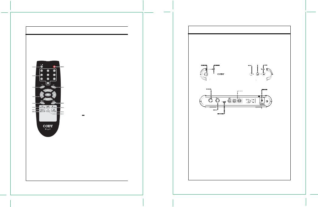
1.4 Remote Control Description
Key Description
A description of the remote control button functions is shown in Figure 2 below.
1 |
|
9 |
2 |
|
|
3 |
|
10 |
4 |
|
|
5 |
|
11 |
6 |
|
12 |
7 |
|
13 |
8 |
|
|
|
|
14 |
|
|
|
Figure 2. Remote Control
Button Functions
1.AUDIO
Press to set the audio mode.
2.Number keypad
Press to input data.
3.ZOOM
Press to zoom the image.
4.Direction Buttons & MENU
While working with the system menu, press the direction buttons to move between the options. The up/down direction button works also as the channel+/- button.
Press MENU to display the menu.
5.ENTER
Press to confirm settings.
6.GUIDE
Press to show the program guide.
7.Q.VIEW
Press to view the previous channel.
8.SIGNAL
Press to display the signal quality information.
9.POWER
Press to turn on/off the player.
10.Button
Press to display the digital input field.
11.EXIT
Press to back up/exit the menu.
12.INFO
Press to show the current working status.
13.CH-LIST
Press to show the channel list.
14.CCD
Press to set the closed caption.
Introduction
1.5 Unit Description
A description of the buttons and the connectors on the main unit is shown in Figure 3 below.
Figure 3. Buttons on the Main Unit
Power |
|
|
Power Indicator |
Remote Sensor |
CH - |
CH+ |
|
|
|
|
|
|
|
|
|
|
|
|
|
|
|
|
|
|
|
|
|
|
|
|
|
|
|
|
|
|
|
|
|
|
|
|
|
|
|
|
|
|
|
|
|
|
|
|
|
|
|
|
|
|
|
|
|
|
|
|
|
|
|
|
|
RF Signal In |
Power Cord |
RCA Output
RF Signal Out
Channel Selector
POWER
Press to turn the unit on/off.
CHANNEL +/-
Press to skip channels.
Power Indicator
Under the normal working mode, it lights green. Under the standby mode, it lights red.
Remote Sensor
Sense the remote signal.
RF Signal In
RF IN connector
RF Signal Out
RF OUT connector
Channel Selector
Switch between the channel 3 and the channel 4
Power Cord
Plug into the power supply.
- 5 - |
- 6 - |
|||
|
|
|
|
|

Installation
2.1 Setup Checklist
The required hardware and equipment necessary to use the DTV-102 are:
-DTV-102 converter box
-Converter box remote control and 2 AAA batteries
-RF cable for output
-Composite video and audio cables, or RF cable, for output
-RF video source (terrestrial antenna)
-Analog TV with composite video/audio or RF input
2.2Unpacking
The following items are included with your product. If any items are missing, contact your dealer.
Main Unit
Remote
RCA Cable
RF Cable
Installation
2.3 Cabel Connections
Figure 4. Cable Connections
|
|
|
|
|
|
|
|
|
|
|
|
|
|
|
|
|
|
|
|
|
|
|
|
|
|
|
|
|
|
|
|
|
|
|
|
|
|
|
|
|
|
|
|
|
|
|
|
|
|
|
|
|
|
|
|
|
|
|
|
|
|
|
|
|
|
|
|
|
|
|
|
|
|
|
|
|
|
|
|
|
|
|
|
|
|
|
|
|
|
|
|
|
|
|
|
|
|
|
|
|
|
|
|
|
|
|
|
|
|
|
|
|
|
|
|
|
|
|
|
|
|
|
|
|
|
|
|
|
|
|
|
|
|
|
|
|
|
|
|
|
|
|
|
|
|
|
|
|
|
|
|
|
|
|
|
|
|
|
|
|
|
A |
|
|
|
|
|
|
|
|
|
|
|
|
|
|
|
B |
|
|
|
|
|
|
||||
|
|
|
|
|
|
|
|
|
|
|
|
|
|
|
|
|
|
|
|
|
||||||
|
|
|
|
|
|
|
|
|
|
|
|
|
|
|
|
|
|
|
|
|
|
|
|
|
|
|
To Wall Outlet
MONITOR WITH AV /RF INPUT
NOTE: Set the external receiver to the relative input mode to enable the signal pass. When output signal, refer to the user’s manual of the external receiver as well.
Input the TV signal to your converter box
Connect the RF source to the RF IN connector located on the unit’s rear panel. To view television channels, a
signal must be received by the device from one of the following sources: The internal antenna/An outdoor aerial
antenna/A cable television network/A satellite network.
RF IN
- 8 -
- 7 -
Installation
Output the TV signal from your converter box to the external receiver
You can adopt either of the methods below to output the TV signal to the external monitor. Refer to A,B in the Figure 4. for better understanding.
A.CVBS Output
Connect the video port (VIDEO) by the supplied RCA cable. (yellow plug). Connect the audio port (L, R) by the supplied RCA cable (white&red plug).
B.RF Output
Connect the RF OUT port by the RF cable to output the TV signal.
NOTE: Only two channels are available if you chose to output the signal by the RF cable.
Slide the channel switch on the unit’s rear panel to select the channel 3 or the channel 4. Left Position - - CH3 Right Position - - CH4
C.Analog pass-through Application
-Power On : User Setting the A/V and Modulator 3/4Ch Output
-Power Off : User Setting the analog pass-through Output
1) Power On Application
Analog Signal
Digital Signal
Ant In |
MD 3/4Ch |
Composite Video Output
Audio L/R
ANT IN ANT OUT |
Audio-R Audio-L Video OUT |
2) Power Off Application
|
|
|
|
|
|
|
Receive the Analog Signal |
Analog Signal |
|
|
|
|
|
|
|
|
|
|
|
|
|
|
|
Digital Signal |
Ant In |
|
Loop-through |
||||
|
|
|
|
|
|
Signal |
|
|
|
|
|
|
|
|
|
|
|
|
ANT IN |
ANT OUT |
Audio-R Audio-L Video OUT |
||
Power Connection
Insert the power plug into the wall outlet with AC100V-240V, 50Hz/60Hz.
NOTE: Be sure to have all necessary cable connections properly done before connect the power source.
If the player will not be used for a long period of time, disconnect the power and remove the batteries from the remote.
Installation
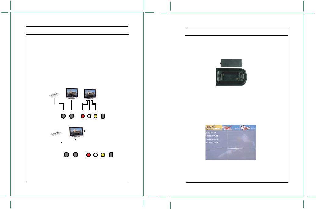
2.4 Remote Control Battery Installation
1.Unlatch the battery compartment cover on the back of the remote control.
2.Insert 2 AAA batteries into the battery compartment, making sure the + and – ends of each battery line up with the corresponding marks in the battery compartment, as shown in Figure 5 below.
3.Snap the cover back on to the remote control.
Figure 5. Install Remote Control Batteries
2.5 Initial Setup
After the input/output connections have been made, and the DTV-102 has been powered up, a blue screen should be seen on the TV screen. Pressing the MENU button on the remote control should display the main menu on the screen, as shown in Figure 6 below. Chapter 3 in this User Guide describes the procedures for basic TV operations such as scanning for channels, changing channels, language control, and information display. Refer to Chapter 4 for more details about all of the Menu features and controls.
Figure 6. Main Menu
- 9 - |
- 10 - |
|
 Loading...