


English |
Owner’s manual
APX2180
APX4360
DPX2250
DPX1800
DPX11500
APX AND DPX AMPLIFIERS
APX/DPX Amplifiers |
|
1 |
APX-DPXOwnersManual.pmd |
1 |
2006-03-14, 21:46 |

English
Thank you for purchasing this Clarion product.
•Please read this owner’s manual in its entirety before operating this equipment.
•After reading this manual, keep it handy, such as in your glove compartment.
•Save your sales receipt. The warranty at the end of this manual and your sales receipt are essential for warranty service.
FCC Approval
This equipment has been tested and found to comply with the limits for a Class B digital device, pursuant to Part 15 of the FCC Rules. These limits are designed to provide reasonable protection against harmful interference in a residential installation. This equipment generates, uses, and can radiate radio frequency energy and, if not installed and used in accordance with the instructions, may cause harmful interference to radio communications. However, there is no guarantee that interference will not occur in a particular installation. If this equipment does cause harmful interference to radio or television reception, which can be determined by turning the equipment off and on, the user is encouraged to consult the dealer or an experienced radio/TV technician for help.
2 |
APX/DPX Amplifiers |
APX-DPXOwnersManual.pmd |
2 |
2006-03-14, 21:46 |

Contents |
|
1. FEATURES ............................................................................................................. |
4 |
2. PRECAUTIONS ...................................................................................................... |
5 |
Installation .............................................................................................................. |
5 |
3. CONTROLS ............................................................................................................ |
6 |
4. OPERATIONS ......................................................................................................... |
8 |
Setting input voltage .............................................................................................. |
8 |
Setting the operating level ..................................................................................... |
8 |
Improving bass sound ............................................................................................ |
8 |
Matching subwoofer output to mid-range speakers .............................................. |
9 |
Connecting directly to a head unit ......................................................................... |
9 |
Care and maintenance .......................................................................................... |
9 |
5. INSTALLATION AND WIRING .............................................................................. |
10 |
What is included in the box .................................................................................. |
10 |
Mounting precautions .......................................................................................... |
10 |
Wiring precautions ............................................................................................... |
11 |
Power and speaker connections .......................................................................... |
13 |
Applications .......................................................................................................... |
15 |
DPX1800 and DPX11500 stackable configurations ........................................... |
19 |
Setting the gain .................................................................................................... |
19 |
Adjusting the crossover ........................................................................................ |
20 |
Setting the bass boost .......................................................................................... |
20 |
Final system checks ............................................................................................. |
20 |
6. TROUBLESHOOTING .......................................................................................... |
21 |
Indicator lights ...................................................................................................... |
21 |
No audio ............................................................................................................... |
21 |
Amplifier shuts down after playing for a period of time ........................................ |
22 |
Distorted audio ..................................................................................................... |
22 |
Amplifier fuse keeps blowing ............................................................................... |
22 |
Whining noise when engine on ........................................................................... |
22 |
Ticking noise when engine on ............................................................................. |
23 |
7. GLOSSARY .......................................................................................................... |
23 |
8. SPECIFICATIONS ................................................................................................ |
24 |
APX Amplifiers ..................................................................................................... |
24 |
DPX Amplifiers ..................................................................................................... |
25 |
9. LIMITED WARRANTY INFORMATION ................................................................. |
26 |
APX/DPX Amplifiers |
3 |
English
APX-DPXOwnersManual.pmd |
3 |
2006-03-14, 21:46 |

English
1.FEATURES
The Clarion APX2180, APX4360, DPX2250, DPX1800 and DPX11500 amplifiers fit a variety of system configurations and provide these features:
•IVS - Input Voltage Selector with three sensitivity ranges on the gain control for the ability to connect to almost any source
•PFS - Precise Frequency Selector, a detented crossover frequency adjustment
•Ground loop isolation for RCA inputs
•Full frequency response with low distortion and exceptional signal-to-noise performance
•Advanced circuitry design provides bridgeable outputs for use in a variety of applications
•Independent electronic crossovers to aid in audio system design
The DPX1800 and DPX11500 each have 24dB per octave slope and full adjustment range from 30Hz to 250Hz.
The APX2180, APX4360, and DPX2250 each have 12dB per octave slope and full adjustment range from 50Hz to 550Hz.
•Bass boost circuit on APX series amps to reinforce low frequency signals
•Remote turn-on with “soft start” muting to prevent turn-on “thump”
•Protection circuits for overheating and speaker shorts
•APX2180, APX4360 and DPX2250 are 2-Ohm load capable of driving a variety of speaker systems
•DPX1800 and DPX11500 are 1-Ohm load capable to drive a variety of subwoofers
•Gold-plated input/output connectors and on-board automotive-type fuses
•Aluminum heat sink for efficient heat dissipation
•Low profile, compact footprint to accommodate space limitations
•SLI - Speaker Level Inputs on amps for integration with factory sound systems
•SSF - Adjustable subsonic filter on the DPX1800 and DPX11500 can be turned down to 10Hz
•Automatic load-sensing circuit (full power into 1 or 2 Ohms) on the DPX1800 and DPX11500
4 |
APX/DPX Amplifiers |
APX-DPXOwnersManual.pmd |
4 |
2006-03-14, 21:46 |

• Do not disassemble or modify this product. |
|
English |
2.PRECAUTIONS |
|
|
• Do not operate this product in ways other than those described in this manual. |
|
|
|
|
|
• Do not pour liquid or poke foreign objects into the unit. Water and humidity will |
|
|
damage internal circuitry. |
|
|
• If the unit becomes wet, turn off all power and ask your authorized Clarion dealer |
|
|
to clean or service the unit. |
|
|
Failure to observe these precautions may damage your car or the amplifier, and may |
|
|
void the warranty. |
|
|
WARNING
Exposure to continuous sound levels of 85dB or higher may result in hearing loss. Although Clarion products are capable of producing high sound pressure levels, please use your product at reasonable levels.
While operating your vehicle, please observe all local sound ordinances for your safety.
Installation
Installation of mobile audio and video components requires experience with a variety of mechanical and electrical procedures. Although this manual provides general installation and operation instructions, it does not show the exact installation methods for your particular vehicle.
If you do not have the required knowledge and experience to successfully complete the installation, consult an authorized Clarion dealer about professional installation options.
APX/DPX Amplifiers |
5 |
APX-DPXOwnersManual.pmd |
5 |
2006-03-14, 21:46 |

English
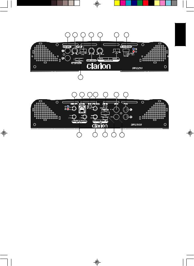
3. CONTROLS
1 |
4 |
2 |
6 |
3 |
8 |
9 |
5 |
7
APX2180 signal connections and audio adjustments
1 |
4 |
2 |
6 |
5 |
7 |
3 |
9 |
3 |
8 |
9 |
APX4360 signal connections and audio adjustments |
|||||
1. RCA input jacks |
|
|
6. BBC (Basic Boost Control) |
||
2. IVS (Input Voltage Selector) |
|
|
7. |
SLI (Speaker Level Input) connector |
|
3. PFS (Precise Frequency Selector) |
|
8. Crossover frequency multiplier |
|||
4. Gain control |
|
|
9. |
Crossover function switch |
|
5. Output mode switch |
|
|
|
|
|
6 |
APX/DPX Amplifiers |
APX-DPXOwnersManual.pmd |
6 |
2006-03-14, 21:46 |
1 |
6 |
2 |
4 |
3 |
10 |
9 |
5
DPX2250 signal connections and audio adjustments
11 8 7 3 14 12 1
English
|
4 |
6 |
2 |
5 |
13 |
|
DPX1800 and DPX11500 signal connections and audio adjustments |
||||
1. |
RCA input jacks |
|
8. RLC (Remote Level Control) port |
||
2. IVS (Input Voltage Selector) |
|
9. Output mode switch |
|||
3. |
PFS (precise Frequency Selector) |
|
10. |
Crossover function switch |
|
4. |
BBS (Bass Boost Control |
|
11. Subsonic filter frequency selector |
||
5. |
SLI (Speaker Level Inputs) |
|
12. |
Slave RCA jack |
|
6. |
Gain control |
|
13. RCA output jack |
||
7. |
PCS (Polarity Control Switch) |
|
14. |
Master/Slave selector |
|
APX/DPX Amplifiers |
7 |
APX-DPXOwnersManual.pmd |
7 |
2006-03-14, 21:46 |

English
4.OPERATIONS
Selecting input voltage
APX and DPX amplifiers accommodate a wide range of signal input voltages (0.2V to 8V). This wide range is split up into three ranges, which are accessible through switches located in the “Gain” area of the amplifier.
•0.2V-0.6V selects an input sensitivity range between 200mV and 600mV.
•0.6-2V selects an input sensitivity range between 600mV and 2V.
•2V-8V selects an input sensitivity range between 2V and 8V.
The gain rotary control operates within these voltage windows.
Note:
Most decks, even 4V and 5V units do not operate at full output voltage. This requires the switch to be set in the 0.6-2V range.
Setting the operating level
The gain switches allow you to set the nominal operating level of the amplifier from 0.2 to 8V for RCA inputs or 500mV to 5V for speaker level inputs. This wide adjustment range accommodates virtually any source unit brand.
Once you set the correct range using the IVS, you must adjust the gain to match the amplifiers sensitivity to that of the source unit. The gain control is not a volume control. It exists only to allow an amplifier to be used with different models and brands of head units.
Improving bass sound
The amplifiers feature a narrow-frequency band bass boost circuit (known as “high- Q”). Acting much like an equalizer, the bass boost control lets you tune low-frequency audio response to compensate for a less than ideal subwoofer enclosure design. The added boost produces rich, full bass tones that are normally difficult to reproduce in the car audio environment.
•The APX2180, APX4360, and DPX2250 have a switchable gain that is fixed at 45Hz. If you don’t want to boost the bass frequencies, set this control to “OFF.”
•The DPX1800 and DPX11500 have a variable-frequency bass boost control from 30Hz to 125Hz. They do not have a bass boost on/off switch, but a level control that goes from 0dB to 15dB.
CAUTION
This control can dramatically increase the power output level and could cause speaker damage if you over use it.
8 |
APX/DPX Amplifiers |
APX-DPXOwnersManual.pmd |
8 |
2006-03-14, 21:46 |

Matching subwoofer output to mid-range speakers
The DPX1800 and DPX11500 feature a polarity control switch for reversing the polarity of the output signal. This can be useful when matching the acoustic output of your subwoofers to the output of your mid-range speakers.
Connecting directly to a head unit
The amps provide connections directly to a head unit without a pre-amp output, such as a factory-installed head unit.
WARNING
When using the speaker (high-level) inputs, the black wire must be grounded at the radio. Failure to do so will result in noise and/or improper operation.
Care and maintenance
Cleaning the case
Use a soft, dry cloth to gently wipe dust and dirt from the unit.
Do not use benzene, thinner, car cleaner, or other cleaners. These substances may damage the unit or cause the paint to peel.
Servicing the unit
In the event that trouble arises, never open the case or disassemble the unit. The internal parts are not serviceable by the user. Opening any components will void the warranty.
CAUTION!
Changes or modifications to this product not approved by the manufacturer will void the warranty and will violate FCC approval.
APX/DPX Amplifiers |
9 |
English
APX-DPXOwnersManual.pmd |
9 |
2006-03-14, 21:46 |
 Loading...