


apx-dpx-update.qxp 8/18/2004 8:46 AM Page 1
APX640.4/APX640.2/APX320.2/DPX1001.1
apx-dpx-update.qxp 8/18/2004 8:46 AM Page 2


 APX640.4/640.2/320.2/DPX1001.1
Dear Customer,
Congratulations on your purchase of the world’s finest brand in the mobile electronic industry. At Clarion we are committed to high-quality music reproduction, and we are confident that you will be pleased with your purchase. Clarion’s extensive history in the mobile electronic industry translates into products that are built to the highest of standards. These products provide optimum performance, which we are sure you will enjoy for years to come. Thank you for making Clarion your car audio brand.
For maximum performance Clarion recommends having your amplifier installed by an authorized Clarion dealer. Please read your warranty statement and retain your original sales receipt as proof of purchase.
To learn more about Clarion’ complete line of car audio products, please visit us at our Web site
www.clarion.com
WARNING
Exposure to continuous sound levels of 85dB or higher may result in hearing loss. Clarion products are capable of producing high sound pressure levels, but please use your product at reasonable levels. Please observe all local sound ordinances for your safety during the operation of your vehicle.
INTRODUCTION
2

apx-dpx-update.qxp 8/18/2004 8:46 AM Page 3
Owner’sManual
TABLE OF CONTENTS
Introduction . . . . . . . . . . . . . . . . . . . . . . . . . . . . . . . . . . . . . . . . . 2
Description . . . . . . . . . . . . . . . . . . . . . . . . . . . . . . . . . . . . . . . . . 3
Installation, Mounting/Wiring Precautions . . . . . . . . . . . . . . . . . 4
Input Connections and Audio Control . . . . . . . . . . . . . . . . . . . . 5-8
Connections for Power and Speakers . . . . . . . . . . . . . . . . . . . . . 9-10
Applications . . . . . . . . . . . . . . . . . . . . . . . . . . . . . . . . . . . . . . . . 11-14
Setting the Gain, Crossover/Bass Boost . . . . . . . . . . . . . . . . . . . 15
Final System Checks, Troubleshooting . . . . . . . . . . . . . . . . . . . . 16
Product Specs . . . . . . . . . . . . . . . . . . . . . . . . . . . . . . . . . . . . . . . 17
Warranty Information . . . . . . . . . . . . . . . . . . . . . . . . . . . . . . . . . 18
DESCRIPTION
Clarion has crafted its car audio amplifier to fit a variety of system configurations. The following is a list of features:
•Full frequency response with low distortion and exceptional signal-to-noise performance.
•Advanced circuitry design features bridgeable outputs for use in a variety of applications.
•Independent electronic crossovers, each with a 12dB (12/24dB - DPX1001.1) per octave slope and full adjustment range from 50Hz to 5.8KHz, (50Hz to 580Hz - DPX1001.1) to aid in audio system design.
•Bass boost circuit to reinforce low frequency signals that may be lost due to subwoofer box design.
•Adjustable input level controls with ground loop isolation, accepting a wide range of input signals.
•Remote turn-on with “soft start” muting to prevent turn-on “thump”.
•Protection circuits for overheating and speaker shorts.
•2-ohm load capable to drive a variety of speaker systems.
•Gold-plated input/output connectors and an external automotivetype fuse.
•Aluminum heat sink for efficient heat dissipation.
•Low profile, compact size to accommodate space limitation.
DESCRIPTION
3

apx-dpx-update.qxp 8/18/2004 8:46 AM Page 4


 APX640.4/640.2/320.2/DPX1001.1
INSTALLATION
This section lists mounting and wiring precautions prior to installing the Clarion amplifier. These safeguards provide enough detail to complete an installation successfully. Do not attempt to install the amplifier yourself, if you do not have the necessary skills. Instead, see your authorized Clarion dealer for installation recommendations.
MOUNTING PRECAUTIONS
Although the Clarion amplifiers incorporate heat sinks and protection circuits, mounting the amplifier in a tight space without any air movement will result in damage to the amp’s internal circuitry over time. Choose a site that provides adequate ventilation around the amplifier. For easy system setup, mount the amplifier so the frontpanel controls are accessible after installation.
In addition, observe the following precautions:
1.For the most efficient cooling, mount the amplifier so cool air runs along the length of the fins rather than across them. Remember, any moving air will dissipate heat.
2.Mount the amplifier on a rigid surface. Avoid mounting to subwoofer enclosures or areas prone to vibration. Do not install the amplifier on plastic or other combustible materials.
3.Prior to drilling, make sure proposed mounting holes will not cut into the fuel tank, fuel lines, brake lines (under chassis), or electrical wiring.
WIRING PRECAUTIONS
Read all wiring precautions. If you are not sure of the connections, contact your authorized Clarion dealer.
1. Before installation, make sure the source unit’s Power switch is in the OFF position.
2. Disconnect the negative (-) lead of the battery before making any power connections.
3. When making connections, be sure that each connection is clean and secure. Insulate final connections with electrical tape or shrink tubing. Failure to do so may result in damage to your equipment.
PRECAUTIONS |
4. A secure, clean ground connection is critical to the performance of your Clarion |
|
|
|
amplifier. Use the shortest ground wire possible and securely connect to the vehicle’s |
|
chassis to minimize resistance and avoid noise problems. Be sure to clean off any |
|
paint prior to making this connection. |
|
5. Add an external fuse on the amplifier’s positive (+) power lead and connect it as |
|
close as possible to the vehicle’s (+) battery terminal. Use a fuse rated to the total cur- |
|
rent consumption of the amplifier(s). Adding an external fuse will protect the electri- |
|
cal system from short circuits that can result in a fire. |
4

apx-dpx-update.qxp 8/18/2004 8:46 AM Page 5
Owner’s Manual
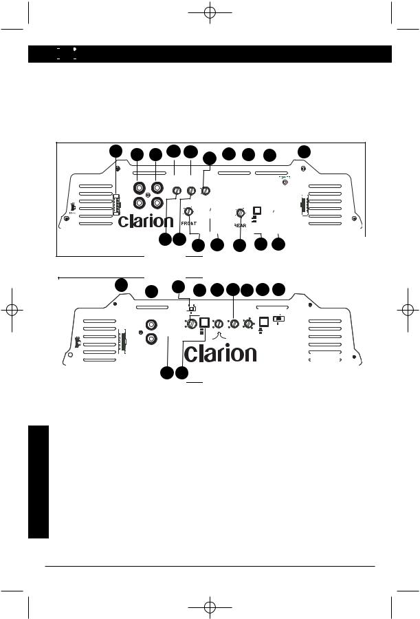
INPUT CONNECTIONS AND AUDIO CONTROL
Clarion amplifiers contain connections for RCA Inputs and Audio Control as shown below.
1 |
4 |
2 |
6 |
|
3 |
8 |
9 |
5 |
7 |
|
|
|
|
|
|
|
|||
INPUT |
|
|
|
|
CROSSOVER |
|
|
APX320.2 |
|
|
L |
0 |
|
55 |
110 |
|
|
|
|
|
|
|
|
|
|
|
|||
|
|
|
|
240 |
|
|
|
HIGH |
|
|
|
|
|
|
|
|
|
||
|
|
15 |
|
550 |
|
FREQ |
|
|
|
|
|
dB |
330 |
|
|
Level |
|||
|
|
4V-8V |
|
RANGE |
OFF |
L & R (MONO) |
|
||
|
|
|
|
|
X1 |
|
|||
|
|
|
|
Hz |
HP |
BRIDGED (R IN) |
|
||
|
R |
2V-4V |
|
|
X10 |
L |
|||
|
0.2V-2V |
|
|
|
|
LP |
STEREO |
R |
|
Figure 1-1 APX320.2 Input Connections and Audio Control
1 |
4 |
2 |
6 |
|
3 |
8 |
9 |
5 |
7 |
|
|
|
|
|
|
|
|||
INPUT |
|
|
|
|
CROSSOVER |
|
|
APX640.2 |
|
|
L |
0 |
|
55 |
110 |
|
|
|
|
|
|
|
|
|
|
|
|||
|
|
|
|
240 |
|
|
|
HIGH |
|
|
|
|
|
|
|
|
|
||
|
|
15 |
dB |
550 |
330 |
FREQ |
|
|
Level |
|
|
4V-8V |
|
RANGE |
OFF |
L & R (MONO) |
|
||
|
|
|
|
|
X1 |
|
|||
|
|
|
|
Hz |
HP |
BRIDGED (R IN) |
|
||
|
|
2V-4V |
|
|
X10 |
L |
|||
|
R |
|
|
LP |
STEREO |
||||
|
0.2V-2V |
|
|
|
|
R |
|||
|
|
|
|
|
|
|
|
|
|
Figure 1-2 APX640.2 Input Connections and Audio Control
1. |
RCA Input Jacks |
6. |
Bass Boost Control |
2. |
Input Voltage Selector |
7. |
Speaker Level Inputs |
3. |
Precise Frequency Selector |
8. |
Frequency Multiplier |
4. |
Gain Control |
9. |
X-Over Mode Switch |
5. |
Input Mode |
|
|
CONNECTIONS
5
apx-dpx-update.qxp 8/18/2004 8:46 AM Page 6


 APX640.4/640.2/320.2/DPX1001.1
INPUT CONNECTIONS AND AUDIO CONTROL
Clarion amplifiers contain connections for RCA Inputs and Audio Control as shown below.
CONNECTIONS
17 |
2 |
3 |
|
||
|
INPUT |
|
|
FRONT |
REAR |
|
(2 CH. IN) |
|
HIGH L
Level
+
- L
+ R - R
5 |
6 |
|
15 |
14 |
|
12 |
13 |
|
18 |
|
|
|
|
|
|
|
|||||
0.2V-0.6V |
0.2V-0.6V |
|
|
|
FRONT |
|
|
|
||
0.6V-4V |
0.6V-4V |
|
|
|
|
|
|
|
|
|
2V-8V |
2V-8V |
|
SOURCE |
|
|
|
|
|
||
FRONT |
REAR |
BASS |
|
BRIDGED (F R IN) |
|
APX640.4 |
||||
2 CH. |
|
|
|
|||||||
|
|
|
|
SELECT |
|
STEREO |
|
|
|
|
|
|
|
|
|
|
|
|
|
||
GAIN |
GAIN |
0BOOST |
|
|
|
L & R SUM MONO |
|
|
||
|
|
|
|
2 CH. |
4 CH. |
|
REAR |
|
HIGH |
|
|
|
|
|
|
L & R MONO |
|
Level |
|||
|
|
15 |
dB |
BASS |
|
|
|
BRIDGED (R L IN) |
|
|
|
|
|
|
|
|
FREQ |
STEREO |
|
+ |
|
FREQ Hz |
|
|
FREQ Hz |
|
L |
|||||
|
|
|
|
RANGE |
|
- |
||||
55 |
110 |
|
HP |
|
|
110 |
|
|
+ |
|
|
55 |
|
|
HP |
|
|||||
240 |
|
|
|
R - |
||||||
550 |
|
|
|
240 |
|
|
|
|||
|
|
|
550 |
|
|
|
|
|||
330 |
|
LP OFF |
|
|
X1 |
|
|
|
||
|
|
|
330 |
LP OFF |
|
|
||||
|
|
|
|
|
X10 |
|
|
|||
|
|
|
|
|
|
|
|
|
|
|
20 |
21 |
8 |
23 |
9 |
28 |
24 |
|
|
Figure 2-1 APX640.4 Input Connections and Audio Control
16 |
|
1 |
30 |
19 |
|
15 |
31 |
22 |
25 |
29 |
|
|
|
|
|
||||||||
|
|
|
.2V-.6V 2V-8V |
|
|
|
|
|
|
|
|
|
|
|
INPUT |
|
|
|
BASS |
XOVER |
|
|
|
|
|
INPUT |
SENSITIVITY |
SUBSONIC BASS |
BOOST |
FREQ Hz |
XOVER |
2-4 OHM |
|
||
|
|
|
.6V-2V FILTER |
BOOST |
FREQ Hz |
110 |
SLOPE |
|
DPX1001.1 |
||
|
|
|
|
|
|||||||
|
|
|
|
0 |
30 |
LOAD |
|||||
|
|
|
MIN |
|
|
55 |
|
|
|||
SPEAKER |
|
R |
|
|
|
dB |
|
240 |
|
|
|
LEVEL IN |
|
|
MA X |
|
ON |
15 |
125 |
550 330 |
12dB |
1 OHM |
|
|
|
|
GAIN |
|
|
||||||
+ |
L |
|
|
OFF |
|
|
|
24 dB |
|
|
|
|
|
|
|
|
|
|
|
|
|||
- |
|
REMOTE |
|
|
|
|
|
|
|
|
|
+ |
R |
L |
|
|
|
|
|
|
|
|
|
- |
LEVEL |
|
|
|
|
|
|
|
|
||
USA |
GND |
|
26 27
Figure 2-2 DPX1001.1 Input Connections and Audio Control
1. |
RCA Input Jacks |
18. |
Rear Speaker Level Inputs |
2. |
Front RCA Input Jacks |
19. |
Gain Control |
3. |
Rear RCA Input Jacks |
20. |
Front Gain Control |
4. |
Input Voltage Selector |
21. |
Rear Gain Control |
5. |
Front Input Voltage Selector |
22. |
X-Over Mode Switch |
6. |
Rear Input Voltage Selector |
23. |
Front X-Over Mode Switch |
7. |
Precise Frequency Selector |
24. |
Rear X-Over Mode Switch |
8. |
Front Precise Frequency Selector |
25. |
X-Over Slope |
9. |
Rear Precise Frequency Selector |
26. |
Remote Level Control Port |
12. Front Input Mode |
27. |
Subsonic Filter |
|
13. Rear Input Mode |
28. |
Frequency Range Multiplier |
|
14. Rear Input Selector |
29. |
Impedance Load Selector |
|
15. Bass Boost Control |
30. |
Input Sensitivity |
|
16. Speaker Lever Inputs |
31. |
Bass Boost Frequency |
|
17. Front Speaker Level Inputs |
|
|
|
6
 Loading...