


 Loading...
User’s Manual Mode d’emploi Benutzerhandbuch Manuale dell’utente Manual del usuario

Declaration of Conformity
Manufacturer’s Name |
: Japan CBM Corporation |
|||
Manufacturer’s Address : CBM Bldg., 5-68-10, Nakano, Nakano-ku |
||||
|
Tokyo, 164-0001, Japan |
|||
Declare the Product |
|
|
|
|
Product Name |
Line Thermal Printer |
|||
Model Number(s) |
CBM1000II Series |
|
||
|
(CBM1000II RF/PF) |
|
||
|
(S.No.0180001) |
|
||
Conform to the following Standards |
|
|
|
|
LVD |
: EN60950 |
: A11: 1997 |
||
EMC |
: EN55022 |
: |
1998 Class A |
|
|
: EN61000-3-2 : |
1995/A1/A2: 1998 |
||
|
: EN61000-3-3 : |
1995 |
|
|
|
: EN55024 |
: |
1998 |
|
|
: EN61000-4-2 : |
1995 |
±4KV CD, ±8 KV AD |
|
|
: EN61000-4-3 : |
1995 |
3 V/m, 80 MHz-1000 MHz AM 1 KHz 80 % |
|
|
: EN61000-4-4 : |
1995 |
±1.0 KV (AC Mains), ±0.5 KV (Signal Lines) |
|
|
: EN61000-4-5 : |
1995 |
1 KV Normal mode, 2 KV Common mode |
|
|
: EN61000-4-6 : |
1996 |
3 V, 0.15 MHz-80 MHz AM 1 KHz 80 % |
|
|
: EN61000-4-8 : |
1993 |
50 Hz, 3 A/m (Out of scope) |
|
|
: EN61000-4-11 : |
1994 |
10ms/95%, 500ms/30%, 5000ms/100% |
|
Supplementary Information
“The product complies with the requirements of the Low Voltage Directive 73/ 23/EEC, 93/68/EEC and the EMC Directive 89/336/EEC, 92/31/EEC, 93/68/EEC”
Place |
Tokyo, Japan |
Signature |
|
Date |
August 2001 |
|
|
Full Name : Mikio Moriya |
|||
|
|
||
|
|
Position : General Manager |
|
|
|
R & D Department |
European Contact :
Norco Declaration AB
Box 7146 S-250 07 Helsingborg Sweden
Warning : This is a Class A product. In a domestic environment this product may cause radio interference in which case the user may be required to take adequate measures. This declaration is applied only for 230 V model.

IMPORTANT: This equipment generates, uses, and can radiate radio frequency energy and if not installed and used in accordance with the instruction manual, may cause interference to radio communications. It has been tested and found to comply with the limits for a Class A computing device pursuant to Subpart J of Part 15 of FCC Rules, which are designed to provide reasonable protection against such interference when operated in a commercial environment. Operation of this equipment in a residential area is likely to cause interference, in which case the user at his own expense will be required to take whatever measures may be necessary to correct the interference.
CAUTION: Use shielded cable for this equipment.
Sicherheitshinweis
Die Steckdose zum Anschluß dieses Druckers muß nahe dem Grät angebracht und leicht zugänglich sein.
For Uses in Canada
This digital apparatus does not exceed the class A limits for radio noise emissions from digital apparatus, as set out in the radio interference regulations of the Canadian department of communications.
Pour L’utilisateurs Canadiens
Cet appareil numérique ne dépasse pas les limites de carégorie a pour les émissions de bruit radio émanant d’appareils numériques, tel que prévu dans les réglements sur l’interférence radio du départment Canadien des communications.

ENGLISH
ENGLISH
— 1 —

ENGLISH
THE TABLE OF CONTENTS |
|
|
1. GENERAL OUTLINE ............................................................................. |
9 |
|
1.1 |
Features ..................................................................................................... |
9 |
1.2 |
Unpacking .................................................................................................. |
9 |
2. BASIC SPECIFICATIONS .................................................................... |
10 |
|
2.1 |
Model Classification ............................................................................... |
10 |
2.2 |
Outer Appearance and Component Parts ............................................ |
10 |
2.3 |
Basic Specifications ................................................................................ |
11 |
2.4 |
Print Paper Specifications and Print Position ...................................... |
12 |
2.5 |
Sensor Position and Cutter Position ..................................................... |
13 |
3. OPERATION ........................................................................................ |
14 |
|
3.1 |
Connecting the AC Adapter and AC Power Cord ................................ |
14 |
3.2 |
Connecting Interface Cables .................................................................. |
14 |
3.3 |
Connecting the Drawer Kick-Out Connector ........................................ |
15 |
3.4 |
Setting/Replacing Paper Rolls ............................................................... |
16 |
3.5 |
Adjusting the Paper Near-End Sensor .................................................. |
16 |
3.6 |
Using 58 mm Wide Paper Rolls ............................................................. |
17 |
3.7 Removing Jammed Paper ..................................................................... |
17 |
|
3.8 |
Cleaning the Print Head ......................................................................... |
17 |
3.9 |
Operation Panel and Error Indication ................................................... |
18 |
3.10 Self-printing........................................................................................... |
20 |
|
3.11 Hexadecimal Dump .............................................................................. |
20 |
|
3.12 Printer Buffer ......................................................................................... |
21 |
|
3.13 Device ID ................................................................................................ |
21 |
|
4. SETTING DIP SWITCHES ................................................................... |
22 |
|
4.1 |
Location of DIP Switches ....................................................................... |
22 |
4.2 |
Table for Setting DIP Switches .............................................................. |
22 |
5. MAINTENANCE AND SERVICE ......................................................... |
24 |
|
APPENDIX 1. OUTLINE DRAWING .......................................................... |
i |
|
APPENDIX 2. BLOCK DIAGRAM .............................................................. |
i |
|
APPENDIX 3. IDENTIFICATION OF SEND STATUS ............................... |
ii |
|
APPENDIX 4. PARALLEL INTERFACE .................................................... |
iii |
|
APPENDIX 5. SERIAL INTERFACE .......................................................... |
v |
|
APPENDIX 6. CONTROL COMMAND ................................................... |
vii |
|
— 2 —

GENERAL PRECAUTIONS
1 |
The information contained herein is subject to change without prior notice. |
ENGLISH |
2 |
All rights reserved. Reproduction of part or all of this document is prohibited |
|
3 |
without written permission from CBM Corporation. |
|
Except explained elsewhere in this manual, do not attempt to service, |
|
|
|
disassemble or repair this product by yourself. |
|
4 |
Note that CBM shall not be responsible for any damage attributable to |
|
|
incorrect operation/handling or improper operating environments which are |
|
|
not specified in this manual. |
|
5 |
Operate this printer only as described in this manual. Failure to do so may |
|
|
cause accidents or other problems. |
|
6 |
Data are basically for temporary use, not stored for a long period or |
|
|
permanently. Please note that CBM is not responsible for any damage or |
|
|
lost profit resulting from the loss of data caused by accidents, repairs, tests, |
|
|
or any other occurrence. |
|
7 |
If you have any question or comment regarding the information contained |
|
|
in this manual, please contact your CBM dealer. |
|
8 |
Please note CBM is not responsible for anything that may occur from |
|
|
operating this printer regardless of what is stated in “7” above. |
|
— 3 —
ENGLISH
SAFETY PRECAUTIONS
Before using this product for the first time, carefully read these SAFETY PRECAUTIONS. Incorrect operation may result in unexpected accidents (fire, shock, or injury).
●After having read this Manual, keep it in a safe, readily-accessible place for future reference.
●Some of the descriptions contained in this manual may not be relevant to some printer models.
In order to prevent injury hazard to operators, third parties or damage to property, special warning symbols are used in this user’s manual to indicate important items to be strictly observed.
●The following describes the degree of hazard and damage that could occur if the printer is improperly operated by ignoring the instructions indicated by the warning symbols.
 WARNING
Neglecting precautions indicated by this symbol may result in fatal or serious injury.
 CAUTION
Neglecting precautions indicated by this symbol may result in injury or damage to properties.
This symbol is used to alert your attention to important items.
This symbol is used to indicate prohibited actions.
This symbol is used to alert you to the danger of electric shock or electrostatic damage.
This symbol denotes a request to unplug the printer from the wall outlet.
— 4 —
Caution Labels
 WARNING
• Do not attempt to insert any plug (e.g. modular plug) other than the specified drawer kick-out connector plug into the drawer kick-out connector as it may damage the telephone connection or the printer.
 CAUTION
• The thermal head remains at a dangerously high temperature immediately after use. Do not touch the head until it cools off.
 WARNING
Do not use or store this product in a place where it will be exposed to:
• Flames or moist air
• Direct sunlight
• Hot airflow or radiation from a heating device
• Ill-ventilated atmosphere
•Chemical reactions in a laboratory
•Airborne oil, steel particles, or dust
•Salty air or corrosive gases
• Static electricity or strong magnetic fields
●Neglecting these warnings may result in printer failure, overheating, emission of smoke, fire, or electric shock.
Do not drop any foreign object nor spill liquid into the printer. Do not place any object on the printer either.
• Do not drop any metallic object such as a paper clip, pin or screw into the printer.
•Do not place a flower base, pot or cup containing water on the printer.
•Do not spill coffee, soft drinks or any other liquid into the printer.
•Do not spray insecticide or any other chemical liquid over the printer.
●A metallic foreign object, if accidentally dropped into the printer,
may cause printer failure, fire, or electric shock. Should it occur, immediately turn the printer off, unplug it from the supply outlet, and call your local CBM dealer.
ENGLISH
— 5 —
Please observe the following precautions for power source and power cord:
ENGLISH |
• |
Do not plug or unplug the power cord with a wet hand. |
• |
Check to make sure that the supply outlet from which the |
|
|
• |
Use the printer only at the specified supply voltage and |
|
|
frequency. |
|
• Use only the specified AC adapter with the printer. |
|
|
|
printer is powered has a sufficient capacity. |
|
• Do not plug the power cord into a supply outlet with dust or debris left |
|
|
|
on its plug. |
|
• Do not supply the printer from a power strip or current tap shared with |
|
|
|
other appliances. |
|
• |
Do not use a deformed or damaged power cord. |
|
●Neglecting to handle properly may result in printer failure, |
|
|
emission of smoke, fire, or electric shock. |
|
|
●An overload may cause the power cable to overheat or the circuit |
|
|
breaker to trip. |
|
|
• Do not allow anything to rest on the power cord. Do not place the |
|
|
|
printer where the power cord will be trampled on. |
|
• Do not attempt to modify the power cord unnecessarily. |
|
|
• Do not use or carry the printer with its power cord bent, twisted, or |
|
|
|
pulled. |
|
• Do not lay the power cord in the neighbor of a heating device. |
|
|
●Neglecting these cautions may cause wires or insulation to break, which |
|
|
could result in leakage, electric shock, or printer failure. If a power cord |
|
|
sustains damage contact your CBM dealer. |
|
|
• Supply power to the printer from a convenient wall outlet, |
|
|
|
readily accessible in an emergency. |
|
• Do not leave things around the supply outlet to always |
|
|
|
ensure easy access to it. |
|
●The printer may not be immediately shut down in an |
|
|
emergency. |
|
|
• Insert the power plug fully into the outlet. |
|
|
• |
If the printer is not to be used for a long time period, leave it |
|
|
disconnected from its supply outlet. |
Do not handle the printer in the following ways:
• Do not allow the printer to sustain strong impacts or hard jolts (e.g. trampling, dropping, striking with a hard edge).
• Never attempt to disassemble or modify the printer.
• Do not clean the printer with any organic solvent, such as alcohol, paint thinner, trichloroethylene, benzene, or keton.
●Neglecting to handle properly may result in printer |
Benzine |
Thinner |
|
failure, overheating, emission of smoke, fire, or electric |
|||
|
|
||
shock. |
|
|
Install, use, or store the printer out of the reach of children.
●The plastic bag the printer came in must be disposed of properly or kept away from children. Wearing it over the head may lead to suffocation.
●Electric appliances could cause an unexpected injury or accident if they are handled or used improperly.
●Keep the power cord and signal cables out of the reach of children. Also children should not be allowed to gain access to any internal part of the printer.
—6 —
 CAUTION
Place the printer on a flat surface.
●Otherwise it may drop off from its position.
Be careful where you place the printer and what is placed near it.
•Take care that a nearby wall or some kind of cloth does not block printer ventilation holes.
•Do not use the printer with any object placed on it.
●Be careful about internal heat buildup, which could cause fire and deform the case.
•Avoid using the printer near a radio or TV set or from supplying it from the same outlet as these appliances.
•For interconnections, use shielded or a twisted pair of cables and ferrite cores, or other anti-noise devices.
•Avoid using the printer with a device that is a strong source of noise.
●The printer may have an adverse effect on nearby radio or TV transmissions. There may also be cases when nearby electrical appliances adversely influence the printer, causing data errors or malfunction.
Use the printer with its grounding post connected to a convenient grounding facility.
●If leakage occurs electric shock may result.
Do not connect the printer’s grounding post to any of the following facilities:
•Utility gas piping
●A gas explosion could result
•Telephone line ground
•Lightning rod
●If lightening strikes a large surge of current may cause fire or shock
•Utility water pipes
●Plastic water pipes should not be used for grounding. (Those approved by a Waterworks Department may be used.)
Before connecting or disconnecting the grounding lead to or from the printer, always unplug it from supply outlet.
Before connecting or disconnecting the power cord or interconnect cables to or from the printer, always turn the entire system power off. When disconnecting a cable, do not pull out by the cable. Always hold the plug.
Firmly insert the cable plug into its mating socket.
●A cross connection may damage the printer’s internal electronics or the host system’s hardware.
Only use the printer with devices that have designated solenoid specifications for the drawer kick-out connector.
●Neglecting this caution may result in malfunction or failure.
ENGLISH
— 7 —
ENGLISH
To prevent possible malfunction or failure observe the following:
•Avoid operating the printer without roll paper properly loaded or with paper not complying with specifications.
●May damage thermal head or result in poor print quality.
•Avoid using torn pieces of paper or spliced with plastic adhesive tapes.
•Avoid forcibly pulling already loaded paper by hand.
•Avoid wedging the paper in by the printer cover.
●May jam paper. To release, refer to “Removing Jammed Paper” in this manual.
•Avoid using a sharp pointed device to operate panel keys.
●Neglecting these cautions may result in printer malfunction or failure.
To prevent injury and printer failures from worsening, observe the following:
•In case of trouble do not attempt to repair the printer. Leave it to our service engineer.
•Do not touch the printing surface of the thermal head.
•Be careful that the printer cover does not entrap your hands or fingers.
•Be careful with sharp edges on the printer. Don’t allow them to injure you or damage property.
•Do not touch any of the moving parts (e.g. paper cutter, gears, active electrical parts) while the printer is working.
●May result in electric shock, burn, or injury.
●If the printer emits smoke, an odd smell, or unusual noise while printing, immediately abort the current print session and unplug the printer from the supply outlet.
DAILY MAINTENANCE
Observe the following precautions for daily maintenance:
•When cleaning the printer, always turn it off and unplug it from the
supply outlet. 
•Use a soft, dry cloth for cleaning the surface of the printer case. 


•For severe stains, use a soft cloth slightly dampened with water.
•Never use organic cleaning solvent such as alcohol, paint thinner, or benzen.
•Never use a chemically processed cleaning cloth. Benzine Thinner
•To remove paper chips, use a soft brush.
•When transporting the printer, remove the roll paper from its paper holder.
•When cleaning the thermal head surface, use a cotton gauze slightly dampened with alcohol.
 CAUTION
•Do not touch the thermal head’s printing surface with bare hand or a metallic implement.
•The thermal head is at a dangerously high temperature immediately after printing. Allow it to cool off before launching maintenance work.
—8 —
1. GENERAL OUTLINE
The CBM1000 Type II is a compact thermal line printer designed for use with a broad array of terminal equipment including data, POS, and kitchen terminals.
With extensive features, it can be used in a wide range of applications.
To obtain the best results from the CBM 1000 Type II printer, please read the instructions this manual thoroughly.
1.1Features
●Paper drop-in mechanism. Supply/replace paper rolls by simply dropping a paper roll into the printer and closing the cover. Greatly facilitates paper handling and head cleaning.
●Ease of paper threading and head cleaning.
●High speed (150 mm/s), and low-noise thermal printing.
●Front-side paper ejection method. Allows printer installation and use anywhere with few restrictions.
●Hermetic covering structure. Protects foreign matter or liquid from entering the printer.
●Built-in input buffer.
●Barcode Printing. Made possible using special commands.
●Page mode. Now you can arrange pages freely.
●Registration of user-defined characters and logos into flash memory.
●Built-in drawer kick-out interface.
●Auto cutter mechanism provided as a standard unit.
●Two types of power supply. Select between an easy-to-handle, built-in power supply type and lightweight flat AC adapter type.
●Can use 58 mm wide paper rolls by employing the supplied partition.
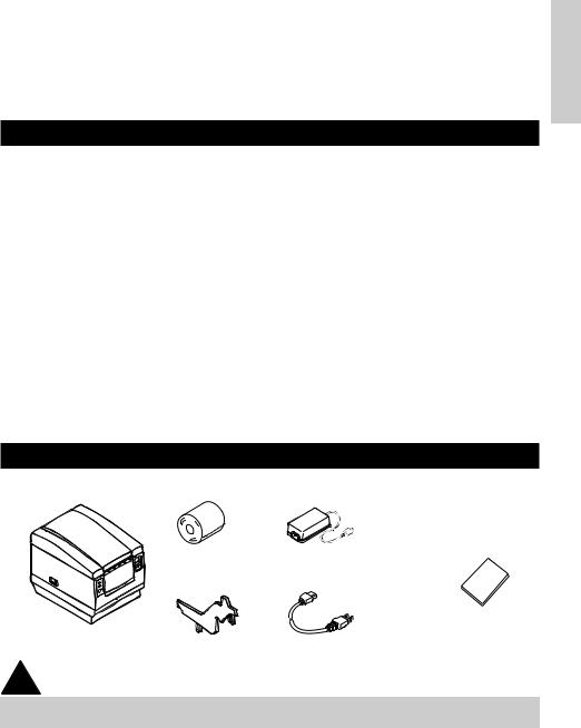
1.2Unpacking
When unpacking the printer, confirm that the following are provided:
ENGLISH
Sample paper roll |
AC adapter |
|
(provided with the A type only) |
Printer |
User’s manual |
Partition |
AC power cord |
|
(not supplied with Type D) |
 CAUTION
•Do not use the printer in an environment where condensation can occur. If condensation forms, leave the power off until it completely evaporates.
—9 —
ENGLISH
2.BASIC SPECIFICATIONS
2.1Model Classification
The printer models are classified by the following designation method:
CBM1000 II R F 120 S - L
Model Name
*Dedicated adapter type and power cord: 31AD-U (AC 120 V 3-wire cord)
31AD-E (AC 230 V Class I cord)
Label paper function no display: Nothing
L: Label interval detection
Power supply S: Standard type
(Power supply built-in) A: AC adapter type
D: Without AC adapter
Attached power cord specification 120: For AC 120 V
230: For AC 230 V
024: Without AC adapter
Character Set
F: International
Interface
R: Serial (RS-232C) P: Parallel
(IEEE 1284 compliant)
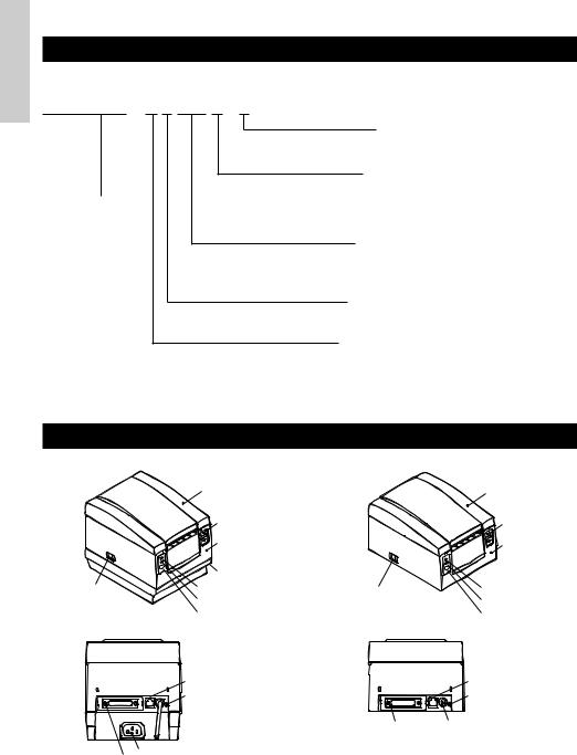
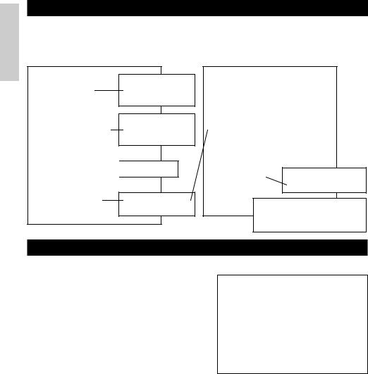
2.2 Outer Appearance and Component Parts
CBM1000II S |
CBM1000II A/CBM1000II D |
||
|
Printer cover |
|
Printer cover |
|
Ejector |
|
Ejector |
|
|
|
|
|
Top cover |
|
Top cover |
|
|
|
|
|
Power box |
|
|
Power switch |
POWER lamp |
Power switch |
POWER lamp |
|
ERROR lamp |
|
ERROR lamp |
|
FEED switch |
|
FEED switch |
|
Drawer kick-out connector |
|
Drawer kick-out |
|
|
connector |
|
|
Grounding terminal |
|
Grounding terminal |
|
|
Interface connector |
Power connector |
|
Inlet |
|
|
|
Interface connector |
|
|
— 10 —
2.3 Basic Specifications
Model |
CBM1000II RF120S/A |
CBM1000II RF230S/A |
CBM1000II RF024D |
|
Item |
CBM1000II PF120S/A |
CBM1000II PF230S/A |
CBM1000II PF024D |
|
|
|
|
||
Print method |
Line thermal dot print method |
|
||
Print width |
72 mm/576 dots, (54 mm/432 dots)*1 |
|
||
Dot density |
8 × 8 dots/mm (203 dpi) |
|
|
|
Print speed |
150 mm/sec (Fastest, print density standard level), (1,200 dot lines/sec) |
|||
Number of print |
Font A: 48/42 (36/30)*1 columns (12 × 24) |
|
||
columns*2 |
Font B: 64/56 (48/40)*1 columns (9 × 24) |
|
||
Character size |
Font A: 1.25 × 3.00 mm; Font B: 0.88 × 3.00 mm |
|
||
Character type code |
Alphanumeric characters, International characters, Code pages PC437, |
|||
page |
Katakana, PC850, PC860, PC863, PC865, PC852, PC866, PC857, and Windows |
|||
|
code page |
|
|
|
Logo registration/print |
Capable of registering user-defined characters and logos into flash memory. |
|||
Types of bar code |
UPC-A/E, JAN (EAN) 13/8 columns, ITF CODE 39, CODE 128, CODABAR, |
|||
|
CODE 93 |
|
|
|
Line spacing |
4.23 mm (1/6 inches), selectable using commands |
|
||
Paper roll |
Thermal paper roll: 80 mm (58 mm) × ø 83 mm |
|
||
|
Thermal Label paper roll : 80 mm (58 mm) × ø 83 mm |
|
||
|
(See “ Print Paper Specifications”.) |
|
||
Label detection |
Selects the L-Spec. (factory option) |
|
||
Interfacing |
Serial (RS-232C), Parallel (IEEE1284 compliant, Bi-directional communication) |
|||
Input buffer |
4K bytes (72 bytes selectable with a DIP switch) |
|
||
Supply voltage |
S type: AC 120/230 V ±10%; A type/D type: DC 24 V ±7% |
|||
Power consumption |
Approx. 100 W |
|
|
|
AC adapter specification |
Rated input: AC 120 to 240 V, 50/60 Hz, 120 VA |
— |
||
|
Rated output: DC 24 V, 1.9 A (Peak 3.5A) |
|||
|
|
|||
Type |
31 AD-U |
|
31 AD-E |
— |
Weight |
S type: Approx. 2.0 Kg; A type/D type: Approx. 1.4 Kg |
|
||
Outside dimensions |
S type: 145 (W) × 190 (D) × 157 (H) mm |
|
||
|
A type/D type: 145 (W) × 190 (D) × 114 (H) mm |
|
||
Operating temperature |
5 to 40°C, 35 to 85% RH (No condensation) |
|
||
and humidity |
|
|
|
|
Storage temperature and |
–20 to 60°C, 10 to 90% RH (No condensation) |
|
||
humidity |
|
|
|
|
Reliability |
Print head life: |
Pulse resistance 1 × 10⁸ pulses (Print ratio 12.5%) |
||
|
|
Wear resistance 100 Km (At normal temperature/humidity |
||
|
|
with recommended paper used) |
|
|
|
Auto cutter life: |
500,000 times of cutting (At normal temperature/humidity |
||
|
|
with recommended paper used) |
|
|
Safety Standard*3 |
UL, C-UL, FCC Class A |
TÜV, GS, CE marking |
UL, C-UL, FCC Class A, |
|
|
|
|
|
TÜV, GS, CE marking |
|
|
|
|
|
*1 Represents the value when a 58 mm wide paper roll is used (User selectable). *2 The number of printable columns is selectable with a DIP switch.
*3 Represents the safety standards acquired when CBM-made adapters (31AD series) are used.
ENGLISH
— 11 —

ENGLISH
2.4Print Paper Specifications and Print Position
(1)Thermal Paper roll
|
Paper width 80 +0/-1 |
|
|
Paper width 58 |
|
4 |
Maximum print area 72 |
4 |
2 |
Maximum print area 54 |
2 |
Unit: mm
|
|
|
Printing surface |
ø83 or less |
ø18 |
ø12 |
60~80 m |
(Recommended papers) TF50KS-E2C from Nippon Paper KP50 from Shin-Ohji Paper F230AA or HP220A from Mitsubishi Paper or equivalent
(2) Thermal label sheet (label gap detection) * Only L-Spec.
Printing surface
Base sheet width: 80 +0/-1 |
Base sheet width: 58 +0/-1 |
|
Max. label width: 76 |
Max. label width: 54 |
|
Maximum print area 72 |
Maximum print area 50 |
|
Minimumlabel gap |
Approx. 2 |
Minimumlabel length |
25 |
||
4 |
2 |
|
|
Approx. |
|
Unit: mm
 CAUTION
ø83 or less |
ø25~28 |
65~85 m |
µm or less |
|
|
|
60 |
(Recommended papers) KPT86S/G63BC P22 from Ohji Tac. or equivalent
•A roll paper not complying with the specifications may cause some departure in print tone. Adjust print tone with the DIP switch (see “Setting DIP Switches”).
•Do not paste paper end to the core as it may cause coloration or faint letters if printed documents are exposed to a particular chemical or oil afterwards.
•Rubbing the document surface with your nail or metallic device may cause coloration.
•Coloration occurs at a temperature of around 70°C or above. Keep documents away from heat, moisture, or light.
— 12 —
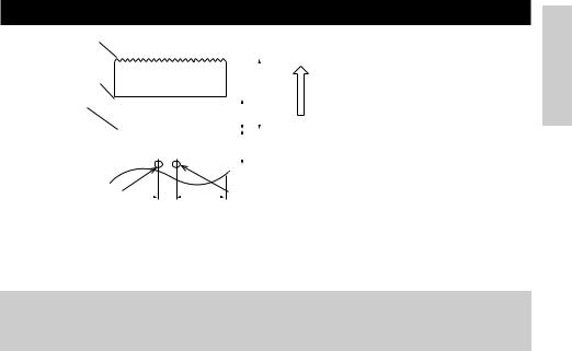
2.5 Sensor Position and Cutter Position
Manual cutting position
Auto cutting position
Top print line
|
|
|
|
|
|
|
|
|
|
feed direction |
|
|
|
|
|
|
|
|
|
|
|
|
|
|
|
|
|
|
|
|
Approx. 27 |
|
|
|
|
|
|
Approx.13 |
|
|
|||
|
|
|
|
|
|
|
|
Paper |
||
|
|
|
|
|
17 |
|
|
|
|
|
|
|
|
|
|
Approx. |
|
|
|
|
|
|
|
|
|
|
|
|
|
|
|
|
|
|
|
|
|
|
|
|
|
|
|
|
|
|
|
|
|
|
|
|
|
|
Paper end sensor |
|
|
|
Label gap sensor |
(11mm) |
|
|||
|
(40mm) |
|||
|
|
|
|
Unit: mm |
 CAUTION
•Observe the following rules on the auto cutter usage:
•Every cut paper should be no less than 10 mm in length. Thin paper strips can cause paper to jam.
•When cutting a label roll, be sure to cut the base sheet. Never cut labels (tags).
ENGLISH
— 13 —
3. OPERATION
ENGLISH |
1 |
Turn off the power of the printer. |
|
3.1 Connecting the AC Adapter and AC Power Cord |
|
|
2 |
For the AC adapter type only: With the flat side of the AC adapter’s cable connector |
|
|
facing upward, insert the cable connector into the power connector on the back side of |
|
|
the printer. |
|
3 |
Connect the AC power cord to the inlet of the printer, and insert the AC power-cord |
|
|
plug into a suitable wall outlet. |
Standard type |
|
|
Inlet |
|
AC power cord |
AC adapter type |
Power connector |
|
|
|
Inlet |
|
Flat side |
|
Cable connector |
|
AC adapter |
|
AC adapter cord |
Power connector pin configuration
No. Function
1+24
2GND
3N.C
SHELL F.G
1 3
2
Connector used: TCS7960-53-2010 (Hosiden) or equivalent
Applicable connector: TCP8927-63-1100 (Hosiden) or equivalent
TCP8927-53-1100 (Hosiden) or equivalent
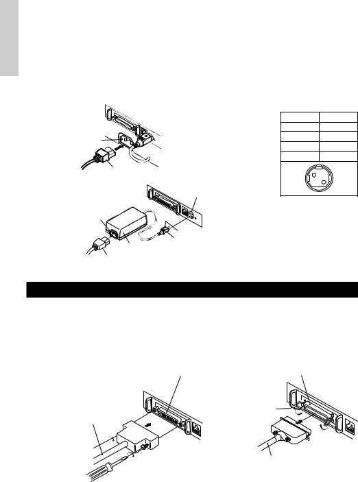
3.2 Connecting Interface Cables
1Turn off the power of the printer. (As well as the connected host computer.)
2Orient the interface cable terminal correctly and insert it into the interface connector.
3Secure the cable terminal as shown below.
Serial interface cable: Fasten the connector with screws. Parallel interface cable: Hold the connector with clamps.
4 Connect the other end of the interface cable to the host computer.
Serial interface connector |
Parallel interface connector |
|
Clamps |
Serial interface cable |
|
Parallel interface cable
— 14 —
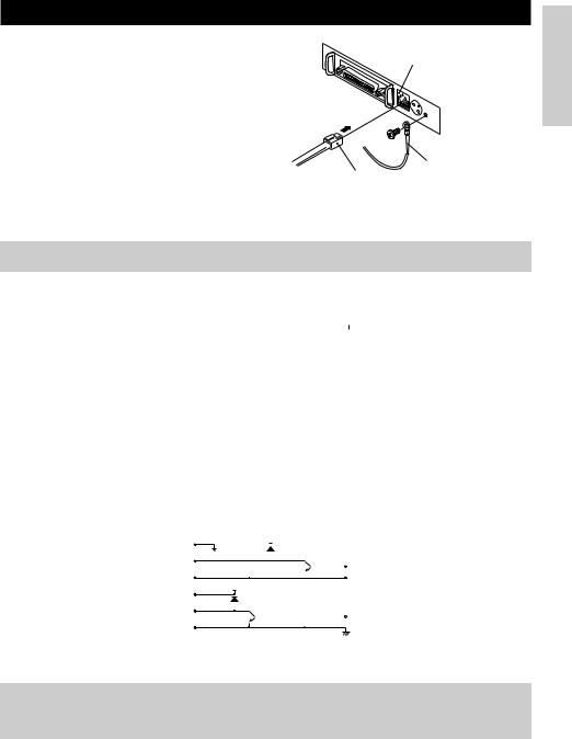
3.3 Connecting the Drawer Kick-Out Connector
1 |
Turn off the power of the printer. |
Drawer kick-out connector |
2 |
Orient the drawer kick-out cable connector |
|
|
correctly, insert it into the drawer kick-out |
|
|
connector on the back of the printer. |
|
3 |
Fasten the ground wire to the ground |
|
|
connector on the printer with a screw. |
|
ENGLISH
Ground wire
Drawer kick-out cable connector
 CAUTION
•Do not connect any other device than the specified drawer (Solenoid) to the drawer kick-out connector. (Do not connect a telephone line either.)
(1) Connector Pin Configuration
|
|
No. |
Signal |
|
Function |
|
|
|
|
|
|
|
|
|
|
|
|
|
|
|
Connector used: |
|||||
|
|
|
|
|
|
|
|
|
|
|
|
|
|
|
|
|
|
TM5RJ3-66 (Hirose) or |
||||||||
|
|
1 |
FG |
Frame Ground |
|
|
|
|
|
|
|
|
|
|
|
|
|
|
|
equivalent |
||||||
|
|
2 |
DRAWER 1 |
Drawer 1 drive signal |
|
|
|
|
|
|
|
|
|
|
|
|
|
|
|
Applicable connector: |
||||||
|
|
3 |
DRSW |
Drawer switch input |
|
|
|
|
|
|
|
|
|
|
|
|
|
|
|
|||||||
|
|
|
|
|
|
|
|
|
|
|
|
|
|
|
|
|
TM3P-66P (Hirose) or |
|||||||||
|
|
4 |
VDR |
Drawer drive power supply |
|
|
|
|
|
|
|
|
|
|
|
|
|
|
|
|||||||
|
|
|
|
|
|
|
|
|
|
|
|
|
|
|
|
|
equivalent |
|||||||||
|
|
5 |
DRAWER 2 |
Drawer 2 drive signal |
|
|
|
|
|
|
|
|
|
|
|
|
|
|
|
|
||||||
|
|
|
|
|
|
|
|
|
|
|
|
|
|
|||||||||||||
|
6 |
|
1 |
|
|
|
|
|||||||||||||||||||
|
|
6 |
GND |
Common ground on circuits |
|
|
|
|
|
|
|
|
||||||||||||||
|
|
|
|
|
|
|
|
|
|
|
|
|
|
|
|
|
|
|||||||||
(2) |
Electrical characteristics |
|
|
|
|
|
|
|
|
|
|
|
|
|
||||||||||||
|
1) Driving voltage: 24 VDC |
|
|
|
|
|
|
|
|
|
|
|
|
|
||||||||||||
|
2) Driving current: Approx. 1 A max. (shall not exceed 510 ms.) |
|||||||||||||||||||||||||
|
3) DRSW signal: Signal levels: “L”=0 to 0.5 V, “H”=3 to 5 V |
|||||||||||||||||||||||||
(3) DRSW signal |
|
|
|
|
|
|
|
|
|
|
|
|
|
|
|
|
|
|
|
|
|
|
|
|||
|
DRSW signal status can be tested with the DLE+EOT, GS+a, or GS+r command or at pin 34 |
|||||||||||||||||||||||||
|
on the parallel interface port. |
|
|
|
|
|
|
|
|
|
|
|
|
|
||||||||||||
(4) |
Drive Circuit |
|
|
|
|
|
|
|
|
|
|
|
|
|
|
|
|
|
|
|
|
|
|
|
||
|
|
|
|
1 |
|
|
|
|
VDR |
|
|
|
|
|
|
|
|
|
|
|
|
|
||||
|
|
|
|
|
|
|
|
|
|
|
|
|
|
|
|
|
|
|
|
|
|
|
|
|
|
|
|
|
|
|
|
|
|
|
|
|
|
|
|
|
|
|
|
|
|
|
|
|
|
|
|
|
|
|
|
|
|
2 |
|
|
|
|
|
|
|
|
|
|
|
|
|
|
|
|
|
|
|
|
|
|
|
|
|
|
|
|
|
|
|
|
|
|
|
|
|
|
|
|
|
|
|
|
|
|
|
|
|
|
|
|
|
3 |
|
VDR |
|
|
|
|
|
|
|
|
|
|
|
|
|
|
|
|||||
|
|
|
|
|
|
|
|
|
|
|
|
|
|
|
|
|
|
|
||||||||
|
|
|
|
4 |
|
|
|
|
|
|
|
|
|
|
|
|
|
|
|
|
||||||
|
|
|
|
|
|
|
|
|
|
|
|
|
|
|
|
|
|
|
|
|
|
|
|
|
|
|
|
|
|
|
|
|
|
|
|
|
|
|
|
|
|
|
|
|
|
|
|
|
|
|
|||
|
|
|
|
5 |
|
|
|
|
|
|
|
|
|
|
|
|
|
|
|
|
|
|
|
|
|
|
|
|
|
|
|
|
|
|
|
|
|
|
|
|
|
|
|
|
|
|
|
|
|
|
|||
|
|
|
|
6 |
|
|
|
|
|
|
|
|
|
|
|
|
|
|
|
|
|
|
|
|
|
|
|
|
|
|
|
|
|
|
|
|
|
|
|
|
|
|
|
|
|
|
|||||||
 CAUTION
•No output is produced while printing.
•The drawers 1 and 2 cannot be driven simultaneously.
•A solenoid used for the drawer should be of 24 Ω or more. The output current should be kept at 1 A or less; otherwise, breakdown or burning could occur.
—15 —
ENGLISH
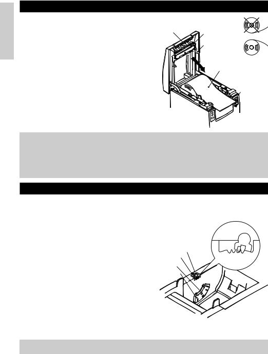
3.4 Setting/Replacing Paper Rolls
1 |
Turn on the printer. |
|
2 |
Push the ejector in the direction shown to |
Tear bar |
|
unlock the printer cover. |
|
|
|
|
3 |
Placing your hands on both sides of the |
|
|
printer cover, open it until it comes to a |
|
|
stop. |
|
4 |
Check the winding direction of the paper |
|
|
roll, and then place it into the paper roll |
|
|
holder correctly. |
|
5 |
With the end of the paper approx. 5 cm out |
|
|
of the case of the printer, close the printer |
|
|
cover. Push lightly on the printer cover |
|
|
until a “click” is heard. |
|
6 |
Remove an excess length of paper with |
|
|
the tear bar. (Manual cutter) |
|
Print head
Printer cover
Paper roll
Ejector
 CAUTION
•Always use the specified types of paper roll.
•Use of other types of paper roll may not be able to guarantee the specified print quality or service life of the printer.
•When opening the printer cover, do not apply an excess force to it beyond its stop position.
•The print head becomes hot immediately after printing. Do not touch it with your hand. During printing, do not open the printer cover. Do not hold the end of the paper as it prints and ejects. Doing so may cause the paper to jam.
3.5 Adjusting the Paper Near-End Sensor
1Open the printer cover.
2Push the sensor knob in the direction of arrow 1 to disengage its claw (Or unlock the sensor unit), and then adjust the sensor unit to a desired paper remaining position within the range shown by arrow 2.
3The following table shows the relationship between adjustment positions and levels of paper roll remaining. (A rough guide)
Adjustment |
Level of paper remaining |
position |
(Paper roll outside diameter/mm) |
1 |
ø18 |
2 |
ø21 |
3 |
ø24 |
4 |
ø27 |
* When specified paper rolls are used.
Sensor knob Arrow 1
Arrow 2
Sensor unit
4 3 2 1
Adjustment position
 CAUTION
•Use the level of paper remaining (Paper-roll outside diameter) just as a guide as it varies depending on the particular printer and paper rolls used.
—16 —
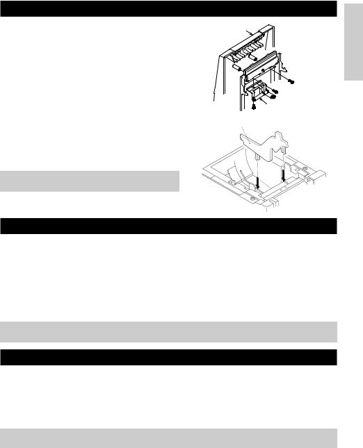
3.6 Using 58 mm Wide Paper Rolls
1Turn off the power of the printer.
2Open the printer cover.
3Take off two screws and remove printer cover.
4Take off damper retention screws, reposition damper (11 mm) in the direction of the arrow, then secure it with the original screws again.
5Replace printer cover on printer.
6Install the supplied partition into the position as illustrated.
7Change DIP switch setting for 58 mm roll paper, by referring to “SETTING DIP SWITCHES”.
 CAUTION
•Do not change DIP switch setting from 58 mm into 80 mm roll paper in the middle of printing.
Printer cover
Damper
Partition
3.7 Removing Jammed Paper
1Turn off the power of the printer.
2Open the printer cover.
3Remove the paper jam including any paper chips remaining. (Also take out the paper roll from the holder.)
4Close the printer cover.
5Turn on the printer. The auto cutter mechanism is initialized and the alarm is cleared.
 CAUTION
•The print head becomes hot immediately after printing. Do not touch it with your hand. Do not touch the heating element of the head with a bare hand or metal object either.
3.8 Cleaning the Print Head
1Open the printer cover.
2Wipe off stains, such as dust and the like, on the heating element of the head using a cotton swab soaked in ethyl alcohol.
 CAUTION
•The print head becomes hot immediately after printing. Do not touch it with your hand. Do not touch the heating element of the head with a bare hand or metal object either.
—17 —
ENGLISH
ENGLISH
3.9 Operation Panel and Error Indication
1POWER lamp (Green)
Lights when the power is turned on. It blinks when a memory check error has occurred.
2ERROR lamp (Red)
Lights or blinks to show different error states. It also blinks while the printer is waiting for a macro to be executed.
3FEED switch
Pressing this switch briefly causes one line of paper feeding.
While a macro is waiting to be executed, pressing the switch causes the macro to be executed.
4Buzzer
A buzzer sound alerts the operator to an error.
POWER lamp (Green)
POWER
ERROR lamp (Red)
ERROR
FEED switch
FEED
Error indication |
POWER lamp |
|
|
ERROR lamp |
|
|
|
Buzzer |
Recovery method |
||||||||
|
|
|
|
|
|
|
|
|
|
|
|
|
|
|
|
|
|
Memory Check |
Quick blinking |
|
|
Lights |
|
|
|
|
— |
Not recoverable |
|||||||
error |
|
|
|
|
|
|
|||||||||||
|
|
|
|
|
|
|
|
|
|
|
|
|
|
|
|
|
|
|
|
|
|
|
|
|
|
|
|
|
|
|
|
|
|
|
|
Cover open |
Lights |
|
|
Lights |
(Four short beeps) × 2 |
Close the cover. |
|||||||||||
|
|
|
|
|
|
|
|
|
|||||||||
|
|
|
|
|
|
|
|
|
|
|
|
|
|
|
|
|
|
Head overheat |
Lights |
|
|
|
|
|
|
|
|
|
|
— |
Recovers automatically |
||||
|
Slow blinking |
|
|
|
|
when the temperature |
|||||||||||
|
|
|
|
|
|
|
|
|
|
|
|
returns to normal. |
|||||
|
|
|
|
|
|
|
|
|
|
|
|
|
|
|
|
|
|
Paper near-end |
Lights |
|
|
Lights |
|
|
|
|
— |
Set a new paper |
|||||||
|
|
|
|
|
|
roll. |
|||||||||||
|
|
|
|
|
|
|
|
|
|
|
|
|
|
|
|
|
|
|
|
|
|
|
|
|
|
|
|
|
|
|
|
|
|
|
|
Paper end |
Lights |
|
|
Lights |
|
|
|
|
|
|
|
|
|
Set a new paper |
|||
|
|
(Four short beeps) × 2 |
roll. |
||||||||||||||
|
|
|
|
|
|
|
|
||||||||||
|
|
|
|
|
|
|
|
|
|
|
|
|
|
|
|
|
|
Cutter motor lock |
Lights |
|
|
|
|
|
|
|
|
|
|
|
|
|
|
|
Remove paper |
|
|
|
|
|
|
|
|
|
|
|
|
|
|
|
|||
|
|
|
|
|
|
|
|
|
|
|
|
|
|
|
|||
Quick and slow blinking |
|
Three long beeps |
jams. |
||||||||||||||
|
|
|
|||||||||||||||
|
|
|
|
||||||||||||||
|
|
|
|
|
|
|
|
|
|
|
|
|
|
|
|
|
|
Macro execution |
Lights |
|
|
|
|
|
|
|
|
|
|
— |
Press the FEED |
||||
wait |
|
Slow blinking |
|
|
|
|
switch. |
||||||||||
|
|
|
|
|
|
|
|
|
|
|
|||||||
|
|
|
|
|
|
|
|
|
|
|
|
|
|||||
|
|
|
|
|
|
|
|
|
|
|
|
|
|
|
|
|
|
Low voltage error |
Lights |
|
|
Lights |
|
|
|
|
— |
Not recoverable |
|||||||
|
|
|
|
|
|
|
|
|
|
|
|
|
|
|
|
|
|
High voltage error |
Lights |
Quick and slow blinking |
|
|
|
|
— |
Not recoverable |
|||||||||
|
|
|
|
|
|
|
|
|
|
|
|
||||||
|
|
|
|
|
|
|
|
|
|
|
|
|
|
|
|
|
|
Waiting for label |
Off |
|
|
|
|
|
|
|
|
|
|
— |
Press the FEED |
||||
cutter action |
|
|
|
|
|
|
|
|
|
|
switch. |
||||||
|
|
|
|
|
|
|
|
|
|
|
|
|
|
|
|
||
|
|
|
|
|
|
|
|
|
|
|
|
|
|
|
|
|
|
Waiting for label |
Off |
|
|
|
|
|
|
|
|
|
|
— |
Remove label from |
||||
|
|
|
|
|
|
|
|
|
|
||||||||
discharge |
|
Slow blinking |
|
|
|
|
peeler. |
||||||||||
|
|
|
|
|
|
|
|
|
|
|
|||||||
|
|
|
|
|
|
|
|
|
|
|
|
|
|||||
|
|
|
|
|
|
|
|
|
|
|
|
|
|
|
|
|
|
Label detection |
Off |
|
|
|
|
|
|
|
|
|
|
|
|
|
|
|
Set the specified |
error |
|
Slow blinking |
|
Three long beeps |
label roll. |
||||||||||||
|
|
|
|||||||||||||||
|
|
|
|
|
|||||||||||||
|
|
|
|
|
|
|
|
|
|
|
|
|
|
|
|
|
|
— 18 —

Description of errors
Memory Check error:
This error occurs if a memory read-after-write check or FROM sum check has resulted in an error (unrecoverable error).
Cover open:
When you open the printer cover, the cover open sensor is activated, causing the ERROR lamp to light and the printing operation to stop. (Not recoverable error)
Head overheat:
To protect the print head from overheating, the head temperature sensor is activated if the head temperature rises over approx. 65°C, causing the ERROR lamp to blink and the printing operation to stop. Printing resumes automatically when the head temperature lowers below approx. 60°C. (Auto recoverable error)
Paper near-end:
As the paper roll diameter becomes small, the Paper near-end sensor is activated and causes the ERROR lamp to light, indicating the paper supply has become low. (See “Selecting the paper sensor valid for paper end signal output” and “Selecting the Paper Near-End Sensor valid for print stop”.)
Paper end:
When the paper roll has run out, the Paper end-sensor located near the print head on the paper path detects the end of the paper roll, causing the ERROR lamp to light and printing to stop. (See “Selecting the paper sensor valid for paper end signal output” and “Selecting the Paper Near-End Sensor valid for print stop”.)
Cutter motor lock:
While the cutter motor is running, if the cutter position detecting sensor inside the cutter unit remains ON or OFF for approx. 1 second or more, the printer determines that the motor has locked, causing the cutter operation and printing to stop. (See “Removing Jammed Paper”.)
Low voltage error:
Occurs when the voltage supplied to the printer decreases ; if this has occurred, turn the power off immediately. (Not recoverable error)
High voltage error:
Occurs when the voltage supplied to the printer increases ; if this has occurred, turn the power off immediately. (Not recoverable error)
Waiting for label cutter action:
Wait until the label discharged by the GS+FF (Cut Label and Discharge) command is cut by the manual cutter and the FEED switch is pressed. If “No Cutter” or “No Peeling Mechanism” is selected, the printer becomes Busy.
Waiting for Label Discharge:
Waiting for a label to be removed from the base sheet after it was discharged by the GS+FF (Cut Label & Eject) command (if the peeler is selected). The printer becomes Busy.
Label detection error:
Label gaps or black marks could not be detected, or the label sheets used do not fall in the specified length limits.
If a label detection error occurs even though the label sheets used fall in the specified length limits, it is most likely that the sensor or its peripheral electronics is defective. The printer becomes Busy.
ENGLISH
— 19 —
ENGLISH
3.10 Self-printing
When the power is turned on while the FEED switch is pressed, the printer will perform preset printing. After the self-printing is completed, the printer will return to the normal operation conditions.
C B M 1 0 0 0
M P V 3 . x x
L P V 3 . x x
Serial Interface
Baud Rate : 19200 bps
Data Bit : 8 bits
Parity : None
Handshake : DTR/DSR
Buffer Size |
|
|
|
|
|
4K bytes |
|
|
|
|
|
Dip Switches |
|
|
|
|
|
|
DS1 |
|
|
|
|
|
1 2 3 4 5 6 7 |
8 |
|
||
ON |
o |
o |
|
|
|
OFF |
o o o o o |
|
|
o |
|
Program & loader versions
Interface and its status (serial I/F in this example)
Buffer size
DIP switch status (DS3 for serial only)
|
DS2 |
|
1 2 3 4 5 6 7 8 9 10 |
ON |
o |
OFF |
o o o o o o o o o |
|
DS3 |
|
1 2 3 4 5 6 7 8 |
ON |
o |
OFF o o o o o o o
! ” # $%& ’ ( ) * + , – . / 0 1 2 3 4 5 6 7 8 9 : ; < =>?@ABC
DEFGH I JKLMNOPQRSTUVWXYZ [ \ ] ^ _ ` a bc d e f g H i j k l mno pq r s t u vwx y z { | } ~ . . . . . . . .
•
•
•All the printable characters are printed.
If the Auto Cutter is used, the paper is cut into pages each time a page is printed.
3.11 Hexadecimal Dump
1Hexadecimal dump function allows data sent from the host computer to be printed in hexadecimal numbers as well as in characters corresponding to the numbers.
2Starting hexadecimal dump
To start hex dump, turn the printer On while pressing and holding the FEED switch, with the printer cover left open. When you close the printer cover, the printer first prints “Hexadecimal Dump”, then prints all the subsequent data in hex and characters.
NOTE
<Example of hexadecimal dump>
=== Hexadecimal Dump === |
|
|
||||||
To terminate hexadecimal dump, |
|
|||||||
Press FEED switch three times. |
|
|||||||
1B 40 73 |
6D 70 |
6C 65 |
0A |
30 |
31 |
32 |
.@s amp l e . 0 1 |
|
33 34 35 36 37 |
38 39 |
41 |
42 |
43 |
44 |
3456789ABCD |
||
45 46 47 |
48 49 |
4A |
4B |
4C |
4D 4F |
50 |
EFGHI JKLMOP |
|
51 52 53 |
54 55 |
56 57 58 |
59 |
5A |
0D |
QRSTUVWXYZ . |
||
61 62 63 |
64 65 |
66 67 68 |
69 |
6A |
6B |
a bcd e f gh i j k |
||
6C 6D 6E 6F 70 71 |
72 |
73 74 75 76 |
l mnopq r s t u v |
|||||
77 78 79 |
7A 0D |
0A |
0A |
0A |
|
|
|
wxy z . . . . |
=== Completed ===
•If a character is not available corresponding to the data received, “ . ” is printed instead.
•During hexadecimal dump, no other functions than DLE EOT and DLE ENQ work.
•If the data received is not enough for a full line, pressing the FEED switch causes the line to be printed.
3Quitting hexadecimal dump
The printer exits Hex Dump mode when it is turned off, the FEED switch is pressed 3 times consecutively, or the printer receives a Reset signal from the interface, after hex dump is completed.
—20 —

3.12Printer Buffer
3.12.1Buffering
The printer buffer has a capacity of 4K bytes (DS1-6: OFF). The host is released immediately after it transfers data to the printer.
3.12.2 Buffer Full Busy
If the printer buffer becomes full, the Busy/DTR signal is set to “High” to indicate “Buffer Full” to the host. The printer is unable to receive data from the host while in Buffer Full.
Printer Buffer |
Busy/DTR Asserted |
Busy/DTR Reset |
|
|
|
4K bytes |
128 bytes remaining |
256 bytes remaining |
|
|
|
72 bytes |
20 bytes remaining |
30 bytes remaining |
|
|
|
Note: The printer buffer can be initialized with DS1-6.
3.13 Device ID
On receiving a Device ID request from the host, the printer returns a device ID as shown below through the parallel interface:
<00>H<31>H
MFG:CBM;
CMD:CBM;ESC/POS;
MDL:CBM1000;
CLS:PRINTER;
The first 2 bytes of the device ID indicates the total length of the ID including itself.
ENGLISH
— 21 —
ENGLISH
4.SETTING DIP SWITCHES
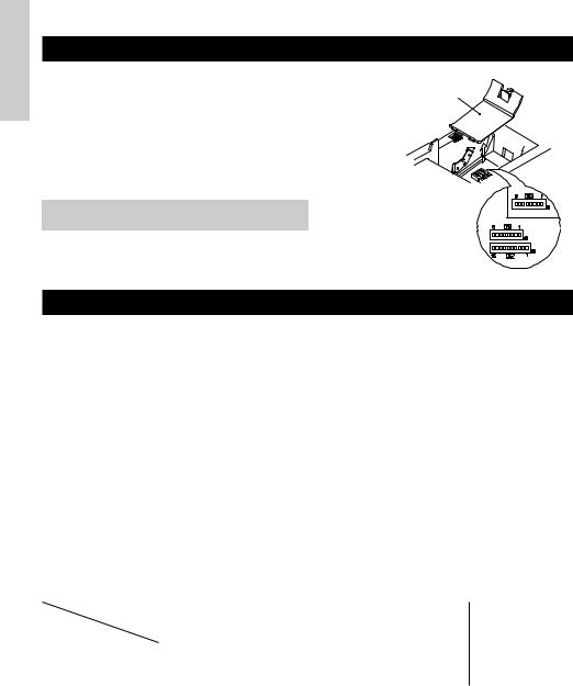
4.1Location of DIP Switches
1Turn off the power of the printer.
2Open the printer cover.
3Remove the paper roll and the DIP switch cover.
4After completing the setting, place the cover to the original position.
 CAUTION
•Do not make settings while the printer is turned on.
DIP switch cover
*DIP switch 3 is only for the serial interface.
4.2Table for Setting DIP Switches
4.2.1DIP switch 1
No. |
Function |
|
ON |
OFF |
Factory presetting |
|
|
|
|
|
|
1-1 |
Auto cutter |
|
Available |
Not available |
ON |
|
|
|
|
|
|
1-2 |
Unused |
|
- |
- |
OFF |
|
|
|
|
|
|
1-3 |
Paper width |
|
58 mm |
80 mm |
OFF |
|
|
|
|
|
|
1-4 |
Print columns* |
|
42 columns (80 mm) |
48 columns (80 mm) |
OFF |
|
30 columns (58 mm) |
36 columns (58 mm) |
|||
|
|
|
|
||
|
|
|
|
|
|
1-5 |
CR mode |
|
LF operation |
Ignored |
OFF |
|
|
|
|
|
|
1-6 |
Input buffer |
|
72 bytes |
4K bytes |
OFF |
|
|
|
|
|
|
1-7 |
|
Print density (See the tabel below.) |
ON |
||
|
|
|
|||
1-8 |
|
|
|
|
OFF |
|
|
|
|
|
|
* It will be different according to the setting of paper width (DS1 – 3).
Print density
Print density |
Level 1 |
Level 2 |
Level 3 |
Level 4 |
No. |
(Light) |
(Standard) |
(Slightly dark) |
(Dark) |
|
|
|
|
|
|
|
|
|
|
1-7 |
OFF |
ON |
OFF |
ON |
|
|
|
|
|
1-8 |
OFF |
OFF |
ON |
ON |
|
|
|
|
|
Note: If print density is set to level 2 (Standard) or over, print speed may decrease.
— 22 —

4.2.2 DIP switch 2
No. |
Function |
ON |
OFF |
Factory presetting |
ENGLISH |
|
|
|
|
|
|
2-1 |
|
|
|
OFF* |
|
|
|
|
|
||
|
|
|
|
|
|
2-2 |
|
|
|
|
|
Character code (See the table below.) |
OFF* |
|
|||
|
|
|
|||
2-3 |
|
|
|
OFF* |
|
|
|
|
|
|
|
2-4 |
|
|
|
OFF* |
|
|
|
|
|
|
|
2-5 |
Unused |
– |
– |
OFF |
|
|
|
|
|
|
|
2-6 |
Condition for BUSY to |
Reception buffer full |
Off-line and reception |
OFF |
|
occur |
buffer full |
|
|||
|
|
|
|
||
|
|
|
|
|
|
2-7 |
Paper |
Thermal label paper |
Thermal paper |
OFF |
|
|
|
|
|
|
|
2-8 |
Detection |
Black mark |
Label interval |
OFF |
|
|
|
|
|
|
|
2-9 |
Label length set |
Command |
Auto |
OFF |
|
|
|
|
|
|
|
2-10 |
Label Peeler |
Available |
Not available |
OFF |
|
|
|
|
|
|
|
* Depends on destinations.
4.2.3 DIP switch 3
No. |
Function |
ON |
|
OFF |
Factory presetting |
|
|
|
|
|
|
3-1 |
Bit length |
7 bits |
|
8 bits |
OFF |
|
|
|
|
|
|
3-2 |
Parity |
Available |
|
Not available |
OFF |
|
|
|
|
|
|
3-3 |
Odd/even |
Even number |
|
Odd number |
OFF |
|
|
|
|
|
|
3-4 |
Communication mode |
XON/XOFF |
|
DTR/DSR |
OFF |
|
|
|
|
|
|
3-5 |
Baud rate (See the table below.) |
|
OFF |
||
|
|
|
|||
3-6 |
|
ON |
|||
|
|
|
|
||
|
|
|
|
|
|
3-7 |
DSR |
Reset |
|
DSR |
OFF |
|
|
|
|
|
|
3-8 |
INIT |
Reset |
|
— |
OFF |
|
|
|
|
|
|
* DIP switch 3 is only for the serial interface.
Selection of character code tables |
|
|
|
|
Baud rate |
|
|
||
|
|
|
|
|
|
|
|
|
|
|
No. |
2-1 |
2-2 |
2-3 |
2-4 |
|
No. |
3-5 |
3-6 |
Code |
|
|
|
|
|
Baud rate |
|
|
|
Code 437 (USA: Standard Europe) |
OFF |
OFF |
OFF |
OFF |
|
4,800 bps |
OFF |
OFF |
|
Katakana (Japanese) |
ON |
OFF |
OFF |
OFF |
|
9,600 bps |
ON |
OFF |
|
Code 850 (Multilingual) |
OFF |
ON |
OFF |
OFF |
|
19,200 bps |
OFF |
ON |
|
Code 860 (Portuguese) |
ON |
ON |
OFF |
OFF |
|
38,400 bps |
ON |
ON |
|
Code 863 (Canadian-French) |
OFF |
OFF |
ON |
OFF |
|
|
|
|
|
Code 865 |
(Nordic) |
ON |
OFF |
ON |
OFF |
|
|
|
|
Code 852 |
(Eastern Europe) |
OFF |
ON |
ON |
OFF |
• “Blank page” is an area for user |
|||
Code 866 |
(Russian) |
ON |
ON |
ON |
OFF |
registration, and is blank (space) |
|||
Code 857 |
(Turkish) |
OFF |
OFF |
OFF |
ON |
by default. |
|
|
|
Windows Code 1252 |
ON |
OFF |
OFF |
ON |
• When “Katakana” is selected, the |
||||
Not defined |
– |
– |
– |
– |
international character is set for |
||||
Blank page |
ON |
ON |
ON |
ON |
Japanese. When the others are |
||||
|
|
|
|
|
|
selected, it is set for USA. |
|
||
— 23 —

ENGLISH
5. MAINTENANCE AND SERVICE
For the information on maintenance and service, please contact your CBM dealer or at the following addresses:
Northern America |
Other Areas |
||
CBM America Corporation |
Japan CBM Corporation |
||
Service Center |
Information Systems Division |
||
363 Van Ness Way |
CBM Bldg. 5-68-10, Nakano |
||
Suite 404 |
|
Nakano-ku, Tokyo 164-0001, Japan |
|
Torrance, CA 90501, U.S.A |
TEL: |
+81-3-5345-7540 |
|
TEL: |
+1-310-781-1460 |
FAX: |
+81-3-5345-7541 |
FAX: |
+1-310-781-9157 |
E-mail: info-sys@jcbm.co.jp |
|
E-mail: |
sales@cbma.com |
http://www.jcbm.co.jp |
|
http://www.cbma.com
 CAUTION
•If the printer has a fatal error, emission of smoke, fire, or other problem, immediately abort the current print session and unplug the printer from the supply outlet. Then call the contacts listed above or your local CBM dealer.
•Never attempt to disassemble or repair the printer by yourself.
— 24 —

FRANÇAIS
FRANÇAIS
— 1 —

FRANÇAIS
TABLE DES MATIÈRES |
|
|
1. PRÉSENTATION GÉNÉRALE ............................................................... |
9 |
|
1.1 |
Caractéristiques ........................................................................................ |
9 |
1.2 |
Déballage ................................................................................................... |
9 |
2. SPÉCIFICATIONS DE BASE ............................................................... |
10 |
|
2.1 |
Classification des modèles .................................................................... |
10 |
2.2 |
Apparence extérieure et nomenclature ................................................ |
10 |
2.3 |
Spécifications de base............................................................................ |
11 |
2.4 |
Spécifications du papier et position d’impression .............................. |
12 |
2.5 |
Position du capteur et position du massicot ........................................ |
13 |
3. FONCTIONNEMENT........................................................................... |
14 |
|
3.1 |
Branchement de l’adaptateur secteur et du cordon d’alimentation .. |
14 |
3.2 |
Branchement des câbles d’interface ..................................................... |
14 |
3.3 |
Branchement du connecteur de renvoi du tiroir ................................. |
15 |
3.4 |
Mise en place/Remplacement des rouleaux de papier ....................... |
16 |
3.5 |
Réglage du capteur de fin de papier proche ........................................ |
16 |
3.6 |
Utilisation de rouleaux de papier de 58 mm de largeur ..................... |
17 |
3.7 |
Retrait du papier coincé ......................................................................... |
17 |
3.8 |
Nettoyage de la tête d’impression ........................................................ |
17 |
3.9 |
Panneau de commande et indication des erreurs ............................... |
18 |
3.10 Impression automatique ...................................................................... |
20 |
|
3.11 Vidage hexadécimal ............................................................................. |
20 |
|
3.12 Tampon de l’imprimante ...................................................................... |
21 |
|
3.13 Identification de périphérique ............................................................. |
21 |
|
4. RÉGLAGES DES COMMUTATEURS À POSITIONS MULTIPLES .... |
22 |
|
4.1 |
Emplacement des commutateurs à positions multiples..................... |
22 |
4.2 |
Tableau pour le réglage des commutateurs à positions multiples .... |
22 |
5. ENTRETIEN ET SERVICE APRÈS-VENTE ......................................... |
24 |
|
APPENDIX 1. OUTLINE DRAWING .......................................................... |
i |
|
APPENDIX 2. BLOCK DIAGRAM .............................................................. |
i |
|
APPENDIX 3. IDENTIFICATION OF SEND STATUS ............................... |
ii |
|
APPENDIX 4. PARALLEL INTERFACE .................................................... |
iii |
|
APPENDIX 5. SERIAL INTERFACE .......................................................... |
v |
|
APPENDIX 6. CONTROL COMMAND ................................................... |
vii |
|
— 2 —
|
PRÉCAUTIONS GÉNÉRALES |
|
1 |
Les informations contenues dans ce mode d’emploi sont susceptibles d’être |
|
|
modifiées sans préavis. |
|
2 |
Tous droits réservés. La reproduction en totalité ou en partie de ce |
|
|
document sans autorisation écrite de CBM Corporation est interdite. |
|
3 |
Sauf en cas d’explication dans ce mode d’emploi, ne tentez pas d’entretenir, |
|
|
de démonter ou de réparer vous-même cet appareil. |
|
|
|
|
4 |
Notez que CBM ne sera pas tenue responsable pour les dommages |
|
|
attribuables à un fonctionnement ou une manipulation incorrecte, ou à des |
FRANÇAIS |
|
environnements de fonctionnement inappropriés qui ne sont pas spécifiés |
|
|
|
|
|
dans ce mode d’emploi. |
|
5 |
Faites fonctionner cette imprimante uniquement de la manière décrite dans |
|
|
ce mode d’emploi afin d’éviter les accidents ou les problèmes. |
|
6 |
Les données sont en principe réservées à une utilisation provisoire, et ne |
|
|
sont pas conservées pendant longtemps ou en permanence. Veuillez noter |
|
|
que CBM ne sera pas tenue responsable en cas de dommage ou de perte de |
|
|
profits résultant de la perte des données provoquée par des accidents, des |
|
|
réparations, des tests, ou toute autre occurrence. |
|
7 |
Si vous avez des questions ou des commentaires concernant les |
|
|
informations contenues dans ce mode d’emploi, veuillez contacter votre |
|
|
revendeur CBM. |
|
8 |
Veuillez noter que CBM ne sera pas tenue responsable pour tout événement |
|
|
se produisant en faisant fonctionner l’imprimante, malgré les indications du |
|
|
paragraphe «7» ci-dessus. |
|
— 3 —
Loading...