


 Loading...

Declaration of Conformity
Manufacturer’s Name |
: Japan CBM Corporation |
Manufacturer’s Address : CBM Bldg., 5-68-10, Nakano, Nakano-ku |
|
|
Tokyo, 164-0001, Japan |
Declare the Product |
|
Product Name |
Line Thermal Printer |
Model Number(s) |
CBM1000 Series |
|
(CBM1000RF/PF) |
|
(S.No.9990001 - ) |
Conform to the following Standards
LVD |
: EN60950 |
EMC |
: EN55022 |
|
: EN61000-3-2 |
: EN61000-3-3 : EN55024
: EN61000-4-2 : EN61000-4-3 : EN61000-4-4 : EN61000-4-5 : EN61000-4-6 : EN61000-4-8 : EN61000-4-11
:A11: 1997
:1998 Class A
:1995
:1995
:1998
:1995 ±4KV CD, ±8 KV AD
:1995 3 V/m, 80 MHz-1000 MHz AM 1 KHz 80 %
:1995 ±1.0 KV(AC Mains), ±0.5 KV(Signal Lines)
:1995 1 KV Normal mode, 2 KV Common mode
:1996 3 V, 0.15 MHz-80 MHz AM 1 KHz 80 %
:1993 50 Hz, 3 A/m(Out of scope)
:1994 10ms/95%, 500ms/30%, 5000ms/100%
Supplementary Information
“The product complies with the requirements of the Low Voltage Directive 73/ 23/EEC, 93/68/EEC and the EMC Directive 89/336/EEC, 92/31/EEC, 93/68/EEC”
Place |
Tokyo, Japan |
Signature |
|
Date |
August 1999 |
|
|
Full Name : Mikio Moriya |
|||
|
|
||
|
|
Position : General Manager |
|
|
|
R & D Department |
European Contact :
Norco Declaration AB
Box 7146 S-250 07 Helsingborg Sweden
Warning : This is a Class A product. In a domestic environment this product may cause radio interference in which case the user may be required to take adequate measures. This declaration is applied only for 230 V model.
— i —

IMPORTANT SAFETY INSTRUCTIONS
•Read all of these instructions and save them for future reference.
•Follow all warnings and instructions marked on the product.
•Unplug this product from the wall outlet before cleaning. Do not use liquid or aerosol cleaners. Use a damp cloth for cleaning.
•Do not use this product near water.
•Do not place this product on an unstable cart, stand or table. The product may fall, causing serious damage to the product.
•Slots and openings on the back or bottom of the case are provided for ventilation. To ensure reliable operation of the product and to protect it from overheating, do not block or cover these openings. The openings should never be blocked by placing the product on a bed, sofa, rug or other similar surface. This product should never be placed near or over a radiator or heater. This product should not be placed in an builtin installation unless proper ventilation is provided.
•This product should be operated from the type of power source indicated on the marking label. If you are not sure of the type of power available, consult your CBM dealer or local power company.
•Do not allow anything to rest on the power cord. Do not place this product where the cord will be walked on.
•If an extension cord is used with this product, make sure that the total of the ampere ratings of the products plugged into the extension cord does not exceed the extension cord ampere rating. Also, make sure that the total of all products plugged into the wall outlet does not exceed 15 amperes.
•Never push objects of any kind into this product through cabinet slots as they may touch dangerous voltage points or short out parts that could result in a risk of fire or electric shock. Never spill liquid of any kind on the product.
•Except as explained elsewhere in this manual, do not attempt to service this product by yourself. Opening and removing the covers that are marked “Do Not Remove” may expose you to dangerous voltage points or other risks. Refer all servicing on those components to service personnel.
•Unplug this product from the wall outlet and refer servicing to qualified service personnel under the following conditions:
A.When the power cord or plug is damaged or frayed.
B.If liquid has been spilled into the product.
C.If the product has been exposed to rain or water.
D.If the product does not operate normally when the operating instructions are followed. Adjust only those controls that are covered by the operating instructions since improper adjustment of other controls may result in damage and will often require extensive work by a qualified technician to restore the product to normal operation.
E.If the product has been dropped or the cabinet has been damaged.
F.If the product exhibits a distinct change in performance, indicating a need for service.
•Please keep the poly bag which this equipment is packed in away from children or throw it away to prevent children from putting it on. Putting it on may cause suffocation.
—ii —

WICHTIGE SICHERHEITSANWEISUNGEN
•Lesen Sie die nachfolgenden Anweisungen sorgfältig durch und bewahren Sie sie auf.
•Befolgen Sie alle auf dem Drucker vermerkten Hinweise und Anweisungen. Vor dem Reinigen grundsätzlich Stecker aus der Steckdose ziehen. Keine Flüssigkeiten oder
Aerosolreiniger benutzen. Nut mit einem feuchten Tuch abwischen.
•Der Drucker darf nicht in der Nähe von Wasser aufgestellt werden.
•Drucker nicht auf einem unstabilen Wagen, Stand oder Tisch aufstellen. Der Drucker könnte herunterfallen und dabel beschädigt werden.
•Schlitze und Öffnungen im Gehäuse, in der Rückwand und im Boden dienen der Belüftung. Sie dürfen keinesfalls zugedeckt oder blockiert werden, da sich der Drucker sonst überhitzt. Drucker nicht auf ein Bett, Sofa, Teppich oder dergleichen stellen.
Drucker nicht in der Nähe eines Heizkörpers aufstellen. Drucker darf nicht eingebaut werden, falls nicht für ausreichende Belüftung gesorgt ist.
•Drucker nur mit der auf dem Typschild angegebenen Spannung betreiben. Wenn Sie sich nicht sicher sind, fragen Sie ihren Händler oder ihr zuständiges Elektrizitätswerk.
•Nichts auf das Stromanschlußkabel stellen. Kabel muß so verlegt werden, daß man nicht darauftreten kann.
•Ein etwaiges Verlängerungskabel muß der Stromstärke aller daran angeschlossenen Geräte entsprechen.
•Keine Gegenstände in die Gehäuseschlitze schieben.
•Drucker darf nur da gewartet werden, wo im Handbuch angegeben, Öffnen und. Abnehmen von Abdeckungen, die mit “Do not remove” gekennzeichenet sind, könnte gefährliche spannungführende Stellen oder sonstige Gefahrenpunkte freilegen. Die
Wartung solcher Stellen darf grundsätzlich nur von besonders ausgebildetem Fachpersonal vorgenommen werden.
A.Wenn das Stromanschlußkabel oder der Stecker beschädigt oder durch-gescheuert ist.
B.Wenn Flüssigkeit auf dem Drucker verschüttet wurde.
C.Wenn der Drucker im Regen gestanden hat oder Wasser darauf verschüttet wurde.
D.Wenn der Drucker trotz genauer Befolgung der Betriebsvorschriften nicht richtig arbeitet. Nur die in der Bedienungsanleitung angegebenen Einstellungen vornehmen. Ein Verstellen anderer Bedienungselemente könnte den Drucker beschädigen und macht umständliche Arbeiten eines qualifizierten Technikers erforderlich, um den Drucker Wieder auf den normalen Betrieb einzustellen.
E.Wenn der Drucker heruntergefallen ist oder das Gehäuse beschädigt wurde.
F.Wenn der Drucker in seiner Leistung nachläßt.
•Bitte halten Sie den Kunststoffbeutel, in den die Ware verpackt ist, von Kindern entfernt, oder werfen Sie ihn weg, damit er nicht in die Hande von Kindern gerät. Das Überstülpen des Beutels kann zum Ersticken führen.
Lärmemission kleiner 70dBA
— iii —

IMPORTANT: This equipment generates, uses, and can radiate radio frequency energy and if not installed and used in accordance with the instruction manual, may cause interference to radio communications. It has been tested and found to comply with the limits for a Class A computing device pursuant to Subpart J of Part 15 of FCC Rules, which are designed to provide reasonable protection against such interference when operated in a commercial environment. Operation of this equipment in a residential area is likely to cause interference, in which case the user at his own expense will be required to take whatever measures may be necessary to correct the interference.
CAUTION: Use shielded cable for this equipment.
Sicherheitshinweis
Die Steckdose zum Anschluß dieses Druckers muß nahe dem Grät angebracht und leicht zugänglich sein.
For Uses in Canada
This digital apparatus does not exceed the class A limits for radio noise emissions from digital apparatus, as set out in the radio interference regulations of the Canadian department of communications.
Pour L’utilisateurs Canadiens
Cet appareil numérique ne dépasse pas les limites de carégorie a pour les émissions de bruit radio émanant d’appareils numériques, tel que prévu dans les réglements sur l’interférence radio du départment Canadien des communications.
— iv —

GENERAL PRECAUTIONS
•Prior to using the CBM1000 Printer, be sure to read this User’s Manual thoroughly. Please keep it handy so that you can refer to it whenever necessary.
•The information contained herein may be changed without prior notice.
•Reproduction of part or all of the User’s Manual without permission is strictly prohibited.
•Never service, disassemble, or repair parts that are not described in the User’s Manual.
•Note that CBM shall not be responsible for any damages attributable to incorrect operation/handling or improper operation environments, which are not specified in the User’s Manual.
•Operate this printer only in the manners as described in the User’s Manual; otherwise, accidents or problems could possibly occur.
•Data are basically temporary; they cannot be stored or saved for a long time or permanently. Please note that CBM shall not be responsible for any damages or lost profits resulting from the loss of data attributable to accidents, repairs, tests, and so on.
•If you have any questions, or notice any clerical errors or omissions regarding the information in the User’s Manual, please contact your CBM dealer.
•Please note that CBM shall not be responsible for any results or effects resulting from operation of this Printer even if the information in the User’s Manual is properly observed.
— v —
SAFETY PRECAUTIONS — WHICH SHOULD BE STRICTLY OBSERVED
In order to help prevent safety hazards to operators or any other persons and damages to property, special warning symbols are used in this User’s Manual to indicate important items to be strictly observed.
•The following describes the degrees of hazards and damages that can occur if the CBM1000 Printer is incorrectly operated without observing the instructions indicated by the warning symbols.
 WARNING
Negligence of the precautions indicated by this symbol may result in death or serious injuries.
 CAUTION
Negligence of the precautions indicated by this symbol may result in injuries or damages to property.
|
This is a symbol mark used to alert your attention to important items. |
i |
This is a symbol mark used to indicate useful information, such as |
|
procedures, instruction or the like. |
— vi —

 WARNING
●Never handle the CBM1000 Printer in the manners descried below; otherwise, it may be damaged, get out of order or overheated, possibly causing smoke, fire or electric shock. If the printer is damaged or breaks down, be sure to turn off the power, disconnect the power plug from the wall outlet, and contact your CBM dealer.
•Do not allow the printer to be subjected to any strong impact or shock, such as stamping, hitting, dropping, and the like.
•Install the printer in a well-ventilated place. Do not use the printer in such a manner that its ventilation slots are blocked.
•Do not install the printer in a place like a laboratory where chemical reactions are expected, or in a place where saltish gases are present in the atmosphere.
•Use the printer only on the specified voltage and frequency.
•Do not connect/ disconnect the power cord or data cable by holding the cable.
•Do not pull or carry the printer in such a manner that undesirable force is applied to the cables.
•Do not drop or insert any foreign substances, such as paper clips or pins, into the printer.
•Do not spill any liquid on or spray any chemical-containing liquid over the printer. If any liquid is spilled on the printer, turn it off, disconnect the power cord from the wall outlet, and contact your CBM dealer.
•Do not connect the printer to an electrical outlet shared by other devices.
•Do not disassemble or modify the printer in any manner; otherwise, a fire or electric shock may result.
•Should water enter the equipment by any chance, unplug it and contact your CBM dealer. Using it in that condition may result in fire or electric shock.
•Do not damage, break, alter, twist excessively, pull, or bundle the power cord. Avoid placing heavy objects on, or heating the power cord, as this may lead to damages to the power supply which may cause a fire, an electric shock, or a malfunction. Contact your CBM dealer if the power cord is damaged.
•Do not overload a single electrical outlet by using a table tap or a current tap socket from it. This may result in fire or electric shock.
●The plastic bag the printer came in must be disposed of properly or kept away from children. Wearing it over the head may lead to suffocation.
— vii —

 PRECAUTIONS FOR INSTALLATION
•Do not use or store the CBM1000 Printer in a place exposed to heat of fire, moisture or direct sunlight, or in a place where the prescribed operating temperature and humidity are not met, or in a place exposed to oily mist, iron powder or dust; otherwise, the printer may get out of order, emit smoke or catch fire.
•Do not install the printer in a place like a laboratory where chemical reactions are expected, or in a place where saltish gases are present in the atmosphere; otherwise, there may occur a danger of fire or electric shock.
•Install the printer on a horizontal, sturdy table in a place provided with proper ventilation and free from any vibration. (Be careful not to block the ventilation slots of the printer.)
•Do not put any object on the printer, or this may cause a trouble.
•Do not use the printer near a radio or television receiver. Avoid sharing an electrical outlet with a radio or television receiver, or this may cause a reception problem.
•Use the printer only on the specified voltage and frequency; otherwise it may emit smoke, catch fire or cause other problems.
•Confirm that the wall outlet used for printer connection has sufficient electrical capacity.
•Avoid sharing a single electrical outlet with other devices; otherwise, the electrical capacity may be exceeded, causing the outlet to overheat or the power supply to be shut down. Also, do not stamp or put any object on the cables.
•Never connect the grounding cable to a gas pipe, or this may lead to a danger of explosion. Before connecting or disconnecting the grounding cable, be sure to disconnect the power plug from the wall outlet.
•Be sure to turn off the power of the printer and the host computer connected before connecting or disconnecting the cables; always hold both plug and cable. Do not pull or carry the printer in such a manner that an undesirable load is applied to the cables.
•Connect the connector cables correctly and securely. Especially, if a connection is made with the polarity reversed, internal elements inside the printer may be damaged or the host computer connected may be adversely affected.
•Use shielding wires or twist paired wires for signal lines in order to minimize the effects from noise. Avoid connecting to a device that is likely to generate much noise.
•When a drawer Kick-Out Connector is provided, do not connect it to any other device than solenoids with prescribed specifications, or this could cause trouble.
•Install and use the printer in a place provided with a suitable wall outlet nearby so that you can immediately disconnect the power plug to shut off the power to the printer if an abnormal condition occurs.
•When the equipment will not be used for a long period of time, unplug it.
•When transporting the equipment, remove the paper roll from it.
— viii —

 PRECAUTIONS FOR HANDLING
Observe the following precautions to use the CBM1000 Printer correctly and avoid troubles from occurring.
•Do not use any other power supply than the specified AC adapter.
•Do not allow the printer to start printing when there is no recording paper installed.
•Be careful not to drop foreign substances, such as paper clips, pins or screws, into the printer.
•Do not spill any liquid on the printer, or spray it with any chemical-containing liquid.
•Do not stamp on, drop, hit, or impart any strong shock to the printer.
•Never use any pointed object such as a pen, to operate the controls on the operation panel.
•Do not use cellophane tape to join the ends of paper to allow continuous printing.
•Never pull the end of the paper installed forcibly with the printer cover left closed.
•When opening/ closing the cover, be careful that the paper does not get caught.
To prevent injuries and associated damages:
•Do not touch the printing part of the print head.
•While the printer is turned on, never touch the moving parts inside, such as the cutter, gears, and electrical parts.
•Be careful to avoid bodily injuries or damaging other objects with edges of sheet metal parts.
•Should any abnormal condition occur while the printer is operating, stop it immediately and disconnect the power plug from the wall outlet.
•When opening/closing the cover, and so on, be careful not to catch your hand or finger on the equipment.
•Refer all necessary corrective actions to your CBM dealer (Refer to “9. MAINTENANCE AND SERVICE” on Page 37.) Do not try to disassemble and repair the printer on your own.
— ix —
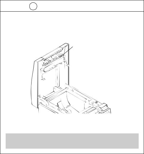
In the position indicated below, a label is provided to alert your attention. Read the cautionary information on it, and handle the printer properly.
This label alerts you to the print head as it becames HOT, and if you touch it, you may get burnt.
HOT AREA:
Be careful not to touch this area to avoid burns as it becomes HOT.
— x —

i DAILY MAINTENANCE
•Prior to start maintenance work, be sure to turn off the printer.
•When cleaning the platen, use a cotton swab applied with ethyl alcohol and wipe off stains.
Platen
 CAUTION:
Avoid cleaning the print head immediately after printing is finished. The print head is HOT.
•Use a dry soft cloth to wipe off stains and dust from the surfaces of the printer covers.
•When wiping clean heavily stained areas, use a cloth which should be dipped in water and then wrung strongly. Never use organic solvents, such as alcohol, thinner, trichlene, benzene, ketone, or chemical dusters.
•If the printer is contaminated with paper dust, use a soft brush to wipe off.
— xi —
i DAILY MAINTENANCE
Cleaning the print head
1Turn off the power of the printer.
2Open the printer cover.
3Using a gauze impregnated with a small amount of alcohol, wipe off stains and dust on the heat-emitting surface of the head.
Printhead
 CAUTION:
Avoid cleaning the print head immediately after printing is finished. The print head is HOT. Do not touch the heat-emitting surface of the head with bare hands or metal objects.
— xii —
THE TABLE OF CONTENTS |
|
|
1. GENERAL OUTLINE ................................................................... |
1 |
|
1.1 |
Features ..................................................................................................... |
1 |
1.2 |
Unpacking .................................................................................................. |
2 |
2. BASIC SPECIFICATIONS ............................................................ |
3 |
|
2.1 |
Model Classification .................................................................................. |
3 |
2.2 |
Basic Specifications .................................................................................. |
4 |
2.3 |
Print Paper Specifications ........................................................................ |
5 |
|
2.3.1 Recommended Paper ....................................................................... |
5 |
|
2.3.2 Print Position and Barcode Printing ................................................ |
6 |
|
2.3.3 Used Paper Form .............................................................................. |
7 |
|
2.3.4 Sensor Position and Cutter Position................................................ |
8 |
3. OUTER APPEARANCE AND COMPONENT PARTS.................. |
9 |
|
3.1 CBM1000S ................................................................................................. |
9 |
|
3.2 CBM1000A / CBM1000D ......................................................................... |
10 |
|
4. OPERATION .............................................................................. |
11 |
|
4.1 Connecting the AC Adapter and AC Power Cord ................................. |
11 |
|
4.2 |
Connecting Interface Cables .................................................................. |
12 |
4.3 |
Connecting the Drawer Kick-Out Connector ......................................... |
13 |
4.4 |
Setting / Replacing Paper Rolls .............................................................. |
14 |
4.5 |
Adjusting the Paper Near-end Sensor ................................................... |
16 |
4.6 Using 58 mm Wide Paper Rolls ............................................................. |
17 |
|
4.7 Removing Paper Jams ............................................................................ |
17 |
|
4.8 |
Cleaning the Print Head .......................................................................... |
18 |
4.9 |
Operation Panel and Error Indication .................................................... |
19 |
4.10 Hexadecimal Dump ............................................................................... |
22 |
|
5. SETTING DIP SWITCHES ......................................................... |
23 |
|
5.1 |
Location of DIP Switches ........................................................................ |
23 |
5.2 |
Table for Setting DIP Switches ............................................................... |
24 |
— xiii —
6. PARALLEL INTERFACE ............................................................. |
27 |
|
6.1 |
Bidirectional Parallel Interface (IEEE1284) ............................................ |
27 |
|
6.1.1 Compatibility Mode (Host → Printer communication : |
|
|
Centronics compliant) .................................................................... |
27 |
|
6.1.2 Reverse Mode (Printer → Host communication) .......................... |
27 |
|
6.1.3 Connector Pin Configuration.......................................................... |
28 |
6.2 |
Description of Input and Output Signals ............................................... |
29 |
|
6.2.1 Input and Output Signals ............................................................... |
29 |
|
6.2.2 Electrical Characteristics................................................................. |
30 |
|
6.2.3 Timing Chart (Compatibility Mode) .............................................. |
31 |
|
6.2.4 Data Reception Control................................................................... |
31 |
|
6.2.5 Buffering .......................................................................................... |
31 |
7. SERIAL INTERFACE .................................................................. |
32 |
|
7.1 |
Specifications .......................................................................................... |
32 |
7.2 |
Connector Pin Configuration .................................................................. |
33 |
7.3 |
Description of Input and Output Signals ............................................... |
34 |
|
7.3.1 Input and Output Signals ............................................................... |
34 |
|
7.3.2 Error Detection ................................................................................ |
35 |
|
7.3.3 Data Reception Control................................................................... |
35 |
|
7.3.4 Buffering .......................................................................................... |
35 |
|
7.3.5 Electrical Characteristics................................................................. |
36 |
8. DRAWER KICK-OUT CONNECTOR AND POWER CONNECTOR... |
37 |
|
8.1 |
Specifications of Drawer Kick-Out Connector ...................................... |
37 |
|
8.1.1 Drawer Kick-Out drive signal ......................................................... |
37 |
|
8.1.2 Electrical characteristics ................................................................. |
37 |
|
8.1.3 Connector Pin Configuration.......................................................... |
37 |
|
8.1.4 Drive Circuit ..................................................................................... |
38 |
8.2 |
Specifications of the Power Connector ................................................. |
38 |
9. MAINTENANCE AND SERVICE ............................................... |
39 |
|
10. PRINT CONTROL FUNCTIONS .............................................. |
40 |
|
10.1 Command List ....................................................................................... |
40 |
|
10.2 Command Details .................................................................................. |
44 |
|
|
10.2.1 Description of Each Item .............................................................. |
44 |
|
10.2.2 Command Details.......................................................................... |
45 |
— xiv —
11. CHARACTER CODES TABLE ................................................ |
148 |
11.1 Code page ............................................................................................ |
148 |
11.1.1 Codepage 00H to 7FH & PC437 (USA, European Standard) ........ |
148 |
11.1.2 Codepage Katakana (Japanese)................................................. |
148 |
11.1.3 Codepage PC850 (Multilingual) ................................................. |
149 |
11.1.4 Codepage PC860 (Portuguese) .................................................. |
149 |
11.1.5 Codepage PC863 (Canadian-French) ......................................... |
150 |
11.1.6 Codepage PC865 (Nordic) .......................................................... |
150 |
11.1.7 Codepage PC852 (Eastern Europe) ............................................ |
151 |
11.1.8 Codepage PC866 (Russian) ........................................................ |
151 |
11.1.9 Codepage PC857 (Turkish) ......................................................... |
152 |
11.1.10 Windows Codepage .................................................................. |
152 |
11.2 International Character Codes Table ................................................. |
153 |
12. APPENDIX 1. PAGE MODE .................................................. |
154 |
12.1 Overview .............................................................................................. |
154 |
12.2 Mapping of print data in the print area ............................................. |
155 |
12.2.1 Example of the Use of PAGE MODE .......................................... |
157 |
13. APPENDIX 2. BIDIRECTIONAL PARALLEL INTERFACE ........ |
160 |
13.1 Overview .............................................................................................. |
160 |
13.1.1 Parallel Interface Communication Modes ................................. |
160 |
13.1.2 Interfacing Phases ....................................................................... |
161 |
13.2 Negotiation .......................................................................................... |
162 |
13.2.1 Overview ...................................................................................... |
162 |
13.2.2 Negotiation Procedure ................................................................ |
162 |
13.2.3 Precautions .................................................................................. |
163 |
13.2.4 Data Communication from Printer to Host ............................... |
164 |
13.2.4.1 Nibble Mode ........................................................................ |
164 |
13.2.4.2 Byte Mode............................................................................ |
165 |
13.2.5 Device ID ...................................................................................... |
166 |
13.2.6 Termination.................................................................................. |
166 |
14. APPENDIX 3. IDENTIFICATION OF SEND STATUS............... |
168 |
15. APPENDIX 4. OUTLINE DRAWING...................................... |
169 |
15.1 CBM1000S ........................................................................................... |
169 |
15.2 CBM1000A / CBM1000D ..................................................................... |
170 |
15.3 AC Adapter (31AD) .............................................................................. |
171 |
16. APPENDIX 5. BLOCK DIAGRAM.......................................... |
172 |
— xv —
|
<<<German>>> |
|
INHALT |
|
|
4. BETRIEB .................................................................................. |
182 |
|
4.1 |
Anschließen des Netzteils und Netzkabels ......................................... |
182 |
4.2 |
Anschließen der Schnittstellenkabel ................................................... |
183 |
4.3 |
Anschließen des Drawer Kickout-Steckers ......................................... |
184 |
4.4 |
Einlegen / Auswechseln von Papierrollen ........................................... |
186 |
4.5 |
Justieren des Papierende-Sensors ...................................................... |
188 |
4.6 |
Verwenden von 58 mm breiten Papierrollen ...................................... |
189 |
4.7 |
Beseitigen von Papierstaus .................................................................. |
189 |
4.8 |
Reinigen des Druckkopfes .................................................................... |
190 |
4.9 |
Bedienungsfeld und Fehleranzeige ..................................................... |
191 |
4.10 Hexdump ............................................................................................. |
194 |
|
5. EINSTELLEN DER DIP-SCHALTER ......................................... |
195 |
|
5.1 |
Position der DIP-Schalter ...................................................................... |
195 |
5.2 |
DIP-Schaltertabelle ................................................................................ |
196 |
6. PARALLELE SCHNITTSTELLE ................................................ |
199 |
|
6.1 |
Bidirektionale parallele Schnittstelle (IEEE1284) ................................ |
199 |
|
6.1.1 Kompatibilitätsmodus (Host → Druckerkommunikation: |
|
|
Centronics-kompatibel) ................................................................ |
199 |
|
6.1.2 Reverse-Modus (Drucker → Hostkommunikation) ..................... |
199 |
|
6.1.3 Belegung der Anschlußstifte........................................................ |
200 |
6.2 |
Beschreibung von Eingangsund Ausgangssignalen ....................... |
201 |
|
6.2.1 Eingangsund Ausgangssignale ................................................. |
201 |
|
6.2.2 Elektrische Kenndaten .................................................................. |
202 |
|
6.2.3 Timing-Tabelle (KompatibilitätsModus) ...................................... |
203 |
|
6.2.4 Datenempfangssteuerung ............................................................ |
203 |
|
6.2.5 Datenpufferspeicher ..................................................................... |
203 |
— xvi —
7. SERIELLE SCHNITTSTELLE ................................................... |
204 |
|
7.1 |
Technische Daten .................................................................................. |
204 |
7.2 |
Belegung der Anschlußstifte ................................................................ |
205 |
7.3 |
Beschreibung der Eingangsund Ausgangssignale .......................... |
206 |
|
7.3.1 Eingangsund Ausgangssignale ................................................. |
206 |
|
7.3.2 Fehlererkennung ........................................................................... |
207 |
|
7.3.3 Datenempfangssteuerung ............................................................ |
207 |
|
7.3.4 Pufferung ....................................................................................... |
207 |
|
7.3.5 Elektrische Kenndaten .................................................................. |
208 |
8. DRAWER KICKOUTANSCHLUSS UND STROMANSCHLUSS ..... |
209 |
|
8.1 |
Technische Daten des Drawer KickOut-Anschlusses ......................... |
209 |
|
8.1.1 Drawer KickOut-Treibersignal ...................................................... |
209 |
|
8.1.2 Elektrische Kenndaten .................................................................. |
209 |
|
8.1.3 Belegung der Anschlußstifte........................................................ |
209 |
|
8.1.4 Treiberschaltung ........................................................................... |
210 |
8.2 |
Technische Daten des Stromanschlusses ........................................... |
210 |
9. WARTUNG UND KUNDENDIENST ....................................... |
211 |
|
Note:
CITIZEN,CITIZEN logo are registered trademark of CITIZEN WATCH CO.,LTD. Windows codepage is a registered trademark of Microsoft Corporation.
— xvii —

1. GENERAL OUTLINE
The CBM1000 is a compact-sized, line thermal printer developed for a variety of applications. It has abundant built-in features, and can be used as a data communication terminal, pos terminal, kitchen terminal and for other applications.
1.1 Features
•Paper drop-in mechanism; when supplying or replacing paper rolls, all you have to do is just drop a paper roll into the printer and close its cover. This will facilitate paper handling and head cleaning greatly.
•High speed (100 mm/s), and low-noise thermal printing.
•Front-side paper ejection method, which allows the printer to be installed and used anywhere with few restrictions.
•Hermetic covering structure, which helps prevent any foreign matter or liquid from getting into the printer.
•Built-in input buffer.
•Bar-code Printing (Possible using special commands).
•Page mode, which allows you to lay out pages freely.
•Registration of user-defined characters and logos into flash memory.
•Built-in Drawer Kick-Out interface.
•Auto cutter mechanism provided as a standard unit.
•Selection possible, as required, from two types: Easy-to-handle, built-in power supply type, and lightweight flat AC adapter type.
•Use of 58 mm wide paper rolls possible by using the partition supplied.
— 1 —
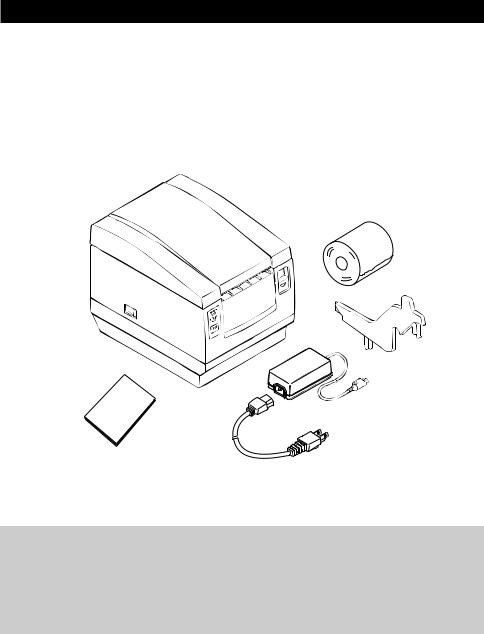
1.2 Unpacking
When unpacking the printer, confirm that the following are provided:
• Printer ............................................................................................ |
1 unit |
• Partition (For 58 mm wide paper roll) ......................................... |
1 piece |
• AC adapter (Provided with the A type only) ............................... |
1 piece |
• AC power cord (Provided with the S type and the A type only) .......... |
1 piece |
• Sample paper roll (Paper width 80 mm) ..................................... |
1 piece |
• User’s manual (This book) ........................................................... |
1 piece |
Printer
Sample paper roll
Partition
AC adapter
User’s manual
AC power code
 CAUTION:
•Install the printer on a flat, sturdy table.
•Do not install the printer near a heater or in a place exposed to direct sunlight.
•Do not use the printer in a high-temperature, high-humidity, or heavily contaminated environment.
•Do not use the printer in an environment where condensation may occur. If condensation should occur, leave the power turned off until condensation evaporates completely.
—2 —
2.BASIC SPECIFICATIONS
2.1Model Classification
The printer models are classified by the following designation method:
CBM1000 - R F 120 S - L
|
|
|
|
|
|
|
|
|
|
|
|
|
|
|
|
|
|
|
|
Model Name |
|
|
|
|
|
|
|
|
|
|
|
|
|
|
|
Label paper function |
|||
|
|
|
|
|
|
|
|
|
|
|
|
|
|
|
|||||
|
|
|
|
|
|
|
|
|
|
|
|
|
|
|
|
|
|
|
no display: Nothing |
|
|
|
|
|
|
|
|
|
|
|
|
|
|
|
|
|
|
|
L: Label interval detection/ |
|
|
|
|
|
|
|
|
|
|
|
|
|
|
|
|
|
|
|
Black mark detection |
|
|
|
|
|
|
|
|
|
|
|
|
|
|
|
|
|
|
|
Power supply*1 |
|
|
|
|
|
|
|
|
|
|
|
|
|
|
|
|
|
|
|
|
|
|
|
|
|
|
|
|
|
|
|
|
|
|
|
|
|
|
|
S: Standard type |
|
|
|
|
|
|
|
|
|
|
|
|
|
|
|
|
|
|
|
(Power supply build-in) |
|
|
|
|
|
|
|
|
|
|
|
|
|
|
|
|
|
|
|
A: AC adapter type |
|
|
|
|
|
|
|
|
|
|
|
|
|
|
|
|
|
|
|
D: DC Input type |
|
|
|
|
|
|
|
|
|
|
|
|
|
|
|
|
|
|
|
(Without AC adapter) |
|
|
|
|
|
|
|
|
|
|
|
|
|
|
|
|
|
|
|
Attached power cord spec*2 |
|
|
|
|
|
|
|
|
|
|
|
|
|
|
|
|
|
|
||
|
|
|
|
|
|
|
|
|
|
|
|
|
|
|
|
|
|
|
120: For AC 120 V |
|
|
|
|
|
|
|
|
|
|
|
|
|
|
|
|
|
|
|
230: For AC 230 V |
|
|
|
|
|
|
|
|
|
|
|
|
|
|
|
|
|
|
|
024: For DC 24 V |
|
|
|
|
|
|
|
|
|
|
|
|
|
|
|
|
|
|
|
Character Set |
|
|
|
|
|
|
|
|
|
|
|
|
|
|
|
|
|
|
||
|
|
|
|
|
|
|
|
|
|
|
|
|
|
|
|
|
|
|
F: International |
|
|
|
|
|
|
|
|
|
|
|
|
|
|
|
|
|
|
|
Interface |
|
|
|
|
|
|
|
|
|
|
|
|
|
|
|
|
|
|
||
|
|
|
|
|
|
|
|
|
|
|
|
|
|
|
|
|
|
|
R: Serial (RS-232C) |
|
|
|
|
|
|
|
|
|
|
|
|
|
|
|
|
|
|
|
P: Parallel |
|
|
|
|
|
|
|
|
|
|
|
|
|
|
|
|
|
|
|
(IEEE 1284 compliant) |
*1 In this user‘s manual, the type of power supply is signified by one of the following: Standard type = S type = CBM1000S
AC adapter type = A type = CBM1000A DC Input type = D type = CBM1000D
*2 Dedicated adapter type and power cord: 31AD-U (AC 120 V 3-wire cord)
31AD-E (AC 230 V Class I cord)
— 3 —
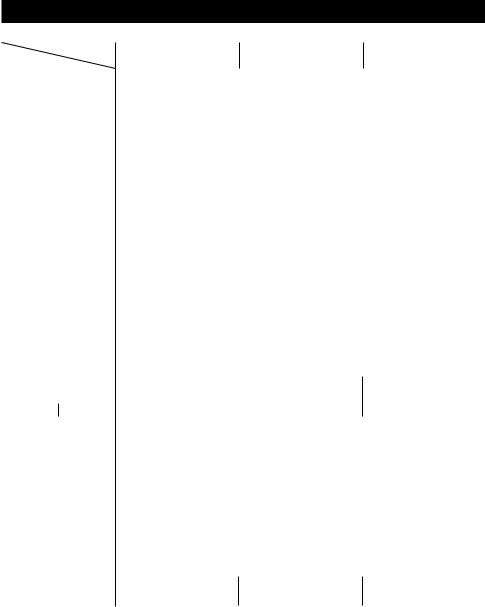
2.2 Basic Specifications
|
Model |
CBM1000-RF120S/A |
CBM1000-RF230S/A |
CBM1000-RF024D |
Item |
CBM1000-PF120S/A |
CBM1000-PF230S/A |
CBM1000-PF024D |
|
Print method |
Line thermal dot print method |
|
||
Print width |
72 mm/576 dots, (54 mm/432 dots)*1 |
|
||
Dot density |
8 × 8 dots/mm (203 dpi) |
|
|
|
Print speed |
100 mm/sec (Fastest, print density level 2), (800 dot lines/sec) |
|||
Number of print |
Font A: 48/42/36/30 columns (12 × 24) |
|
||
columns |
Font B: 64/56/48/40 columns (9 × 24) |
|
||
Character size |
Font A: 1.25 × 3.00 mm; Font B: 0.88 × 3.00 mm |
|
||
Character type |
Alphanumeric characters, International characters, Codepages PC437, |
|||
|
|
Katakana, PC850, PC860, PC863, PC865, PC852, PC866, PC857, and Windows |
||
|
|
codepage |
|
|
Logo registration/print |
Capable of registering user-defined characters and logos into flash memory. |
|||
NV bit map data area |
256K bytes |
|
|
|
Types of bar code |
UPC-A/E, JAN (EAN) 13/8 columns, ITF |
|
||
|
|
CODE 39, CODE 128, CODABAR, CODE 93 |
|
|
Line spacing |
4.23 mm (1/6 inches); selectable using commands. |
|
||
Paper roll |
Thermal paper roll: 80 mm (58 mm) × φ 83 mm |
|
||
|
|
Thermal Label paper roll : 80 mm(58 mm) × φ 83 mm |
|
|
|
|
(See “2.3 Print Paper Specifications”.) |
|
|
Label detection |
None, Label interval detection / Black mark detection |
|
||
Interfacing |
Serial (RS-232C), Parallel (IEEE1284 compliant, Bi-directional communication) |
|||
Input buffer |
4K bytes (72 bytes selectable with a DIP switch) |
|
||
Supply voltage |
S type: AC 120/230 V ±10%; A type/D type: DC 24 V ±7% |
|||
Power consumption |
100 W (Max) |
|
|
|
AC adapter spec. |
Rated input: AC 120 to 240 V, 50/60 Hz, 120 VA |
— |
||
|
|
Rated output: DC 24 V, 1.9 A |
|
|
|
Type |
31AD-U |
31AD-E |
— |
Weight |
S type: Approx. 2.0 kg; |
A type/D type: Approx. 1.4 kg |
||
Outside dimensions |
S type: 145 (W) × 190 (D) × 157 (H) mm |
|
||
|
|
A type/D type: 145 (W) × 190 (D) × 114 (H) mm |
|
|
Operating temperature |
5 to 40°C; 35 to 85% RH (No condensation) |
|
||
and humidity |
|
|
|
|
Storage temperature |
–20 to 60°C; 10 to 90% RH (No condensation) |
|
||
and humidity |
|
|
|
|
Reliability |
Print head life: Pulse resistance 1 × 10⁸ pulses (Print ratio 12.5%) |
|||
|
|
Wear resistance 100 Km (At normal temperature/humidity |
||
|
|
with recommended paper used) |
|
|
|
|
Auto cutter life: 500,000 times of cutting (At normal temperature/humidity |
||
|
|
with recommended paper used) |
|
|
Safety Standard*2 |
UL, C-UL, FCC Class A |
TUV, GS, CE marking |
UL, C-UL, FCC Class A |
|
|
|
TUV, GS, CE marking |
||
|
|
|
|
|
|
|
|
|
|
*1 Represents the value when a 58 mm wide paper roll is used (User selectable). *2 Represents the safety standards acquired when CBM-made adapters (31AD
series) are used.
— 4 —

2.3Print Paper Specifications
2.3.1Recommended Paper
(1) Thermal Paper roll
• Type: |
Heat sensitive paper |
• Paper width: |
80 + 0/– 1 mm; 58 + 0/– 1 mm |
• Paper thickness: |
65 ± 5 µm |
• Roll diameter: |
φ 83 mm or less |
• Print side: |
Outer side of the roll (Top surface) |
• Recommended paper: P220VBB-1/HP220A (From Mitsubishi Paper) |
|
|
TF50KS-E2C (From Nippon Paper) |
|
KF50-HDA (From Oji Paper) |
|
or equivalent types of paper |
• Core size: |
φ12 mm (Inside diameter); φ18 mm (Outside diameter) |
(2) Thermal Lavel paper roll
• Type: |
Heat sensitive paper (Label paper) |
• Paper width: |
80 + 0/– 1 mm; 58 + 0/– 1 mm |
•Label Paper thickness: 65 – 85 µm
•Postebord thickness: 60 µm or less
• Roll diameter: |
φ 83 mm or less |
• Print side: |
Outside of the roll (Top surface) |
• Recommended paper: KPT86S/G63BC P22 (OHJI TUCK) or equivalent type of label paper
• Core size: φ25 – φ28 mm (Outside diameter)
 CAUTION:
•Use of paper other than the specified papers may cause a difference in print density from the CBM specifications. In that case, you can select an appropriate print density with a DIP switch. (See “5. SETTING DIP SWITCHES”)
•Do not stick the end of paper to the core with adhesive paste.
•Avoid allowing the surface of paper to contact with chemicals or oils; otherwise, it may get colored or the printed data on it may become erased.
•Avoid scraping on the surface of paper with your nail or a metal object; otherwise, the surface of heat-sensitive paper may get colored.
•Heat-sensitive paper starts getting colored at approx. 70°C; so, be careful not to expose the paper to the effects from heat, humidity, or sunlight.
— 5 —
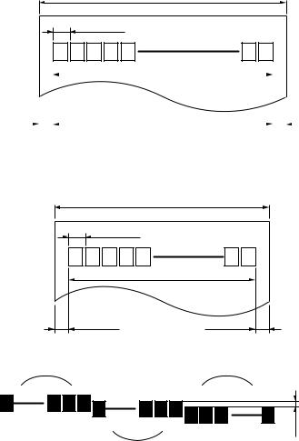
2.3.2 Print Position and Barcode Printing
Roll paper width 80 mm provided:
Paper width 80 mm applies to printing area 72 mm (576 dots), and both left and right margins each ca. 4 mm.
Paper width 80 mm
0.125 mm
|
|
|
|
Print area 72 (63) mm |
|
|
||||
|
|
|
|
|
|
|
|
|
|
The values in ( ) |
|
|
|
|
|
|
|
|
|
|
are for when the |
|
|
|
|
|
|
|
|
|
|
42 column format |
|
|
|
|
|
|
|
|
|
||
|
|
|
4 (8.5) mm |
|
4 (8.5) mm |
|
|
is used. |
||
|
|
|
|
|
|
|
||||
|
|
|
|
|
|
|
|
|
|
|
|
|
|
Figure1 |
Printing Area 1 |
||||||
Roll paper width 58 mm provided:
Paper width 58 mm applies to printing area 54 mm (432 dots), and both left and right margins each ca. 2 mm.
Paper width 58 mm
0.125 mm
Print area 54 (45) mm
2 (2) mm |
2 (11) mm |
The values in ( ) are for when the 30 column format is used.
Figure2 |
Printing Area 2 |
field 1 |
field 3 |
1 |
192 |
385 |
576 |
|
|
||
|
193 |
384 |
Slight shift |
|
|
|
possible. |
|
|
field 2 |
|
Figure3 misaligned printing
Note:Among the adjacent heating elements side by side, for example, 1-192th dot field becomes possibly misaligned with 193-384th dot one and/or 385-576th dot one as shown in fig. 3 (Print Density Level = 2). Make sure not to spread over the printing area of the ladder Bar code onto the different dots fields, otherwise Bar code Printing become misaligned to affect OCR (Optical Character Recognition) performance.
— 6 —
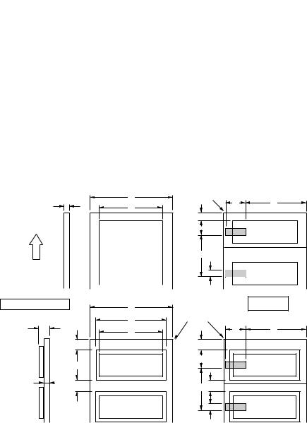
2.3.3 Used Paper Form
unit=mm
|
|
|
|
|
|
|
Thermal Label Paper |
Thermal Label Paper |
|||||||||
Symbol |
Item |
Thermal |
(Label interval detection) |
(Black mark detection) |
|||||||||||||
|
|
|
|
|
|
Paper |
Auto |
|
Tear Bar |
|
Peeler |
Auto |
|
|
Tear Bar |
|
Peeler |
|
|
|
|
|
|
|
cutter |
|
|
cutter |
|
|
|||||
|
|
|
|
|
|
|
|
|
|
|
|
|
|
|
|||
|
|
|
|
|
|
|
|
|
|
|
|
|
|
|
|
|
|
|
|
|
A |
Paper thick |
0.06–0.08 |
|
|
— |
|
|
|
|
— |
|
|||
|
|
|
B |
Label total thick |
— |
|
|
0.14–0.16 |
|
|
|
|
0.14–0.16 |
|
|||
|
|
|
C |
Pasteboard thick |
— |
|
0.065 or less |
|
|
|
0.065 or less |
|
|||||
80mm |
Width |
|
D1 |
Paper width |
79–80 |
|
|
79–80 |
|
|
|
|
79–80 |
|
|||
|
E1 |
Max. label width |
— |
|
78 |
|
|
|
|
78 |
|
|
|||||
|
|
|
|
|
|
|
|
|
|
||||||||
|
|
|
F1 |
Max. print width |
72 |
|
72 |
|
|
|
|
72 |
|
|
|||
58mm |
Width |
D2 |
Paper width |
57–58 |
|
|
57–58 |
|
|
|
|
57–58 |
|
||||
E2 |
Max. label width |
— |
|
56 |
|
|
|
|
56 |
|
|
||||||
|
|
|
|
|
|
|
|
|
|
||||||||
|
|
|
F2 |
Max. print width |
54 |
|
50 |
|
|
|
|
50 |
|
|
|||
|
|
|
G |
Label length |
— |
25–360 |
|
25–50 |
|
25–360 |
|
25–50 |
|||||
|
|
|
H |
label interval length |
— |
|
|
10–30 |
|
|
|
|
10–30 |
|
|||
|
|
|
I |
Black mark length |
4–8 |
|
|
— |
|
|
|
|
4–8 |
|
|||
|
|
|
J |
Black mark size width |
15 or more |
|
|
— |
|
|
|
|
15 or more |
|
|||
|
|
|
K |
Black mark position |
44 |
|
|
— |
|
|
|
44 |
|
|
|||
|
|
|
L |
Black mark pitch |
30–360 |
|
|
— |
|
|
35–360 |
|
35–50 |
||||
|
|
|
|
|
|
||||||||||||
Thermal Paper |
|
Print the black mark in the back side (PCS value: 0.9 or more) |
|||||||||||||||
|
|
|
|
|
|
|
|
|
|
|
|
|
|
|
|
|
|
|
Cutting |
|
D |
position |
K |
A |
J |
|
F |
about |
|
|
|
|
|
10mm |
|
|
about 17mm |
|
L
Paper feed direction
I
Thermal Label Paper |
D |
|
|
|
E |
B |
F |
|
|
about 8mm |
|
G |
Label |
|
|
C |
|
H |
|
|
Label |
Print area
Cutting |
|
position |
|
J |
K |
about 8mm |
|
about 19mm |
|
|
Label |
L H |
|
|
Label |
I |
|
— 7 —
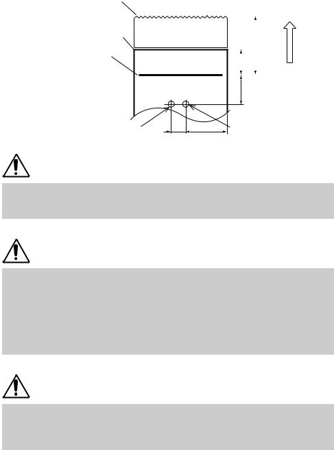
2.3.4 Sensor Position and Cutter Position
Manual cutting position |
Peeler sensor position |
Auto cutting position
Top print line
|
|
|
|
|
|
|
Paper feed direction |
|
|
|
|
|
|
||
|
|
|
|
|
(27mm) |
|
|
|
|
(12mm) |
|
|
|||
|
|
|
|||||
|
|
|
|
|
|||
|
|
(18mm) |
Black mark sensor position (11mm) |
(40mm) |
Label interval |
|
|
Sensor position |
CAUTION:
Observe the following rules on the usage of the auto cutter:
•Every cut paper should be no less than 10 mm in length.
•When cutting a label roll, be sure to cut the base sheet. Never cut labels (tags).
CAUTION:
When using label sheet:
•Be sure to cut the base sheet at every label gap. Otherwise, the cutter performance will be immensely degraded.
•Never open the printer cover while printing as proper print operation may not be guaranteed. Opening the printer cover may alter label length setting or other parameters.
•Never use label rolls with different label sizes or label gaps as proper print operation will not be guaranteed.
CAUTION:
•With a label roll using black marking, the printer could print in label gaps. The user should take the necessary corrective action to avoid this.
•If black marking is used for label sensing, the printer can print over cut lines. This requires the appropriate user adjustment, however.
—8 —
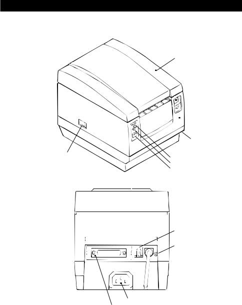
3.OUTER APPEARANCE AND COMPONENT PARTS
3.1CBM1000S
Printer cover
 Ejector
 Top cover
Power box
Power switch |
POWER lamp |
|
|
|
ERROR lamp |
|
FEED switch |
Drawer Kick-Out Connector
Grounding terminal
Inlet
Interface connector
— 9 —
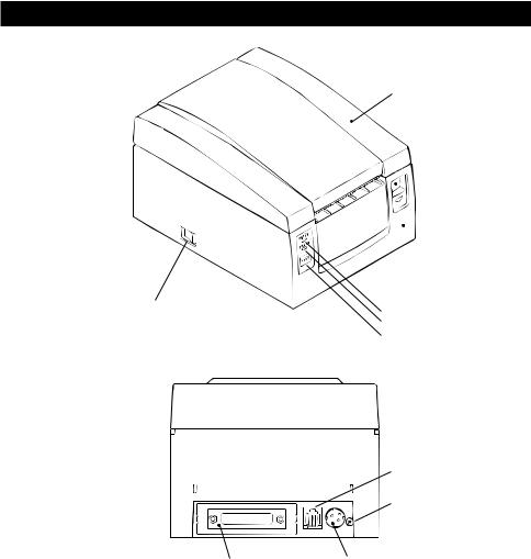
3.2 CBM1000A / CBM1000D
Power switch
Interface connector
Printer cover
 Ejector
 Top cover
POWER lamp
ERROR lamp
FEED switch
Drawer Kick-Out Connector
Grounding terminal
Power connector
— 10 —
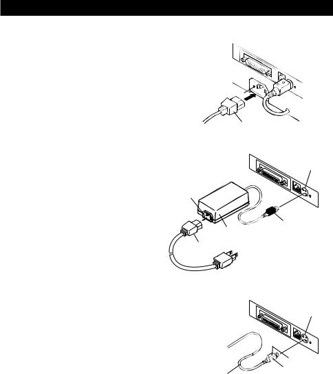
4.OPERATION
4.1Connecting the AC Adapter and AC Power Cord
1 Turn off the power of the printer.
2 For the AC adapter type only: With the flat side of the AC adapter’s cable connector facing upward, insert the cable connector into the power connector on the back side of the printer.
3 For the DC Input type only: Use a cable connector which matches the power connector and can input DC 24 V/1.9 A to the print.
CBM1000S (Standard type)
Inlet
AC power cord
CBM1000A (AC adapter type)
4 Connect the AC power cord to the inlet of the printer or the AC adapter,
and insert the AC power-cord plug Inlet into a suitable wall outlet.
AC adapter |
AC power cord |
Power connector

 Flat side Cable connector
CBM1000D (DC Input type)
|
Power connector |
|
Flat side |
|
Cable connector |
DC 24 V/1.9 A |
|
(Power Voltage) |
|
Power connector: |
TCS7960-53-2010 (Hosiden) or equivalent |
Applicable connector: TCP8927-63-1100 (Hosiden) or equivalent TCP8927-53-1100 (Hosiden) or equivalent
— 11 —
 CAUTION:
•Do not use any AC adapter other than specified.
•When connecting or disconnecting the cable connector of the AC adapter, always pull on the connector, not on the cable.
•The AC power cord should be connected to a wall outlet separated from others used by other equipment which tend to emit noise.
•Avoid pulling on the power cord, or the cord may be damaged or broken, causing a fire, electric shock.
•When the thunder rumbles nearby, disconnect the AC power cord from the wall outlet; otherwise, a thunderbolt may cause a fire or electric shock.
•Avoid placing the power cord near a heating device; otherwise, the cover of the cord may melt, causing a fire or electric shock.
•When you are not going to use the printer for a long period of time, disconnect the AC power cord from the wall outlet for safety.
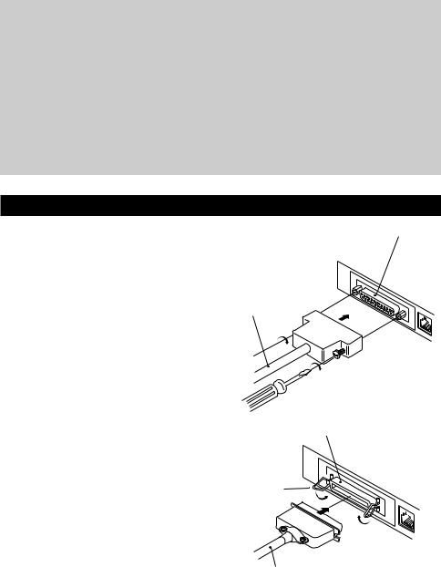
4.2 Connecting Interface Cables
1
2
3
Turn off the power of the printer. (As |
Serial interface connector |
|
well as the host computer |
|
|
connected) |
|
|
Orienting the interface cable |
|
|
terminal correctly, insert it into the |
Serial interface cable |
|
interface connector. |
||
|
||
Secure the cable terminal as shown |
|
|
below. |
|
|
Serial interface cable: Fasten the |
|
|
connector with screws. |
|
|
Parallel interface cable: Hold the |
|
|
connector with clamps. |
|
Connect the other end of the |
Parallel interface connector |
4 interface cable to the host computer. |
|
|
Clamps |
Parallel interface cable
— 12 —
Loading...