


 Loading...
Catalyst 2960-S Switch
Hardware Installation Guide
August 2012
Americas Headquarters
Cisco Systems, Inc. 170 West Tasman Drive
San Jose, CA 95134-1706 USA http://www.cisco.com Tel: 408 526-4000
800 553-NETS (6387) Fax: 408 527-0883
Text Part Number: OL-19732-04
THE SPECIFICATIONS AND INFORMATION REGARDING THE PRODUCTS IN THIS MANUAL ARE SUBJECT TO CHANGE WITHOUT NOTICE. ALL STATEMENTS, INFORMATION, AND RECOMMENDATIONS IN THIS MANUAL ARE BELIEVED TO BE ACCURATE BUT ARE PRESENTED WITHOUT WARRANTY OF ANY KIND, EXPRESS OR IMPLIED. USERS MUST TAKE FULL RESPONSIBILITY FOR THEIR APPLICATION OF ANY PRODUCTS.
THE SOFTWARE LICENSE AND LIMITED WARRANTY FOR THE ACCOMPANYING PRODUCT ARE SET FORTH IN THE INFORMATION PACKET THAT SHIPPED WITH THE PRODUCT AND ARE INCORPORATED HEREIN BY THIS REFERENCE. IF YOU ARE UNABLE TO LOCATE THE SOFTWARE LICENSE OR LIMITED WARRANTY, CONTACT YOUR CISCO REPRESENTATIVE FOR A COPY.
The following information is for FCC compliance of Class A devices: This equipment has been tested and found to comply with the limits for a Class A digital device, pursuant to part 15 of the FCC rules. These limits are designed to provide reasonable protection against harmful interference when the equipment is operated in a commercial environment. This equipment generates, uses, and can radiate radio-frequency energy and, if not installed and used in accordance with the instruction manual, may cause harmful interference to radio communications. Operation of this equipment in a residential area is likely to cause harmful interference, in which case users will be required to correct the interference at their own expense.
The following information is for FCC compliance of Class B devices: The equipment described in this manual generates and may radiate radio-frequency energy. If it is not installed in accordance with Cisco’s installation instructions, it may cause interference with radio and television reception. This equipment has been tested and found to comply with the limits for a Class B digital device in accordance with the specifications in part 15 of the FCC rules. These specifications are designed to provide reasonable protection against such interference in a residential installation. However, there is no guarantee that interference will not occur in a particular installation.
Modifying the equipment without Cisco’s written authorization may result in the equipment no longer complying with FCC requirements for Class A or Class B digital devices. In that event, your right to use the equipment may be limited by FCC regulations, and you may be required to correct any interference to radio or television communications at your own expense.
You can determine whether your equipment is causing interference by turning it off. If the interference stops, it was probably caused by the Cisco equipment or one of its peripheral devices. If the equipment causes interference to radio or television reception, try to correct the interference by using one or more of the following measures:
•Turn the television or radio antenna until the interference stops.
•Move the equipment to one side or the other of the television or radio.
•Move the equipment farther away from the television or radio.
•Plug the equipment into an outlet that is on a different circuit from the television or radio. (That is, make certain the equipment and the television or radio are on circuits controlled by different circuit breakers or fuses.)
Modifications to this product not authorized by Cisco Systems, Inc. could void the FCC approval and negate your authority to operate the product.
The Cisco implementation of TCP header compression is an adaptation of a program developed by the University of California, Berkeley (UCB) as part of UCB’s public domain version of the UNIX operating system. All rights reserved. Copyright © 1981, Regents of the University of California.
NOTWITHSTANDING ANY OTHER WARRANTY HEREIN, ALL DOCUMENT FILES AND SOFTWARE OF THESE SUPPLIERS ARE PROVIDED “AS IS” WITH ALL FAULTS. CISCO AND THE ABOVE-NAMED SUPPLIERS DISCLAIM ALL WARRANTIES, EXPRESSED OR IMPLIED, INCLUDING, WITHOUT LIMITATION, THOSE OF MERCHANTABILITY, FITNESS FOR A PARTICULAR PURPOSE AND NONINFRINGEMENT OR ARISING FROM A COURSE OF DEALING, USAGE, OR TRADE PRACTICE.
IN NO EVENT SHALL CISCO OR ITS SUPPLIERS BE LIABLE FOR ANY INDIRECT, SPECIAL, CONSEQUENTIAL, OR INCIDENTAL DAMAGES, INCLUDING, WITHOUT LIMITATION, LOST PROFITS OR LOSS OR DAMAGE TO DATA ARISING OUT OF THE USE OR INABILITY TO USE THIS MANUAL, EVEN IF CISCO OR ITS SUPPLIERS HAVE BEEN ADVISED OF THE POSSIBILITY OF SUCH DAMAGES.
Cisco and the Cisco logo are trademarks or registered trademarks of Cisco and/or its affiliates in the U.S. and other countries. To view a list of Cisco trademarks, go to this URL: www.cisco.com/go/trademarks. Third-party trademarks mentioned are the property of their respective owners. The use of the word partner does not imply a partnership relationship between Cisco and any other company. (1110R)
Any Internet Protocol (IP) addresses used in this document are not intended to be actual addresses. Any examples, command display output, and figures included in the document are shown for illustrative purposes only. Any use of actual IP addresses in illustrative content is unintentional and coincidental.
Catalyst 2960-S Switch Hardware Installation Guide
© 2010-2012 Cisco Systems, Inc. All rights reserved.

|
|
|
|
|
|
|
|
|
C O N T E N T S |
|||
|
|
|
Preface vii |
|
|
|
|
|
|
|
|
|
|
|
|
Related Publications |
viii |
|
|
|
|
|
|||
|
|
|
Obtaining Documentation and Submitting a Service Request viii |
|||||||||
|
|
Product Overview |
|
|
|
|
|
|
|
|||
C H A P T E R |
1 |
1-1 |
|
|
|
|
|
|
||||
|
|
|
Switch Models |
1-1 |
|
|
|
|
|
|
||
|
|
|
Front Panel |
1-2 |
|
|
|
|
|
|
|
|
|
|
|
10/100 PoE+ Ports |
1-5 |
|
|
|
|
||||
|
|
|
10/100/1000 PoE+ Ports |
1-5 |
|
|
|
|||||
|
|
|
10/100 Ports |
|
1-6 |
|
|
|
|
|
|
|
|
|
|
10/100/1000 Ports |
1-6 |
|
|
|
|
||||
|
|
|
Management Ports 1-7 |
|
|
|
|
|||||
|
|
|
USB Type A Port |
1-8 |
|
|
|
|
|
|||
|
|
|
SFP and SFP+ Module Slots 1-8 |
|||||||||
|
|
|
LEDs |
1-11 |
|
|
|
|
|
|
|
|
|
|
|
System LED |
1-11 |
|
|
|
|
||||
|
|
|
RPS LED |
|
1-12 |
|
|
|
|
|
||
|
|
|
Master LED |
1-12 |
|
|
|
|
|
|||
|
|
|
Port LEDs and Modes |
1-12 |
|
|
|
|||||
|
|
|
Stack LED |
1-15 |
|
|
|
|
|
|||
|
|
|
Console LEDs |
1-16 |
|
|
|
|
||||
|
|
|
Ethernet Management Port LED 1-17 |
|||||||||
|
|
|
Rear Panel |
1-17 |
|
|
|
|
|
|
|
|
|
|
|
FlexStack Ports |
1-19 |
|
|
|
|
|
|||
|
|
|
RPS Connector |
1-19 |
|
|
|
|
|
|||
|
|
|
Cisco RPS 2300 |
1-19 |
|
|
|
|
||||
|
|
|
AC Power Connector |
1-20 |
|
|
|
|||||
|
|
|
Management Options |
1-20 |
|
|
|
|
||||
|
|
|
Network Configurations |
1-21 |
|
|
|
|||||
|
|
Switch Installation |
|
|
|
|
|
|
|
|
||
C H A P T E R |
2 |
|
2-1 |
|
|
|
|
|
|
|||
|
|
|
Preparing |
2-1 |
|
|
|
|
|
|
|
|
|
|
|
Safety Warnings |
2-1 |
|
|
|
|
|
|||
|
|
|
Installation Guidelines |
2-4 |
|
|
|
|||||
|
|
|
|
|
|
|
|
|
Catalyst 2960-S Switch Hardware Installation Guide |
|
|
|
|
|
|
|
|
|
|
|
|
|
|||
|
|
|
|
|
|
|
|
|
|
|
|
|
|
OL-19732-04 |
|
|
|
|
|
|
|
|
iii |
|
|
|
|
|
|
|
|
|
|
|
|
|||

Contents
Box Contents 2-4 |
|
|
|
|
|
Tools and Equipment |
2-4 |
|
|
|
|
Verifying Switch Operation |
2-5 |
|
|
||
Planning a Switch Stack |
2-5 |
|
|
|
|
Stack Guidelines |
2-5 |
|
|
|
|
Installing the FlexStack Module 2-7 |
|
|
|||
Stack Cabling |
2-8 |
|
|
|
|
Stack Bandwidth and Partitioning Examples |
2-8 |
||||
Power-On Sequence for Switch Stacks |
2-10 |
|
|||
Installing the Switch |
2-10 |
|
|
|
|
Rack-Mounting 2-10 |
|
|
|
|
|
Attaching the Rack-Mount Brackets |
2-11 |
||||
Mounting in a Rack |
2-13 |
|
|
||
Wall-Mounting 2-14 |
|
|
|
|
|
Attaching the Brackets for Wall-Mounting |
2-14 |
||||
Attaching the RPS Connector Cover |
2-15 |
|
|||
Mounting on a Wall |
2-16 |
|
|
||
Tableor Shelf-Mounting |
2-17 |
|
|
||
After Switch Installation |
2-17 |
|
|
||
|
|
|
|
|
Connecting the FlexStack Cables |
2-17 |
|
|
|||
|
|
|
|
|
Installing the Power Cord Retainer (Optional) |
2-18 |
|
||||
|
|
|
|
|
Installing SFP and SFP+ Modules |
2-20 |
|
|
|||
|
|
|
|
|
Installing an SFP or SFP+ Module |
2-21 |
|
|
|||
|
|
|
|
|
Removing an SFP or SFP+ Module |
2-21 |
|
|
|||
|
|
|
|
|
Connecting to SFP and SFP+ Modules |
2-22 |
|
|
|||
|
|
|
|
|
Connecting to Fiber-Optic SFP and SFP+ Modules 2-22 |
||||||
|
|
|
|
|
Connecting to 1000BASE-T SFP |
2-23 |
|
|
|||
|
|
|
|
|
10/100 and 10/100/1000 PoE+ Port Connections 2-24 |
||||||
|
|
|
|
|
10/100 and 10/100/1000 Port Connections |
2-26 |
|
||||
|
|
|
|
|
Where to Go Next |
2-26 |
|
|
|
|
|
|
|
Troubleshooting 3-1 |
|
|
|
|
|
|
|||
C H A P T E R 3 |
|
|
|
|
|
|
|
||||
|
|
|
|
|
Diagnosing Problems 3-1 |
|
|
|
|
|
|
|
|
|
|
|
Switch POST Results |
3-1 |
|
|
|
|
|
|
|
|
|
|
Switch LEDs |
3-1 |
|
|
|
|
|
|
|
|
|
|
Switch Connections |
3-2 |
|
|
|
|
|
|
|
|
|
|
Bad or Damaged Cable |
3-2 |
|
|
|
||
|
|
|
|
|
Ethernet and Fiber-Optic Cables 3-2 |
||||||
|
|
|
|
Catalyst 2960-S Switch Hardware Installation Guide |
|
|
|
|
|||
|
|
|
|
|
|
|
|
||||
|
|
|
|
|
|
|
|
|
|
|
|
|
iv |
|
|
|
|
|
|
|
|
OL-19732-04 |
|
|
|
|
|
|
|
|
|
|
|
||

Contents
|
|
Link Status |
3-2 |
|
|
|
|
|
|
|
|
|
|
|
10/100 or 10/100/1000 Port Connections |
3-3 |
|
|
|
||||||
|
|
10/100 or 10/100/1000 PoE Port Connections |
3-3 |
|
|
|||||||
|
|
SFP and SFP+ Module |
|
3-3 |
|
|
|
|
|
|
||
|
|
Interface Settings |
3-3 |
|
|
|
|
|
|
|
||
|
|
Ping End Device |
3-4 |
|
|
|
|
|
|
|
|
|
|
|
Spanning Tree Loops |
3-4 |
|
|
|
|
|
|
|||
|
|
Switch Performance |
3-4 |
|
|
|
|
|
|
|
|
|
|
|
Speed, Duplex, and Autonegotiation |
3-4 |
|
|
|
|
|||||
|
|
Autonegotiation and Network Interface Cards |
3-4 |
|
|
|||||||
|
|
Cabling Distance |
3-5 |
|
|
|
|
|
|
|
||
|
|
Clearing the Switch IP Address and Configuration |
3-5 |
|
|
|
||||||
|
|
Finding the Switch Serial Number |
3-5 |
|
|
|
|
|
|
|||
|
|
Replacing a Failed Stack Member |
3-9 |
|
|
|
|
|
|
|||
|
|
Technical Specifications A-1 |
|
|
|
|
|
|
|
|
||
A P P E N D I X |
A |
|
|
|
|
|
|
|
|
|||
|
|
Connector and Cable Specifications B-1 |
|
|
|
|
|
|||||
A P P E N D I X |
B |
|
|
|
|
|
||||||
|
|
Connector Specifications |
B-1 |
|
|
|
|
|
|
|
|
|
|
|
10/100 Ports (Including PoE) |
B-1 |
|
|
|
|
|
|
|||
|
|
B-2 |
|
|
|
|
|
|
|
|
|
|
|
|
10/100/1000 Ports (Including PoE) |
B-2 |
|
|
|
|
|
||||
|
|
SFP Module Connectors |
B-2 |
|
|
|
|
|
|
|||
|
|
Cables and Adapters |
B-3 |
|
|
|
|
|
|
|
|
|
|
|
SFP Module Cables |
B-3 |
|
|
|
|
|
|
|
|
|
|
|
Cable Pinouts |
B-5 |
|
|
|
|
|
|
|
|
|
|
|
Console Port Adapter Pinouts |
B-6 |
|
|
|
|
|
|
|||
|
|
Configuring the Switch with the CLI-Based Setup Program |
|
|||||||||
A P P E N D I X |
C |
C-1 |
||||||||||
|
|
Accessing the CLI Through Express Setup |
C-1 |
|
|
|
|
|||||
|
|
Accessing the CLI Through the Console Port |
C-1 |
|
|
|
|
|||||
|
|
Connecting the RJ-45 Console Port or USB Console Port |
C-2 |
|||||||||
|
|
Installing the Cisco Microsoft Windows USB Device Driver |
|
C-3 |
||||||||
|
|
Installing the Cisco Microsoft Windows XP USB Driver |
C-3 |
|||||||||
|
|
Installing the Cisco Microsoft Windows 2000 USB Driver |
C-4 |
|||||||||
|
|
Installing the Cisco Microsoft Windows Vista USB Driver |
C-4 |
|||||||||
|
Uninstalling the Cisco Microsoft Windows USB Driver C-5 |
|
|
|
|
|
Uninstalling the Cisco Microsoft Windows XP and 2000 USB Driver |
C-5 |
|||
|
Uninstalling the Cisco Microsoft Windows Vista USB Driver C-5 |
|
|
|
|
|
Catalyst 2960-S Switch Hardware Installation Guide |
|
|
|
|
|
|||||
|
|
|
|
|
|
|
OL-19732-04 |
|
|
v |
|
|
|
|
|
||

Contents
Entering the Initial Configuration Information C-6
IP Settings C-6
Completing the Setup Program C-6
I N D E X
Catalyst 2960-S Switch Hardware Installation Guide
|
vi |
OL-19732-04 |
|
|
|

Preface
This guide is for the networking or computer technician installing the Catalyst 2960-S switch. It documents the physical characteristics of the switch, explains how to install the switch, and provides troubleshooting information.
This guide does not describe system messages that you might receive or how to configure your switch. See the switch software configuration guide, the switch command reference, and the switch system message guide on Cisco.com. For information about the standard Cisco IOS
Release 15.0(2)SE commands, see the Cisco IOS documentation on Cisco.com.
Note Means reader take note. Notes contain helpful suggestions or references to materials not contained in this manual.
Caution Means reader be careful. In this situation, you might do something that could result in equipment damage or loss of data.
IMPORTANT SAFETY INSTRUCTIONS
Warning This warning symbol means danger. You are in a situation that could cause bodily injury. Before you work on any equipment, be aware of the hazards involved with electrical circuitry and be familiar
with standard practices for preventing accidents. Use the statement number provided at the end of each warning to locate its translation in the translated safety warnings that accompanied this device. Statement 1071
SAVE THESE INSTRUCTIONS
The safety warnings for this product are translated into several languages in the Regulatory Compliance and Safety Information for the Catalyst 2960 and 2960-S Switches that ships with the product. The EMC regulatory statements are also included in that guide.
Catalyst 2960-S Switch Hardware Installation Guide
|
OL-19732-04 |
vii |
|

Preface
Related Publications
These documents provide information about the switch and are available from these Cisco.com sites:
http://www.cisco.com/en/US/products/ps6406/tsd_products_support_series_home.html
•Catalyst 2960-S Switch Getting Started Guide
•Regulatory Compliance and Safety Information for the Catalyst 2960 and 2960-S Switches
•Release Notes for the Catalyst 2960-S Switch
•Catalyst 2960 and 2960-S Switch Software Configuration Guide
•Catalyst 2960 and 2960-S Switch Command Reference
•Catalyst 3750, 3560, 3550, 2975, 2970, 2960, and 2960-S Switch System Message Guide
•Device manager online help (available on the switch) http://www.cisco.com/en/US/products/hw/routers/ps2883/prod_installation_guides_list.html
•Cisco Redundant Power System 2300 Hardware Installation Guide
http://www.cisco.com/en/US/products/hw/modules/ps5000/tsd_products_support_series_home.html
• Cisco Small Form-Factor Pluggable Modules Installation Notes http://www.cisco.com/en/US/products/hw/modules/ps5455/products_device_support_tables_list.html
•Cisco Gigabit Ethernet Transceiver Modules Compatibility Matrix
•Cisco 100-Megabit Ethernet SFP Modules Compatibility Matrix
•Cisco Small Form-Factor Pluggable Modules Compatibility Matrix
•Compatibility Matrix for 1000BASE-T Small Form-Factor Pluggable Modules
•Cisco CWDM SFP Transceiver Compatibility Matrix
Obtaining Documentation and Submitting a Service Request
For information on obtaining documentation, submitting a service request, and gathering additional information, see the monthly What’s New in Cisco Product Documentation, which also lists all new and revised Cisco technical documentation, at:
http://www.cisco.com/en/US/docs/general/whatsnew/whatsnew.html
Subscribe to the What’s New in Cisco Product Documentation as a Really Simple Syndication (RSS) feed and set content to be delivered directly to your desktop using a reader application. The RSS feeds are a free service and Cisco currently supports RSS Version 2.0.
Catalyst 2960-S Switch Hardware Installation Guide
|
viii |
OL-19732-04 |
|
|
|

C H A P T E R 1
Product Overview
The Catalyst 2960-S family of switches, also referred to as the switch, are Ethernet switches to which you can connect devices such as Cisco IP Phones, Cisco Wireless Access Points, workstations, and other network devices such as servers, routers, and other switches.
Some models of the switches support stacking through the Cisco FlexStack technology. Unless otherwise noted, the term switch refers to a standalone switch and to a switch stack.
•Switch Models, page 1-1
•Front Panel, page 1-2
•Rear Panel, page 1-17
•Management Options, page 1-20
Switch Models
Table 1-1 |
Switch Models and Descriptions |
|
|
|
|
||
|
|
|
|
|
|
|
|
|
|
|
Supported |
|
|
|
|
|
Switch Model |
|
Software Image |
Description |
|
||
|
|
|
|
|
|||
|
Catalyst 2960S-48FPD-L1 |
LAN Base |
48 10/100/1000 Power over Ethernet Plus (PoE+) ports (PoE budget of |
|
|||
|
|
|
|
740 W) and 2 small form-factor pluggable (SFP)+2 module slots. |
|
||
|
Catalyst 2960S-48LPD-L1 |
LAN Base |
48 10/100/1000 PoE+ ports (PoE budget of 370 W) and 2 SFP+ module |
|
|||
|
|
|
|
slots |
|
||
|
|
|
|
|
|||
|
Catalyst 2960S-24PD-L1 |
LAN Base |
24 10/100/1000 PoE+ ports (PoE budget of 370 W) and 2 SFP+ module |
|
|||
|
|
|
|
slots |
|
||
|
|
|
|
|
|||
|
Catalyst 2960S-48TD-L1 |
LAN Base |
48 10/100/1000 ports and 2 SFP+ module slots |
|
|||
|
Catalyst 2960S-24TD-L1 |
LAN Base |
24 10/100/1000 ports and 2 SFP+ module slots |
|
|||
|
Catalyst 2960S-48FPS-L1 |
LAN Base |
48 10/100/1000 PoE+ ports (PoE budget of 740 W) and 4 SFP3 module |
|
|||
|
|
|
|
slots |
|
||
|
|
|
|
|
|||
|
Catalyst 2960S-48LPS-L1 |
LAN Base |
48 10/100/1000 PoE+ ports (PoE budget of 370 W) and 4 SFP module |
|
|||
|
|
|
|
slots |
|
||
|
|
|
|
|
|||
|
Catalyst 2960S-24PS-L1 |
LAN Base |
24 10/100/1000 PoE+ ports (PoE budget of 370 W) and 4 SFP module |
|
|||
|
|
|
|
slots |
|
||
|
|
|
|
|
|||
|
Catalyst 2960S-48TS-L1 |
LAN Base |
48 10/100/1000 ports and 4 SFP module slots |
|
|||
|
|
|
|
Catalyst 2960-S Switch Hardware Installation Guide |
|
|
|
|
|
|
|
|
|
||
|
|
|
|
|
|
|
|
|
OL-19732-04 |
|
|
|
|
1-1 |
|
|
|
|
|
|
|
||
Chapter 1 Product Overview
Front Panel
Table 1-1 |
Switch Models and Descriptions (continued) |
|||
|
|
|
|
|
|
|
Supported |
|
|
Switch Model |
|
Software Image |
Description |
|
|
|
|
|
|
Catalyst 2960S-24TS-L1 |
LAN Base |
24 |
10/100/1000 ports and 4 SFP module slots |
|
Catalyst 2960S-48TS-S |
LAN Lite |
48 |
10/100/1000 ports and 2 SFP module slots |
|
|
|
|
|
|
Catalyst 2960S-24TS-S |
LAN Lite |
24 |
10/100/1000 ports and 2 SFP module slots |
|
|
|
|
|
|
Catalyst 2960S-F48FPS-L1 |
LAN Base |
48 |
10/100 PoE+ ports (PoE budget of 740 W) and 4 SFP module slots |
|
Catalyst 2960S-F48LPS-L1 |
LAN Base |
48 |
10/100 PoE+ ports (PoE budget of 370 W) and 4 SFP module slots |
|
Catalyst 2960S-F48TS-L1 |
LAN Base |
48 |
10/100 ports and 4 SFP module slots |
|
Catalyst 2960S-F24PS-L1 |
LAN Base |
24 |
10/100 PoE+ ports (PoE budget of 370 W) and 2 SFP module slots |
|
Catalyst 2960S-F24TS-L1 |
LAN Base |
24 |
10/100 ports and 2 SFP module slots |
|
Catalyst 2960S-F48TS-S |
LAN Lite |
48 |
10/100 ports and 2 SFP module slots |
|
|
|
|
|
|
Catalyst 2960S-F24TS-S |
LAN Lite |
24 |
10/100 ports and 2 SFP module slots |
|
|
|
|
|
|
1.Support Cisco FlexStack technology.
2.SFP+ = 10 Gigabit uplink.
3.SFP = 1 Gigabit uplink.
Front Panel
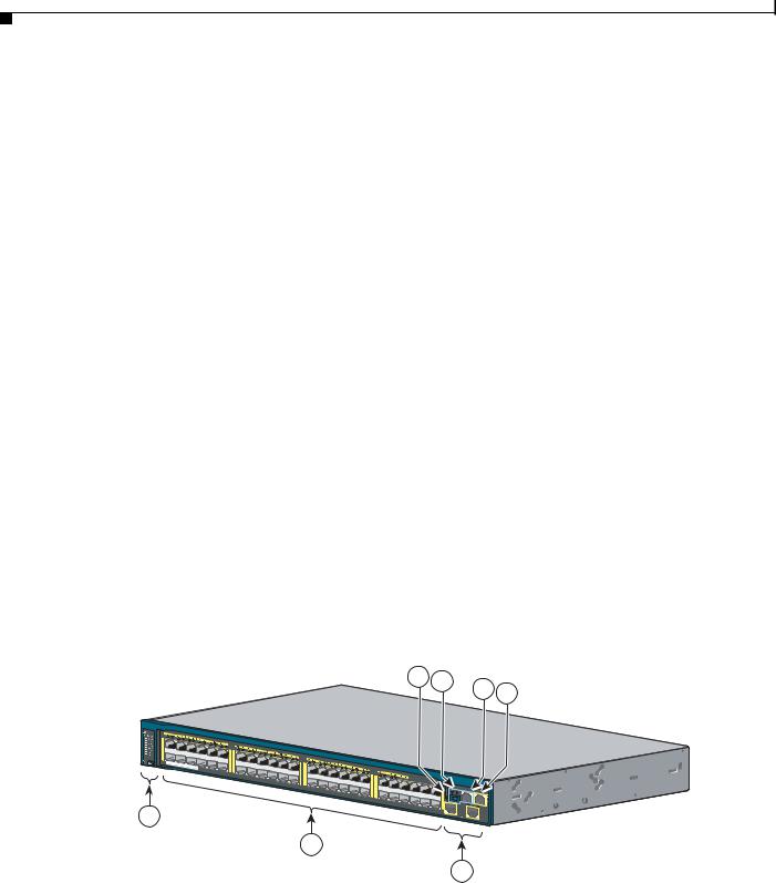
The 24and 48-port switch front panels include the 10/100 or the 10/100/1000 Ethernet ports, or the 10/100 or 10/100/1000 PoE ports, SFP or SFP+ module slots, the universal serial bus (USB) ports, the console ports, and the LEDs. All the 24and 48-port switches have similar components. See Figure 1-1, Figure 1-2, Figure 1-3, and Figure 1-4 for examples.
Figure 1-1 Catalyst 2960S-48FPD-L Front Panel
4 |
5 |
6 |
7 |
|
|
1X |
|
|
|
|
|
|
|
11X |
13X |
|
|
2X |
|
|
|
|
|
POWER |
OVER |
ETHERNET 740W |
23X |
25X |
|
|
|
|
|
|
|
|
|
12X |
14X |
|
|
|
|
|
|
36X |
38X |
|
|
|
24X |
26X |
|
|
|
|
|
37X |
39X |
1
2


 Catalyst 2960-S
47X
48X
1
3
Series
2
PoE 10G
206693
|
1 |
Mode button and switch LEDs |
5 |
USB mini-Type B (console) port |
|
||||
|
|
|
|
|
|
||||
|
2 |
10/100/1000 PoE+ ports1 |
6 |
RJ-45 console port |
|
||||
3 |
SFP+ module slots |
7 |
Ethernet management port |
||||||
|
|
|
|
|
|
|
|||
4 |
USB Type A port |
|
|
|
|
||||
|
|
|
|
|
|
|
|
|
|
|
|
|
Catalyst 2960-S Switch Hardware Installation Guide |
|
|
|
|
||
|
|
|
|
|
|
|
|||
|
|
|
|
|
|
|
|
|
|
|
1-2 |
|
|
|
|
|
|
OL-19732-04 |
|
|
|
|
|
|
|
|
|||
Chapter 1 Product Overview
Front Panel
1.Port numbering is from left to right, with port 1 on the far left. The first member of the pair (port 1) is above the second member (port 2). Module slot numbers are 1 and 2.
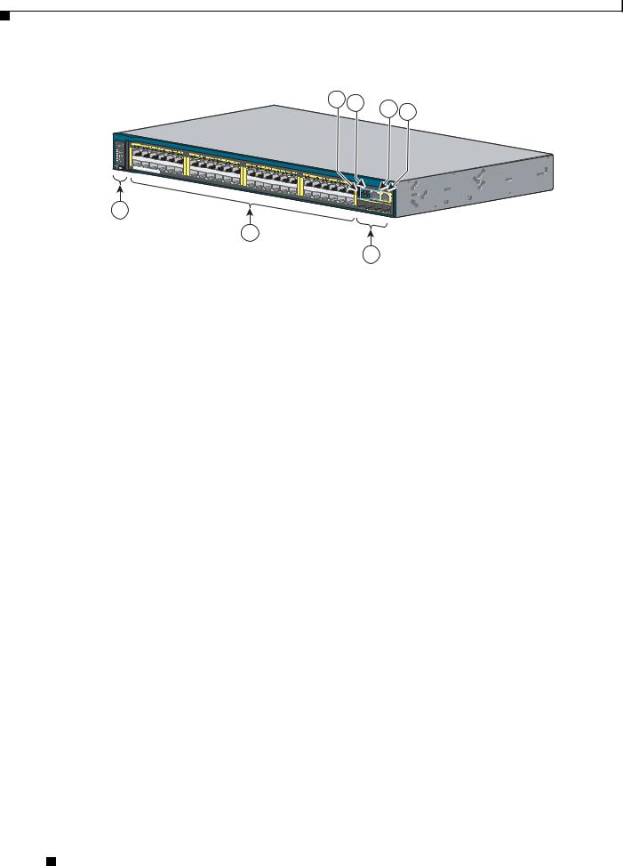
Figure 1-2 Catalyst 2960S-48TS-L Front Panel
|
|
|
|
4 |
5 |
|
6 |
7 |
|
|
|
|
|
|
|
||
1X |
|
|
|
|
|
|
|
|
|
11X |
13X |
|
|
|
|
|
|
2X |
|
|
|
|
|
|
|
|
POWER OVER |
ETHERNET 740W |
23X |
25X |
|
|
|
|
|
|
|
|
|
|
|
|
|
|
|
12X |
14X |
|
|
|
|
|
|
|
|
|
36X |
38X |
|
|
|
|
|
|
24X |
26X |
|
|
Catalyst |
2960- |
|
|
|
|
|
|
47X |
|
S Series |
|
|
|
|
37X |
39X |
|
|
|
|
1 |
|
|
|
|
48X |
|
|
|
|
|
|
|
|
49 |
52 |
|
|
|
|
|
|
|
|
50 |
51 |
|
|
|
|
|
|
|
|
|
2
3
206694
1 |
Mode button and switch LEDs |
5 |
USB mini-Type B (console) port |
|
|
|
|
2 |
10/100/1000 ports1 |
6 |
RJ-45 console port |
3 |
SFP module slots |
7 |
Ethernet management port |
|
|
|
|
4 |
USB Type A port |
|
|
|
|
|
|
1.Port numbering is from left to right, with port 1 on the far left. The first member of the pair (port 1) is above the second member (port 2). Module slot numbers are 49, 50, 51, and 52.
Figure 1-3 Catalyst 2960S-48TS-S Front Panel
|
|
|
|
4 |
5 |
|
6 |
7 |
|
|
|
|
|
|
|
||
1X |
|
|
|
|
|
|
|
|
|
11X |
13X |
|
|
|
|
|
|
2X |
|
|
|
|
|
|
|
|
POWER OVER |
ETHERNET 740W |
23X |
25X |
|
|
|
|
|
|
|
|
|
|
|
|
|
|
|
12X |
14X |
|
|
|
|
|
|
|
|
|
36X |
38X |
|
|
|
|
|
|
24X |
26X |
|
|
Catalyst |
2960-S |
|
|
|
|
|
|
|
|||
|
|
|
|
|
47X |
|
Series SI |
|
|
|
|
37X |
39X |
|
|
|
|
1 |
|
|
|
|
48X |
|
|
|
|
|
|
|
|
49 |
|
|
|
|
|
|
|
|
|
|
50 |
|
2
3
206695
1 |
Mode button and switch LEDs |
5 |
USB mini-Type B (console) port |
|
|
|
|
2 |
10/100/1000 ports1 |
6 |
RJ-45 console port |
3 |
SFP module slots |
7 |
Ethernet management port |
|
|
|
|
4 |
USB Type A port |
|
|
|
|
|
|
1.Port numbering is from left to right, with port 1 on the far left. The first member of the pair (port 1) is above the second member (port 2). Module slot numbers are 49 and 50.
Catalyst 2960-S Switch Hardware Installation Guide
|
OL-19732-04 |
1-3 |
|
|
|
Chapter 1 Product Overview
Front Panel
Figure 1-4 Catalyst 2960S-F48FPS-L Front Panel
|
|
|
|
4 |
5 |
6 |
7 |
|
|
|
|
|
|
||
1X |
|
|
|
|
|
|
|
|
11X |
13X |
|
|
|
|
|
2X |
|
|
|
|
|
|
|
POWER OVER |
ETHERNET 740W |
23X |
25X |
|
|
|
|
|
|
|
|
|
|
|
|
|
12X |
14X |
|
|
|
|
|
|
|
|
36X |
38X |
|
|
|
|
|
24X |
26X |
|
|
Catalyst |
|
|
|
|
37X |
39X |
|
|
|
|
|
|
|
|
48X |
|
|
1
2
3
344240
1 |
Mode button and switch LEDs |
5 |
USB mini-Type B (console) port |
|
|
|
|
2 |
10/100 POE+ ports1 |
6 |
RJ-45 console port |
3 |
SFP module slots |
7 |
Ethernet management port |
|
|
|
|
4 |
USB Type A port |
|
|
|
|
|
|
1.Port numbering is from left to right, with port 1 on the far left. The first member of the pair (port 1) is above the second member (port 2). Module slot numbers are 49, 50, 51, and 52.
Catalyst 2960-S Switch Hardware Installation Guide
1-4 |
OL-19732-04 |
|
|

Chapter 1 Product Overview
Front Panel
10/100 PoE+ Ports
The ports provide PoE+ support for devices compliant with IEEE 802.3af, IEEE 802.3at, and ePoE and also provide Cisco prestandard PoE support for Cisco IP Phones and Cisco Aironet Access Points.
The maximum switch power output is either 740 W or 370 W, depending on the switch model. Intelligent power management allows flexible power allocation across all ports.
For switches with a 740 W power budget, you can budget the PoE and PoE+:
•15.4 W of PoE output on all ports
•30 W of PoE+ on 24 ports
For switches with a 370 W power budget, you can budget the PoE and PoE+:
•15.4 W of PoE output on 24 ports
•7.7 W of PoE output on 48 ports
•30 W of PoE+ on 12 ports
•Total power budget can be allocated among the ports
On a per-port basis, you control whether or not a port automatically provides power when an IP phone or an access point is connected.
The 10/100 PoE ports use RJ-45 connectors with Ethernet pinouts. The maximum cable length is 328 feet (100 meters). The 10BASE-T and 100BASE-TX traffic requires Category 5, Category 5e, or Category 6 unshielded twisted pair (UTP) cable. The 10BASE-T traffic can use Category 3 or Category 4 UTP cable.
Cisco intelligent power management capabilities include enhanced power negotiation, power reservation, and per-port power policing. For information about configuring and monitoring PoE ports, see the switch software configuration guide on Cisco.com.
For information about port connections and port specifications, see the “10/100 and 10/100/1000 PoE+ Port Connections” section on page 2-24 and Appendix B, “Connector and Cable Specifications.”
Note The output of the PoE circuit has been evaluated as a Limited Power Source (LPS) per IEC 60950-1.
10/100/1000 PoE+ Ports
The ports provide PoE+ support for devices compliant with IEEE 802.3af, IEEE 802.3at, and ePoE and also provide Cisco prestandard PoE support for Cisco IP Phones and Cisco Aironet Access Points.
The maximum switch power output is either 740 W or 370 W, depending on the switch model. Intelligent power management allows flexible power allocation across all ports.
For switches with a 740 W power budget, you can budget the PoE and PoE+:
•15.4 W of PoE output on all ports
•30 W of PoE+ on 24 ports
For switches with a 370 W power budget, you can budget the PoE and PoE+:
•15.4 W of PoE output on 24 ports
•7.7 W of PoE output on 48 ports
•30 W of PoE+ on 12 ports
Catalyst 2960-S Switch Hardware Installation Guide
|
OL-19732-04 |
1-5 |
|
|
|

Chapter 1 Product Overview
Front Panel
• Total power budget can be allocated among the ports
On a per-port basis, you control whether or not a port automatically provides power when an IP phone or an access point is connected.
The 10/100/1000 PoE ports use RJ-45 connectors with Ethernet pinouts. The maximum cable length is 328 feet (100 meters). The 100BASE-TX and 1000BASE-T traffic requires Category 5, Category 5e, or Category 6 unshielded twisted pair (UTP) cable. The 10BASE-T traffic can use Category 3 or Category 4 UTP cable.
Cisco intelligent power management capabilities include enhanced power negotiation, power reservation, and per-port power policing. For information about configuring and monitoring PoE ports, see the switch software configuration guide on Cisco.com.
For information about port connections and port specifications, see the “10/100 and 10/100/1000 PoE+ Port Connections” section on page 2-24 and Appendix B, “Connector and Cable Specifications.”
Note The output of the PoE circuit has been evaluated as a Limited Power Source (LPS) per IEC 60950-1.
10/100 Ports
The 10/100 ports use RJ-45 connectors with Ethernet pinouts. The maximum cable length is 328 feet (100 meters). The 100BASE-TX traffic requires Category 5, Category 5e, or Category 6 unshielded twisted pair (UTP) cable. The 10BASE-T traffic can use Category 3 or
Category 4 UTP cable.
For information about port connections and port specifications, see the “10/100 and 10/100/1000 Port Connections” section on page 2-26 and Appendix B, “Connector and Cable Specifications.”
10/100/1000 Ports
The 10/100/1000 ports use RJ-45 connectors with Ethernet pinouts. The maximum cable length is 328 feet (100 meters). The 100BASE-TX and 1000BASE-T traffic requires Category 5, Category 5e, or Category 6 unshielded twisted pair (UTP) cable. The 10BASE-T traffic can use Category 3 or Category 4 UTP cable.
For information about port connections and port specifications, see the “10/100 and 10/100/1000 Port Connections” section on page 2-26 and Appendix B, “Connector and Cable Specifications.”
Catalyst 2960-S Switch Hardware Installation Guide
1-6 |
OL-19732-04 |
|
|

Chapter 1 Product Overview
Front Panel
Management Ports
•Ethernet management port
•RJ-45 console port (EIA/TIA-232)
•USB mini-Type B console port (5-pin connector)
You can connect the switch to a host such as a Windows workstation or a terminal server through the Ethernet management port, the RJ-45 console port, or the USB console port (USB mini-Type B port). The 10/100 Ethernet management port connection uses a standard RJ-45 crossover or straight-through cable. The RJ-45 console port connection uses the supplied RJ-45-to-DB-9 female cable. The USB console port connection uses a USB Type A to 5-pin mini-Type B cable. The USB console interface speeds are the same as the RJ-45 console interface speeds.
If you use the USB console port, the Cisco Windows USB device driver must be installed on any PC connected to the console port (for operation with Microsoft Windows).
Note For information about downloading the Cisco USB device driver, see the “Installing the Cisco Microsoft Windows USB Device Driver” section on page C-3.
With the Cisco Windows USB device driver, you can connect and disconnect the USB cable from the console port without affecting Windows HyperTerminal operations. Mac OS X or Linux require no special drivers.
The console output always goes to both the RJ-45 and the USB console connectors, but the console input is active on only one of the console connectors at any one time. The USB console takes precedence over the RJ-45 console. When a cable is connected into the USB console port, the RJ-45 console port becomes inactive. Conversely, when the USB cable is disconnected from the USB console port, the RJ-45 port becomes active.
Note The 4-pin mini-Type B connectors resemble 5-pin mini-Type B connectors. They are not compatible. Use only the 5-pin mini-Type B. See Figure 1-5.
Figure 1-5 USB Mini-Type B Port
 253163
You can use the command-line interface (CLI) to configure an inactivity timeout which reactivates the RJ-45 console if the USB console has been activated and no input activity has occurred on the USB console for a specified time period.
After the USB console deactivates due to inactivity, you cannot use the CLI to reactivate it. Disconnect and reconnect the USB cable to reactivate the USB console. For information on using the CLI to configure the USB console interface, see the switch software guide.
Catalyst 2960-S Switch Hardware Installation Guide
|
OL-19732-04 |
1-7 |
|
|
|
Chapter 1 Product Overview
Front Panel
USB Type A Port
The USB Type A interface provides access to external USB FLASH devices (also known as thumb drives or USB keys).
The interface supports Cisco USB flash drives with capacities from 64 MB to 1 GB.
Cisco IOS software provides standard file system access to the flash device: read, write, erase, and copy, as well as the ability to format the flash device with a FAT file system.
For more information about the switch management ports, see the switch software configuration guide and the command reference on Cisco.com and the “Connector and Cable Specifications” section on page B-1.
SFP and SFP+ Module Slots
The switch has either two or four 1-Gigabit SFP or two 10-Gigabit SFP+ module slots. The slots marked SFP+ support both SFP and SFP+ modules. The SFP slots support only the SFP modules. Figure 1-6 shows a switch with the SFP+ slots.
Figure 1-6 |
SFP+ Slots |
|
47X |
48X
1
2
10G
276815
1
1 SFP+ module slots
Catalyst 2960-S Switch Hardware Installation Guide
1-8 |
OL-19732-04 |
|
|

Chapter 1 Product Overview
Front Panel
Table 1-2 lists the switches that support the SFP modules. Table 1-3 lists the switches that support the SFP+ modules.
|
|
Table 1-2 |
Supported SFP Modules |
|||||
|
|
|
|
|
|
|||
|
|
Switch Models |
|
Supported SFP Modules |
||||
|
|
|
|
|
||||
|
|
All 2960-S models |
GLC-LH-SM= |
|||||
|
|
|
|
GLC-SX-MM= |
||||
|
|
|
|
|
||||
|
|
Catalyst 2960S-48FPS-L |
GLC-BX-D= |
|||||
|
|
Catalyst 2960S-48LPS-L |
GLC-BX-U= |
|||||
|
|
Catalyst 2960S-24PS-L |
GLC-ZX-SM= |
|||||
|
|
Catalyst 2960S-48TS-L |
CWDM-SFP-1470= |
|||||
|
|
Catalyst 2960S-24TS-L |
CWDM-SFP-1490= |
|||||
|
|
Catalyst 2960S-F48FPS-L |
CWDM-SFP-1510= |
|||||
|
|
Catalyst 2960S-F48LPS-L |
CWDM-SFP-1530= |
|||||
|
|
Catalyst 2960S-F24PS-L |
CWDM-SFP-1550= |
|||||
|
|
Catalyst 2960S-F48TS-L |
CWDM-SFP-1570= |
|||||
|
|
Catalyst 2960S-F24TS-L |
CWDM-SFP-1590= |
|||||
|
|
Catalyst 2960S-48FPD-L |
CWDM-SFP-1610= |
|||||
|
|
Catalyst 2960S-48LPD-L |
|
|
|
|
|
|
|
|
Catalyst 2960S-24PD-L |
|
|
|
|
|
|
|
|
Catalyst 2960S-48TD-L |
|
|
|
|
|
|
|
|
Catalyst 2960S-24TD-L |
|
|
|
|
|
|
|
|
|
|
|
||||
|
|
Catalyst 2960S-48FPS-L |
GLC-FE-100BX-D= |
|||||
|
|
Catalyst 2960S-48LPS-L |
GLC-FE-100BX-U= |
|||||
|
|
Catalyst 2960S-24PS-L |
GLC-FE-100LX= |
|||||
|
|
Catalyst 2960S-48TS-L |
|
|
|
|
|
|
|
|
Catalyst 2960S-24TS-L |
|
|
|
|
|
|
|
|
Catalyst 2960S-F48FPS-L |
|
|
|
|
|
|
|
|
Catalyst 2960S-F48LPS-L |
|
|
|
|
|
|
|
|
Catalyst 2960S-F24PS-L |
|
|
|
|
|
|
|
|
Catalyst 2960S-F48TS-L |
|
|
|
|
|
|
|
|
Catalyst 2960S-F24TS-L |
|
|
|
|
|
|
|
|
|
|
|
||||
|
|
Catalyst 2960S-48FPS-L |
GLC-GE-100FX= |
|||||
|
|
Catalyst 2960S-48LPS-L |
GLC-FE-100FX= |
|||||
|
|
Catalyst 2960S-24PS-L |
GLC-T= |
|||||
|
|
Catalyst 2960S-48TS-L |
|
|
|
|
|
|
|
|
Catalyst 2960S-24TS-L |
|
|
|
|
|
|
|
|
Catalyst 2960S-48TS-S |
|
|
|
|
|
|
|
|
Catalyst 2960S-24TS-S |
|
|
|
|
|
|
|
|
Catalyst 2960S-F48FPS-L |
|
|
|
|
|
|
|
|
Catalyst 2960S-F48LPS-L |
|
|
|
|
|
|
|
|
Catalyst 2960S-F24PS-L |
|
|
|
|
|
|
|
|
Catalyst 2960S-F48TS-L |
|
|
|
|
|
|
|
|
Catalyst 2960S-F24TS-L |
|
|
|
|
|
|
|
|
Catalyst 2960S-F48TS-S |
|
|
|
|
|
|
|
|
Catalyst 2960S-F24TS-S |
|
|
|
|
|
|
|
|
|
|
|
||||
|
|
Catalyst 2960S-48TS-S |
GLC-ZX-SM= |
|||||
|
|
Catalyst 2960S-24TS-S |
|
|
|
|
|
|
|
|
Catalyst 2960S-F48TS-S |
|
|
|
|
|
|
|
|
Catalyst 2960S-F24TS-S |
|
|
|
|
|
|
|
|
|
|
|
|
|
|
|
|
|
|
|
Catalyst 2960-S Switch Hardware Installation Guide |
|
|
||
|
|
|
|
|
||||
|
|
|
|
|
|
|
|
|
|
OL-19732-04 |
|
|
|
|
1-9 |
|
|
|
|
|
|
|
|
|||

Chapter 1 Product Overview
Front Panel
Table 1-3 |
Supported SFP+ Modules |
|
|
|
|
Switch Models |
|
Supported SFP+ Modules |
|
|
|
Catalyst 2960S-48FPD-L |
SFP-10G-LR= |
|
Catalyst 2960S-48LPD-L |
SFP-10G-SR= |
|
Catalyst 2960S-24PD-L |
SFP-10G-LRM= |
|
Catalyst 2960S-48TD-L |
SFP-H10GB-CU1M= |
|
Catalyst 2960S-24TD-L |
SFP-H10GB-CU3M= |
|
|
|
SFP-H10GB-CU5M= |
|
|
|
For information about SFP modules, see the SFP module documentation and the “Installing SFP and SFP+ Modules” section on page 2-20. For cable specifications, see Appendix B, “Connector and Cable Specifications.”
|
Catalyst 2960-S Switch Hardware Installation Guide |
1-10 |
OL-19732-04 |

Chapter 1 Product Overview
Front Panel
LEDs
You can use the switch LEDs to monitor switch activity and its performance. Figure 1-7 shows the switch LEDs and the Mode button that you use to select a port mode.
Figure 1-7 Switch LEDs and Mode Button
10
1 |
|
2 |
|
3 |
|
4 |
|
5 |
|
6 |
|
7 |
|
8 |
9 |
1X
2X
POWER
OVER
11X
ETHERNET |
740W |
|
12X
206758
1 |
System LED |
6 |
Speed LED |
2 |
RPS1 LED |
7 |
Stack LED2 |
3 |
Master LED2 |
8 |
PoE LED3 |
4 |
Status LED |
9 |
Mode button |
5 |
Duplex LED |
|
|
1.RPS = redundant power system—only on switch models that support RPS.
2.Only on switch models that support stacking.
3.Only on switch models that support PoE.
System LED
Table 1-4 System LED
|
|
Color |
System Status |
|
|||
|
|
|
|
|
|||
|
|
Off |
System is not powered on. |
||||
|
|
|
|
|
|||
|
|
Green |
System is operating normally. |
||||
|
|
|
|
|
|||
|
|
Amber |
System is receiving power but is not functioning properly. |
||||
|
|
|
|
|
|
|
|
|
|
|
Catalyst 2960-S Switch Hardware Installation Guide |
|
|
||
|
|
|
|
||||
|
|
|
|
|
|
|
|
|
OL-19732-04 |
|
|
|
1-11 |
|
|
|
|
|
|
|
|||

Chapter 1 Product Overview
Front Panel
For information on the System LED colors during power-on self-test (POST), see the “Switch POST Results” section on page 3-1.
RPS LED
Note The RPS LED is not present on the Catalyst 2960S-F48FPS-L, 2960S-F48LPS-L, 2960S-F24PS-L, 2960S-F48TS-L, 2960S-F24TS-L, 2960S-F48TS-S, and 2960S-F24TS-S switches—these models do not support RPS.
|
Table 1-5 |
|
RPS LED |
|
|
|
|
|
|
|
Color |
|
|
RPS Status |
|
|
|
|
|
|
Off |
|
|
RPS is off or not properly connected. |
|
|
|
|
|
|
Green |
|
|
RPS is connected and can provide back-up power. |
|
|
|
|
|
|
Blinking green |
|
RPS is connected but is unavailable. It is providing power to another device |
|
|
|
|
|
(redundancy has been allocated to the other device). |
|
|
|
|
|
|
Amber |
|
|
The RPS is in standby mode or in a fault condition. See the RPS documentation. |
|
|
|
|
|
|
Blinking amber |
|
The power supply in a switch has failed, and the RPS is providing power to the |
|
|
|
|
|
switch (redundancy has been allocated to this device). |
|
|
|
|
|
|
For information about the Cisco RPS 2300, see the “Related Publications” section. |
|||
Master LED |
|
|
|
|
|
Table 1-6 |
|
Master LED |
|
|
|
|
||
|
Port Mode |
Description |
||
|
|
|
||
|
Off |
Switch is not the stack master. |
||
|
|
|
||
|
Green |
Switch is the stack master or a standalone switch. |
||
|
|
|
||
|
Amber |
An error occurred when the stack was electing the stack master switch, or another type |
||
|
|
of stack error occurred. |
||
|
|
|
|
|
Port LEDs and Modes |
|
|
|
|
The port and module slots each has a port LED. As a group or individually, the LEDs show information about the switch and about the ports. Table 1-7 lists the mode LEDs and their associated port modes and meanings.
Table 1-7 Port Mode LEDs
|
|
|
|
Mode LED |
Port Mode |
Description |
|
|
|
|
|
|
|
|
|
|
|
|
|
STAT |
Port status |
The port status. This is the default mode. |
|
|
|
|
|
|
|
|
|
|
|
|
|
DUPLX |
Port duplex |
The port duplex mode: full duplex or half duplex. |
|
|
|
|
|
|
|
Note The ports operate only in full-duplex mode. |
|
|
|
|
|
|
|
|
|
|
|
|
Catalyst 2960-S Switch Hardware Installation Guide |
|
|
||
|
|
|
|
|
|||
|
|
|
|
|
|
|
|
|
1-12 |
|
|
|
|
OL-19732-04 |
|
|
|
|
|
|
|
||
Chapter 1 Product Overview
|
|
|
Front Panel |
|
Table 1-7 |
Port Mode LEDs (continued) |
|||
|
|
|
|
|
Mode LED |
Port Mode |
Description |
||
|
|
|
|
|
SPEED |
Port speed |
The port operating speed: 10, 100, 1000 Mb/s, or 10 Gb/s. |
||
|
|
|
|
|
STACK |
Stack member status |
The stack member status. |
||
|
Stack port status |
The stack port status. See the “Stack LED” section on |
||
|
|
|
page 1-15 information. |
|
|
|
|
|
|
PoE |
PoE port power |
The PoE status. |
||
|
|
|
|
|
Table 1-8 |
PoE Mode LED |
|
|
|
|
|
|
|
|
Color |
|
PoE Status |
|
|
|
|
|
||
Off |
|
PoE mode is not selected. No port has been denied power or is in a fault condition. |
||
|
|
|
||
Green |
|
PoE mode is selected, and the port LEDs show the PoE status. |
||
|
|
|||
Blinking amber |
PoE mode is not selected. At least one port was denied power, or at least one port |
|||
|
|
has a PoE fault. |
|
|
|
|
|
|
|
To select or change a mode, press the Mode button until the desired mode is highlighted. When you change port modes, the meanings of the port LED colors also change.
Table 1-9 |
Meanings of LED Colors in Different Modes |
|
|||||
|
|
|
|
|
|||
Port Mode |
|
Port LED Color |
Meaning |
|
|||
|
|
|
|
|
|||
PoE |
|
Off |
PoE is off. If the powered device is receiving power from an AC |
|
|||
|
|
|
power source, the port LED is off even if the powered device is |
|
|||
|
|
|
connected to the switch port. |
|
|||
|
|
|
|
|
|||
|
|
Green |
PoE is on. The port LED is green only when the switch port is |
|
|||
|
|
|
providing power. |
|
|||
|
|
|
|
|
|||
|
|
Alternating |
PoE is denied because providing power to the powered device will |
|
|||
|
|
green and |
exceed the switch power capacity. |
|
|||
|
|
amber |
|
|
|
|
|
|
|
|
|
|
|||
|
|
Blinking amber |
PoE is off due to a fault. |
|
|||
|
|
|
|
|
|
|
|
|
|
|
Caution Noncompliant cabling or powered devices can cause a |
|
|||
|
|
|
|
|
|
PoE port fault. Use only standard-compliant cabling to |
|
|
|
|
|
|
|
connect Cisco prestandard IP Phones and wireless access |
|
|
|
|
|
|
|
points or IEEE 802.3af-compliant devices. You must |
|
|
|
|
|
|
|
remove any cable or device that causes a PoE fault. |
|
|
|
|
|
|
|
||
|
|
|
|
|
|||
|
|
Amber |
PoE for the port is disabled. (PoE is enabled by default.) |
|
|||
|
|
|
|
|
|
|
|
|
|
Catalyst 2960-S Switch Hardware Installation Guide |
|
|
|
|
|
|
|||
|
OL-19732-04 |
|
|
1-13 |
|
|
|
|
|
||

Chapter 1 Product Overview
Front Panel
Table 1-9 |
Meanings of LED Colors in Different Modes (continued) |
||
|
|
|
|
Port Mode |
|
Port LED Color |
Meaning |
|
|
|
|
STAT |
|
Off |
No link or port was administratively shut down. |
(port status) |
|
|
|
|
Green |
Link present. |
|
|
|
||
|
|
|
|
|
|
Blinking green |
Activity. Interface is sending or receiving data. |
|
|
|
|
|
|
Alternating |
Link fault. Error frames can affect connectivity, and errors such as |
|
|
green-amber |
excessive collisions, cyclic redundancy check (CRC) errors, and |
|
|
|
alignment and jabber errors are monitored for a link-fault |
|
|
|
indication. |
|
|
|
|
|
|
Amber |
Port is blocked by Spanning Tree Protocol (STP) and is not |
|
|
|
forwarding data. |
|
|
|
After a port is reconfigured, the port LED can remain amber for up |
|
|
|
to 30 seconds as STP searches the switch for possible loops. |
|
|
|
|
|
|
Blinking amber |
Port is blocked by STP and is sending and receiving packets. |
|
|
|
|
DUPLX |
|
Off |
Port is operating in half duplex. |
(duplex) |
|
|
|
|
Green |
Port is operating in full duplex. |
|
|
|
||
|
|
|
|
SPEED |
|
10/100 and 10/100/1000 ports |
|
|
|
|
|
|
|
Off |
Port is operating at 10 Mb/s. |
|
|
|
|
|
|
Green |
Port is operating at 100 Mb/s. |
|
|
|
|
|
|
Blinking green |
Port is operating at 1000 Mb/s. |
|
|
|
|
|
|
SFP module ports |
|
|
|
|
|
|
|
Off |
Port is operating at 10 Mb/s. |
|
|
|
|
|
|
Green |
Port is operating at 100 Mb/s. |
|
|
|
|
|
|
Blinking green |
Port is operating at 1000 Mb/s. |
|
|
|
|
|
|
SFP+ module ports |
|
|
|
|
|
|
|
Off |
Port is not operating. |
|
|
|
|
|
|
Blinking green |
Port is operating at 10 Gb/s. |
|
|
|
|
|
|
Green |
Port is operating at 1 Gb/s. |
|
|
|
|
STACK |
|
Off |
No stack member has that member number. |
(stack member) |
|
|
|
|
Blinking green |
Stack member number. |
|
|
|
|
|
|
|
Green |
Member numbers of other stack member switches. |
|
|
|
|
If your switches are stacked and you press the Mode button on any switch, all the switches display the same selected mode. For example, if you press the mode button on the stack master to display SPEED, all the other stack members display SPEED.
Even if PoE mode is not selected, this LED still shows PoE problems if they are detected.
|
Catalyst 2960-S Switch Hardware Installation Guide |
1-14 |
OL-19732-04 |
Chapter 1 Product Overview
Front Panel
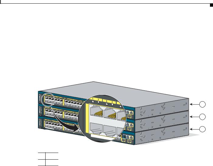
Stack LED
The stack LED shows the sequence of member switches in a stack. Up to four switches can be members of a stack. The first four port LEDs show the switch member number. Figure 1-8 shows the LEDs on the first switch, which is stack member number 1. For example, if you press the Mode button and select Stack, the port LED 1 blinks green. The LEDs for port 2 and 3 are solid green, as these represent the member numbers of other stack members. The other port LEDs are off because there are no more members in the stack.
Figure 1-8 |
Stack LED |
1X
2X
POWER OVER |
23X |
25X |
|
|
|
ETHERNET 740W |
|
1X |
|
|
|
|
|
|
|
24X |
26X |
2960XS Series |
PoE 10G |
|
|
|
|
|
|
|
|
|
2 |
|
24X |
26X |
|
|
|
2960XS Series |
PoE 10G |
|
|
|
|
|
|
|
|
|
2X |
|
|
2 |
|
|
|
|
|
2960XS Series |
|
|
24X |
26X |
|
|
|
PoE 10G |
|
|
|
POWER |
|
|
|
|
|
|
OVER |
ETHERNET |
|
|
|
|
|
|
740W |
|
||
|
|
|
|
|
||
|
|
|
|
|
|
|
|
|
|
|
|
2 |
|
1 |
Stack member 1 |
3 Stack member 3 |
2 |
Stack member 2 |
|
1
2
3
206696
When you select the Stack LED, the respective Stack LEDs are green when the stack ports (on the switch rear panel) are up, and the respective Stack LEDs are amber when the ports are down. SFP+ module port LEDs 1 and 2 on the switch show the status for stack ports 1 and 2, respectively.
If the port LEDs are green on all the switches in the stack, the stack is operating at full bandwidth. If any port LED is not green, the stack is not operating at full bandwidth.
|
|
Catalyst 2960-S Switch Hardware Installation Guide |
|
|
|
|
|
|
|||
|
OL-19732-04 |
|
|
1-15 |
|
|
|
|
|
||
Chapter 1 Product Overview
Front Panel
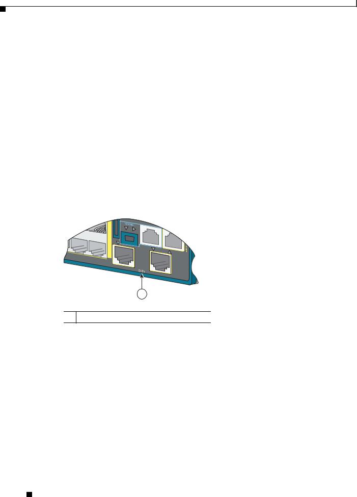
Console LEDs
The console LEDs show which console port is in use.
Figure 1-9 |
Console LEDs |
Catalyst |
|
|
|
|
|
2960-S |
|
|
|
|
Series |
|
|
|
|
PoE+ |
|
|
|
47X |
10G |
|
|
206697 |
|
Catalyst |
|
|
|
|
2960-S |
Series |
PoE+ 10G |
|
|
47X |
|||
|
48X |
|
|
|
|
1 |
|
|
|
|
|
2 |
|
|
48X |
|
|
|
|
1 2
1USB console LED
2RJ-45 console LED
If you connect a cable to a console port, the switch automatically uses that port for console communication. If you connect two console cables, the USB console port has priority.
Table 1-10 lists the console and USB port LED colors and their meanings.
Table 1-10 |
RJ-45 and USB Console LEDs |
||
|
|
|
|
LED |
|
Color |
Description |
|
|
|
|
RJ-45 console port |
Green |
RJ-45 console port is active. |
|
|
|
|
When this LED is on, the USB console port LED is off. |
|
|
|
|
|
|
Off |
The port is not active, and the USB console port is active. |
|
|
|
|
USB console port |
Green |
USB console port is active. |
|
|
|
|
When this LED is on, the RJ-45 console port LED is off. |
|
|
|
|
|
|
Off |
The port is not active, and the RJ-45 console port is active. |
|
|
|
|
Catalyst 2960-S Switch Hardware Installation Guide
1-16 |
OL-19732-04 |
|
|
Chapter 1 Product Overview
Rear Panel
Ethernet Management Port LED
Table 1-11 |
Ethernet Management Port LED |
|
|
Color |
Description |
|
|
Green |
Active link to PC. |
|
|
Off |
Inactive link. |
|
|
Amber |
POST failure. |
|
|
Rear Panel
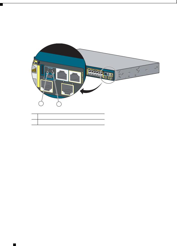
The rear panel of the stacking-capable switches have a FlexStack module slot, a fan exhaust, and an AC power connector. The stacking-capable switch is available with or without an RPS connector. See Figure 1-10 and Figure 1-11.
Figure 1-10 Catalyst 2960-S Switch Rear Panel with Stacking Module Slot and RPS connector
|
|
RATING |
|
|
|
100-240~ |
|
|
|
12-6A, |
50-60Hz |
|
|
|
|
1 |
|
|
|
2 |
|
|
|
|
|
3 |
4 |
|
|
|
|
1 FlexStack module slot and |
3 |
RPS connector |
|
cover |
|
|
|
2 Fan exhaust |
4 |
AC power connector |
|
206698
|
|
Catalyst 2960-S Switch Hardware Installation Guide |
|
|
|
|
|
|
|||
|
OL-19732-04 |
|
|
1-17 |
|
|
|
|
|
||
Chapter 1 Product Overview
Rear Panel
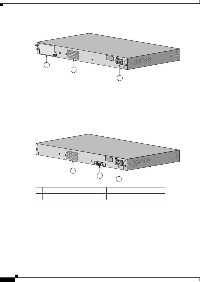
Figure 1-11 Catalyst 2960-S Switch Rear Panel with Stacking Module Slot and without RPS connector
RATING |
|
100-240~ |
|
12-6A, |
50-60Hz |
1
2
3
344241
1 |
FlexStack module slot and cover |
3 |
AC power connector |
|
|
|
|
2 |
Fan exhaust |
|
|
|
|
|
|
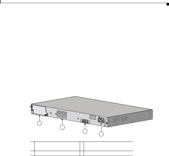
The rear panel of the nonstacking-capable switches have a fan exhaust, and an AC power connector. The nonstacking-capable switch is available with or without an RPS connector. See Figure 1-12 and Figure 1-13.
Figure 1-12 Catalyst 2960-S Switch Rear Panel with an RPS connector
|
|
RATING |
|
|
|
100-240~ |
|
|
|
12-6A, |
50-60Hz |
|
|
|
|
|
|
1 |
|
|
|
2 |
3 |
|
|
|
|
1 |
Fan exhaust |
3 AC power connector |
|
2 |
RPS connector |
|
|
206699
|
Catalyst 2960-S Switch Hardware Installation Guide |
1-18 |
OL-19732-04 |

Chapter 1 Product Overview
Rear Panel
Figure 1-13 Catalyst 2960-S Switch Rear Panel without an RPS connector
RATING |
|
100-240~ |
|
12-6A, |
50-60Hz |
1
2
1 |
Fan exhaust |
2 |
AC power connector |
|
|
|
|
FlexStack Ports
344242
The stacking-capable switch models support stacking with the optional stack kit. It has the FlexStack module (hot-swappable) to insert in the slot in the switch rear panel, and a 0.5-meter FlexStack cable to connect the FlexStack module ports.
For FlexStack module installation, see “Installing the FlexStack Module” section on page 2-7. For stack cabling, see “Connecting the FlexStack Cables” section on page 2-17.
Caution Use only approved cables, and connect only to other Catalyst 2960-S switches. Equipment might be damaged if connected to other nonapproved Cisco cables or equipment.
RPS Connector
Note RPS is not supported on the Catalyst 2960S-F48FPS-L, 2960S-F48LPS-L, 2960S-F24PS-L, 2960S-F48TS-L, 2960S-F24TS-L, 2960S-F48TS-S, and 2960S-F24TS-S switches.
The Cisco RPS 2300 (model PWR-RPS2300) supports the Catalyst 2960-S switch.
Warning Attach only the following Cisco RPS model to the RPS receptacle: RPS2300. Statement 370
Connect the switch and the redundant power system to different AC power sources.
Use this cable for the RPS: CAB-RPS2300-E.
Cisco RPS 2300
The Cisco RPS 2300 is a redundant power system that can support six external network devices and provide power to one or two failed devices at a time. It senses when the internal power supply of a connected device fails and provides power to the failed device, preventing loss of network traffic. For information, see the “Related Publications” section.
|
|
Catalyst 2960-S Switch Hardware Installation Guide |
|
|
|
|
|
|
|||
|
OL-19732-04 |
|
|
1-19 |
|
|
|
|
|
||

Chapter 1 Product Overview
Management Options
The Cisco RPS 2300 has two output levels: –52 V and 12 V with a total maximum output power of 2300 W.
All supported and connected switches can simultaneously communicate with the RPS 2300. You can configure these RPS 2300 features through the switch software:
•Enable RPS active or standby mode for each connected switch
•Configure switch priority for RPS support
•List the connected switches and the power-supply module sizes
•Obtain reports when a switch is powered by the RPS
•Obtain status reports for the RPS power-supply module
•Read and monitor backup, failure, and exception history
AC Power Connector
The switch is powered through the internal power supply. The internal power supply is an autoranging unit that supports input voltages between 100 and 240 VAC. Use the supplied AC power cord to plug it into an AC power outlet.
Management Options
•Cisco Network Assistant
Cisco Network Assistant is a PC-based network management GUI application for LANs of small and medium-sized businesses. You can use the GUI to configure and manage switch clusters or standalone switches. Cisco Network Assistant is available at no cost and can be downloaded from this URL:
http://www.cisco.com/pcgi-bin/tablebuild.pl/NetworkAssistant
For information on starting the Network Assistant application, see the Getting Started with Cisco Network Assistant guide on Cisco.com.
•Device manager
You can use the device manager in the switch memory to manage individual and standalone switches. This web interface provides configuration and monitoring from anywhere in your network. For information, see the switch getting started guide and the device manager online help.
•Cisco IOS CLI
You can configure and monitor the switch and switch cluster members from the CLI. Access the CLI by connecting your management station to the switch console port or by using Telnet from a remote management station. See the switch command reference on Cisco.com for information.
•CiscoWorks application
The CiscoWorks LAN Management Solution (LMS) is a suite of management tools that simplify the configuration, administration, monitoring, and troubleshooting of Cisco networks. See the LMS documentation for information:
http://cisco.com/go/lms
|
Catalyst 2960-S Switch Hardware Installation Guide |
1-20 |
OL-19732-04 |

Chapter 1 Product Overview
Management Options
•CiscoView application
The CiscoView device-management application displays the switch image that you can use to view switch status and performance information and set configuration parameters. The CiscoView application, which you purchase separately, can be a standalone application or part of a Simple Network Management Protocol (SNMP) platform. For information, see the CiscoView documentation at this URL: http://www.cisco.com/en/US/products/sw/cscowork/ps4565/tsd_products_support_series_home.ht ml
•Cisco Configuration Engine
The Cisco Configuration Engine is network management software that automates initial configurations and configuration updates. It generates device-specific configuration changes, sends them to the device, executes the configuration change, and logs the results. For information about Cisco Configuration Engine, see the software configuration guide on Cisco.com.
•SNMP network management
You can manage switches from a Simple Network Management Protocol (SNMP)-compatible management station that is running platforms such as HP OpenView or SunNet Manager. The switch supports a comprehensive set of Management Information Base (MIB) extensions and four Remote Monitoring (RMON) groups. See the switch software configuration guide on Cisco.com and the documentation that came with your SNMP application for information.
•Cisco Security Manager
Cisco Security Manager (Security Manager) manages security policies on Cisco security devices. Security Manager supports integrated provisioning of firewall, IPS, and VPN (site-to-site, remote access, and SSL) services across devices. For information, see the User Guide for Cisco Security Manager 3.2.2.
•Catalyst Smart Operations
The Smart Install feature provides a single point of management (director) in a network. You can use it to provide a zero touch image and configuration upgrade of newly deployed switches and image and configuration downloads for any client switches. For information, see the Cisco Smart Install Configuration Guide on Cisco.com.
Auto Smartports macros dynamically configure ports based on the device type detected on the port. When the switch detects a new device, it applies the appropriate Auto Smartports macro on the port. For information about configuring Auto Smartports, see the switch software configuration guide on Cisco.com.
Network Configurations
See the switch software configuration guide on Cisco.com for network configuration concepts and examples of using the switch to create dedicated network segments and interconnecting the segments through Fast Ethernet and Gigabit Ethernet connections.
|
|
Catalyst 2960-S Switch Hardware Installation Guide |
|
|
|
|
|
|
|||
|
OL-19732-04 |
|
|
1-21 |
|
|
|
|
|
||
Loading...