


 Loading...
Cisco 170 Series Hardware Installation
Guide
For Cisco C170 Email Security Appliance, Cisco M170 Content Security Management Appliance, and Cisco S170 Web Security Appliance
Americas Headquarters
Cisco Systems, Inc. 170 West Tasman Drive
San Jose, CA 95134-1706 USA http://www.cisco.com Tel: 408 526-4000
800 553-NETS (6387) Fax: 408 527-0883
Text Part Number: OL-28365-01
THE SPECIFICATIONS AND INFORMATION REGARDING THE PRODUCTS IN THIS MANUAL ARE SUBJECT TO CHANGE WITHOUT NOTICE. ALL STATEMENTS, INFORMATION, AND RECOMMENDATIONS IN THIS MANUAL ARE BELIEVED TO BE ACCURATE BUT ARE PRESENTED WITHOUT WARRANTY OF ANY KIND, EXPRESS OR IMPLIED. USERS MUST TAKE FULL RESPONSIBILITY FOR THEIR APPLICATION OF ANY PRODUCTS.
THE SOFTWARE LICENSE AND LIMITED WARRANTY FOR THE ACCOMPANYING PRODUCT ARE SET FORTH IN THE INFORMATION PACKET THAT SHIPPED WITH THE PRODUCT AND ARE INCORPORATED HEREIN BY THIS REFERENCE. IF YOU ARE UNABLE TO LOCATE THE SOFTWARE LICENSE OR LIMITED WARRANTY, CONTACT YOUR CISCO REPRESENTATIVE FOR A COPY.
The following information is for FCC compliance of Class A devices: This equipment has been tested and found to comply with the limits for a Class A digital device, pursuant to part 15 of the FCC rules. These limits are designed to provide reasonable protection against harmful interference when the equipment is operated in a commercial environment. This equipment generates, uses, and can radiate radio-frequency energy and, if not installed and used in accordance with the instruction manual, may cause harmful interference to radio communications. Operation of this equipment in a residential area is likely to cause harmful interference, in which case users will be required to correct the interference at their own expense.
The following information is for FCC compliance of Class B devices: This equipment has been tested and found to comply with the limits for a Class B digital device, pursuant to part 15 of the FCC rules. These limits are designed to provide reasonable protection against harmful interference in a residential installation. This equipment generates, uses and can radiate radio frequency energy and, if not installed and used in accordance with the instructions, may cause harmful interference to radio communications.
However, there is no guarantee that interference will not occur in a particular installation. If the equipment causes interference to radio or television reception, which can be determined by turning the equipment off and on, users are encouraged to try to correct the interference by using one or more of the following measures:
•Reorient or relocate the receiving antenna.
•Increase the separation between the equipment and receiver.
•Connect the equipment into an outlet on a circuit different from that to which the receiver is connected.
•Consult the dealer or an experienced radio/TV technician for help.
Modifications to this product not authorized by Cisco could void the FCC approval and negate your authority to operate the product.
The Cisco implementation of TCP header compression is an adaptation of a program developed by the University of California, Berkeley (UCB) as part of UCB’s public domain version of the UNIX operating system. All rights reserved. Copyright © 1981, Regents of the University of California.
NOTWITHSTANDING ANY OTHER WARRANTY HEREIN, ALL DOCUMENT FILES AND SOFTWARE OF THESE SUPPLIERS ARE PROVIDED “AS IS” WITH ALL FAULTS. CISCO AND THE ABOVE-NAMED SUPPLIERS DISCLAIM ALL WARRANTIES, EXPRESSED OR IMPLIED, INCLUDING, WITHOUT LIMITATION, THOSE OF MERCHANTABILITY, FITNESS FOR A PARTICULAR PURPOSE AND NONINFRINGEMENT OR ARISING FROM A COURSE OF DEALING, USAGE, OR TRADE PRACTICE.
IN NO EVENT SHALL CISCO OR ITS SUPPLIERS BE LIABLE FOR ANY INDIRECT, SPECIAL, CONSEQUENTIAL, OR INCIDENTAL DAMAGES, INCLUDING, WITHOUT LIMITATION, LOST PROFITS OR LOSS OR DAMAGE TO DATA ARISING OUT OF THE USE OR INABILITY TO USE THIS MANUAL, EVEN IF CISCO OR ITS SUPPLIERS HAVE BEEN ADVISED OF THE POSSIBILITY OF SUCH DAMAGES.
Cisco and the Cisco logo are trademarks or registered trademarks of Cisco and/or its affiliates in the U.S. and other countries. To view a list of Cisco trademarks, go to this URL: www.cisco.com/go/trademarks. Third-party trademarks mentioned are the property of their respective owners. The use of the word partner does not imply a partnership relationship between Cisco and any other company. (1110R)
Any Internet Protocol (IP) addresses and phone numbers used in this document are not intended to be actual addresses and phone numbers. Any examples, command display output, network topology diagrams, and other figures included in the document are shown for illustrative purposes only. Any use of actual IP addresses or phone numbers in illustrative content is unintentional and coincidental.
Cisco 170 Series Hardware Installation Guide
© 2012 Cisco Systems, Inc. All rights reserved.

|
|
|
|
|
|
|
|
|
C O N T E N T S |
||||
|
|
|
Preface vii |
|
|
|
|
|
|
|
|
|
|
|
|
|
Contents |
vii |
|
|
|
|
|
|
|
|
|
|
|
|
Document Objectives |
vii |
|
|
|
|
|
|
|
|
|
|
|
|
Audience |
vii |
|
|
|
|
|
|
|
|
|
|
|
|
Document Organization |
viii |
|
|
|
|
|
|
|
||
|
|
|
Document Conventions |
viii |
|
|
|
|
|
|
|
||
|
|
|
Installation Warnings |
ix |
|
|
|
|
|
|
|
|
|
|
|
|
Where to Find Safety and Warning Information |
xiii |
|
|
|
|
|||||
|
|
|
Related Documentation |
xiii |
|
|
|
|
|
|
|
||
|
|
|
Obtaining Documentation and Submitting a Service Request |
xiii |
|||||||||
|
|
Cisco 170 Series Appliance |
|
|
|
|
|
|
|
|
|||
C H A P T E R |
1 |
1-1 |
|
|
|
|
|
|
|
||||
|
|
|
Cisco 170 Series Overview |
1-1 |
|
|
|
|
|
|
|
||
|
|
|
Cisco C170 Email Security Appliance |
1-2 |
|
|
|
|
|
||||
|
|
|
Cisco M170 Content Security Management Appliance |
1-2 |
|
|
|
||||||
|
|
|
Cisco S170 Web Security Appliance |
1-2 |
|
|
|
|
|
||||
|
|
|
Cisco 170 Series Appliance Panels |
1-3 |
|
|
|
|
|
|
|||
|
|
|
Front Panel LEDs |
1-3 |
|
|
|
|
|
|
|
|
|
|
|
|
Rear Panel LEDs |
1-5 |
|
|
|
|
|
|
|
|
|
|
|
|
Rear Panel Ports |
1-6 |
|
|
|
|
|
|
|
|
|
|
|
|
Alarm LED |
1-8 |
|
|
|
|
|
|
|
|
|
|
|
|
Management Interface |
1-8 |
|
|
|
|
|
|
|
||
|
|
|
Hard Disk Drives 1-8 |
|
|
|
|
|
|
|
|
|
|
|
|
|
Hardware and Technical Specifications |
1-9 |
|
|
|
|
|
||||
|
|
Preparing for Installation |
|
|
|
|
|
|
|
|
|||
C H A P T E R |
2 |
2-1 |
|
|
|
|
|
|
|
||||
|
|
|
Installation Overview |
2-1 |
|
|
|
|
|
|
|
|
|
|
|
|
Safety Recommendations |
2-2 |
|
|
|
|
|
|
|
||
|
|
|
Maintaining Safety with Electricity |
2-2 |
|
|
|
|
|
||||
|
|
|
Preventing Electrostatic Discharge Damage |
2-3 |
|
|
|
|
|||||
|
|
|
Working in an ESD Environment |
2-3 |
|
|
|
|
|
||||
|
|
|
General Site Requirements |
2-4 |
|
|
|
|
|
|
|
||
|
|
|
Site Environment |
2-4 |
|
|
|
|
|
|
|
|
|
|
|
|
|
|
|
|
|
|
Cisco 170 Series Hardware Installation Guide |
|
|
|
|
|
|
|
|
|
|
|
|
|
|
||||
|
|
|
|
|
|
|
|
|
|
|
|
|
|
|
OL-28365-01 |
|
|
|
|
|
|
|
|
|
iii |
|
|
|
|
|
|
|
|
|
|
|
|
|
|||

Contents
Preventive Site Configuration |
2-4 |
Power Supply Considerations |
2-5 |
Configuring Equipment Racks |
2-7 |
C H A P T E R 3 |
Installing and Connecting the Cisco 170 Series Appliance |
3--1 |
||
|
Installing the Cisco 170 Series Appliance with Slide Rails |
3--1 |
||
|
Verifying the Box Contents |
3--1 |
|
|
|
Disassembling the Slide Rail |
3-0 |
|
|
|
Attaching Inner Rails to the Appliance 3-1 |
|
||
|
Verifying the Rack Type |
3-2 |
|
|
|
Securing Round Hole Racks |
3-3 |
|
|
|
Securing Threaded Hole Racks 3-3 |
|
||
|
Attaching the Outer Slide Rail to Round and Square Hole Racks 3-4 |
|||
|
Attaching the Outer Slide Rail to Threaded Hole Racks |
3-5 |
||
|
Installing the Appliance |
3-6 |
|
|
|
Securing the Appliance |
3-7 |
|
|
|
Rack Mounting the Cisco 170 Series Appliance |
3-8 |
|
|
Guidelines and Recommendations |
3-8 |
|
|
Rack Mounting the Cisco C170, Cisco M170, or Cisco S170 Appliances 3-8 |
||
|
Connecting the Interface Cables and Verifying Connectivity 3-10 |
||
|
Maintaining the Cisco 170 Series Appliance |
|
|
C H A P T E R 4 |
4-1 |
||
|
Fixed AC Power Supply 4-1 |
|
|
|
Removing and Installing Hard Disk Drives |
4-1 |
|
|
Maintenance Scenarios 4-2 |
|
|
|
Replacing the Hard Disk Drives 4-2 |
|
|
|
Contacting Service and Support |
4-3 |
|
Identifying Cable Pinouts A-1 |
|
A P P E N D I X A |
|
|
|
10/100/1000BaseT Connectors |
A-1 |
|
Console Port (RJ-45) A-2 |
|
|
RJ-45 to DB-9 A-3 |
|
Cisco 170 Series Hardware Installation Guide
|
iv |
OL-28365-01 |
|
|
|

Preface
Contents
This preface includes the following sections:
•Document Objectives, page vii
•Audience, page vii
•Document Organization, page viii
•Document Conventions, page viii
•Installation Warnings, page ix
•Where to Find Safety and Warning Information, page xiii
•Related Documentation, page xiii
•Obtaining Documentation and Submitting a Service Request, page xiii
Document Objectives
This guide describes how to install and maintain the Cisco 170 series appliance. The information in this guide applies to the following Cisco 170 series (Cisco 170 series) appliance models:
•Cisco C170 Email Security Appliance (Cisco C170)
•Cisco M170 Content Security Management Appliance (Cisco M170)
•Cisco S170 Web Security Appliance (Cisco S170)
References to “Cisco 170 series” and “appliance” applies to the listed models, unless specifically noted otherwise.
Audience
This guide is for experienced network security administrators who install, configure, and maintain Cisco content security appliances in their networks.
Cisco 170 Series Hardware Installation Guide
|
OL-28365-01 |
vii |
|

Document Organization
This guide includes the following sections:
Section |
Title |
Description |
|
|
|
1 |
“Cisco 170 Series Appliance” |
Describes the Cisco 170 series appliance and its |
|
|
specifications. |
|
|
|
2 |
“Preparing for Installation” |
Describes steps to follow before installing the |
|
|
Cisco 170 series appliance. |
|
|
|
3 |
“Installing and Connecting the Cisco |
Describes how to install the Cisco 170 series |
|
170 Series Appliance” |
appliance in a rack and provides information |
|
|
about how to connect interface cables. |
|
|
|
4 |
“Maintaining the Cisco 170 Series |
Describes the power supply provided with the |
|
Appliance” |
Cisco 170 series appliance and how to remove and |
|
|
replace hard disk drives (HDDs). |
|
|
|
A |
“Identifying Cable Pinouts” |
Describes the cable pinouts. |
|
|
|
Document Conventions
Command descriptions use these conventions:
•Braces ({ }) indicate a required choice.
•Square brackets ([ ]) indicate optional elements.
•Vertical bars (|) separate alternative, mutually exclusive elements.
•Boldface indicates commands and keywords that are entered literally as shown.
•Italics indicate arguments for which you supply values.
Examples use these conventions:
•Examples depict screen displays and the command line in screen font.
•Information you need to enter in examples is shown in boldface screen font.
•Variables for which you must supply a value are shown in italic screen font. Graphical user interface examples uses these conventions:
•Boldface indicates buttons and menu items.
•Selecting a menu item (or pane) is indicated by the following convention: Choose Start > Settings > Control Panel.
Note Means reader take note. Notes contain helpful suggestions or references to material not covered in the manual.
Cisco 170 Series Hardware Installation Guide
|
viii |
OL-28365-01 |
|
|
|

Installation Warnings
Before installing the appliance, be sure to read the Safety and Compliance Guide for the Cisco Content Security Appliances document at: http://www.cisco.com/en/US/docs/security/esa/hw/SafetyAndComplianceGuide.pdf. This document contains important safety information. This section includes the following warnings:
•Power Supply Disconnection Warning, page ix
•Jewelry Removal Warning, page ix
•Wrist Strap Warning, page x
•Work During Lightning Activity Warning, page x
•Work During Lightning Activity Warning, page x
•Installation Instructions Warning, page x
•Chassis Warning for Rack-Mounting and Servicing, page x
•SELV Circuit Warning, page x
•Ground Conductor Warning, page x
•Blank Faceplates and Cover Panels Warning, page xi
•Product Disposal Warning, page xi
•Short-Circuit Protection Warning, page xi
•Compliance with Local and National Electrical Codes Warning, page xi
•TN Power Warning, page xi
•TN Power Warning, page xi
•TN Power Warning, page xi
•Multiple Power Cord, page xi
•Multiple Power Cord, page xi
•Circuit Breaker (15A) Warning, page xi
•Grounded Equipment Warning, page xii
•Safety Cover Requirement, page xii
•Faceplates and Cover Panel Requirement, page xii
Power Supply Disconnection Warning
Warning Before working on a chassis or working near power supplies, unplug the power cord on AC units.
Statement 12
Jewelry Removal Warning
Warning Before working on equipment that is connected to power lines, remove jewelry (including rings, necklaces, and watches). Metal objects will heat up when connected to power and ground and can cause serious burns or weld the metal object to the terminals. Statement 43
Cisco 170 Series Hardware Installation Guide
|
OL-28365-01 |
ix |
|
Wrist Strap Warning
Warning During this procedure, wear grounding wrist straps to avoid ESD damage to the card. Do not directly touch the backplane with your hand or any metal tool, or you could shock yourself. Statement 94
Work During Lightning Activity Warning
Warning Do not work on the system or connect or disconnect cables during periods of lightning activity.
Statement 1001
Installation Instructions Warning
Warning Read the installation instructions before connecting the system to the power source. Statement 1004
Chassis Warning for Rack-Mounting and Servicing
Warning To prevent bodily injury when mounting or servicing this unit in a rack, you must take special precautions to ensure that the system remains stable. The following guidelines are provided to ensure your safety: This unit should be mounted at the bottom of the rack if it is the only unit in the rack.When mounting this unit in a partially filled rack, load the rack from the bottom to the top with the heaviest component at the bottom of the rack.If the rack is provided with stabilizing devices, install the stabilizers before mounting or servicing the unit in the rack. Statement 1006
SELV Circuit Warning
Warning To avoid electric shock, do not connect safety extra-low voltage (SELV) circuits to telephone-network voltage (TNV) circuits. LAN ports contain SELV circuits, and WAN ports contain TNV circuits. Some LAN and WAN ports both use RJ-45 connectors. Use caution when connecting cables. Statement 1021
Ground Conductor Warning
Warning This equipment must be grounded. Never defeat the ground conductor or operate the equipment in the absence of a suitably installed ground conductor. Contact the appropriate electrical inspection authority or an electrician if you are uncertain that suitable grounding is available. Statement 1024
Cisco 170 Series Hardware Installation Guide
|
x |
OL-28365-01 |
|
|
|
Blank Faceplates and Cover Panels Warning
Warning Blank faceplates and cover panels serve three important functions: they prevent exposure to hazardous voltages and currents inside the chassis; they contain electromagnetic interference (EMI) that might disrupt other equipment; and they direct the flow of cooling air through the chassis. Do not operate the system unless all cards, faceplates, front covers, and rear covers are in place. Statement 1029
Product Disposal Warning
Warning Ultimate disposal of this product should be handled according to all national laws and regulations.
Statement 1040
Short-Circuit Protection Warning
Warning This product requires short-circuit (overcurrent) protection, to be provided as part of the building installation. Install only in accordance with national and local wiring regulations. Statement 1045
Compliance with Local and National Electrical Codes Warning
Warning Installation of the equipment must comply with local and national electrical codes. Statement 1074
TN Power Warning
Warning The device is designed to work with TN power systems. Statement 19
Multiple Power Cord
Warning This unit has more than one power cord. To reduce the risk of electric shock when servicing a unit, disconnect the power cord of the power strip that the unit is plugged into. Statement 137
Circuit Breaker (15A) Warning
Warning This product relies on the building’s installation for short-circuit (overcurrent) protection. Ensure that a fuse or circuit breaker no larger than 120 VAC, 15A U.S. (240 VAC, 10A international) is used on the phase conductors (all current-carrying conductors). Statement 13
Cisco 170 Series Hardware Installation Guide
|
OL-28365-01 |
xi |
|
Grounded Equipment Warning
Warning This equipment is intended to be grounded. Ensure that the host is connected to earth ground during normal use. Statement 39
Safety Cover Requirement
Warning The safety cover is an integral part of the product. Do not operate the unit without the safety cover installed. Operating the unit without the cover in place will invalidate the safety approvals and pose a risk of fire and electrical hazards. Statement 117
Faceplates and Cover Panel Requirement
Warning Blank faceplates and cover panels serve three important functions: they prevent exposure to hazardous voltages and currents inside the chassis; they contain electromagnetic interference (EMI) that might disrupt other equipment; and they direct the flow of cooling air through the chassis. Do not operate the system unless all cards, faceplates, front covers, and rear covers are in place. Statement 142
Cisco 170 Series Hardware Installation Guide
|
xii |
OL-28365-01 |
|
|
|
Where to Find Safety and Warning Information
For safety and warning information, see the Safety and Compliance Guide for the Cisco Content Security Appliances document at the following URL:
http://www.cisco.com/en/US/docs/security/esa/hw/SafetyAndComplianceGuide.pdf
This document describes the international agency compliance and safety information for the Cisco 170 series. It also includes translations of the safety warnings used in this guide.
Related Documentation
For additional documentation on the Cisco 170 series appliances, see the following:
•Cisco C170 Email Security Appliance: http://www.cisco.com/en/US/products/ps10154/tsd_products_support_series_home.html
•Cisco M170 Content Security Management Appliance: http://www.cisco.com/en/US/partner/products/ps10155/tsd_products_support_series_home.html
•Cisco S170 Web Security Appliance: http://www.cisco.com/en/US/partner/products/ps10164/tsd_products_support_series_home.html
Obtaining Documentation and Submitting a Service Request
For information on obtaining documentation, submitting a service request, and gathering additional information, see the monthly What’s New in Cisco Product Documentation, which also lists all new and revised Cisco technical documentation, at:
http://www.cisco.com/en/US/docs/general/whatsnew/whatsnew.html
Subscribe to the What’s New in Cisco Product Documentation as an RSS feed and set content to be delivered directly to your desktop using a reader application. The RSS feeds are a free service. Cisco currently supports RSS Version 2.0.
Cisco 170 Series Hardware Installation Guide
|
OL-28365-01 |
xiii |
|

Cisco 170 Series Hardware Installation Guide
|
xiv |
OL-28365-01 |
|
|
|
C H A P T E R 1
Cisco 170 Series Appliance
We recommend that you read the entire guide before beginning any of the procedures contained herein.
Warning Only trained and qualified personnel should install, replace, or service this equipment. Statement 49
Caution Read the safety warnings in the Safety and Compliance Guide for the Cisco Content Security Appliances and follow proper safety procedures when performing any tasks in this document. See: http://www.cisco.com/en/US/docs/security/esa/hw/SafetyAndComplianceGuide.pdf.
This chapter describes the Cisco 170 series appliance, including the front and rear panels, LEDs, rear panel ports, and the hardware and technical specifications of the product.
This chapter includes the following sections:
•Cisco 170 Series Overview, page 1-1
•Cisco 170 Series Appliance Panels, page 1-3
•Alarm LED, page 1-8
•Management Interface, page 1-8
•Hard Disk Drives, page 1-8
•Hardware and Technical Specifications, page 1-9
Cisco 170 Series Overview
The Cisco 170 series is a family of next-generation content security appliances capable of providing the following features and functionality for small businesses, branch offices, and organizations:
•Simplified and automated email security
•Web traffic and application visibility and control
•Flexible, comprehensive security control and management
Cisco 170 Series Hardware Installation Guide
|
OL-28365-01 |
1-1 |
|
|
|
Chapter
Cisco C170 Email Security Appliance
Cisco C170 Email Security Appliance (Cisco C170) automatically stops spam, viruses, and other anomalies. It prevents and responds to multilevel threats and includes capabilities such as: spam and virus defense, policy enforcement, email authentication, and centralized and built-in GUI management tools. For information on Cisco C170, see: http://www.cisco.com/en/US/products/ps10154/tsd_products_support_series_home.html
Figure 1-1 shows the Cisco C170 front panel view.
Figure 1-1 Cisco C170 Email Security Appliance
Cisco M170 Content Security Management Appliance
Cisco M170 Content Security Management Appliance (Cisco M170) is a central platform for managing all policy, integrated reporting on traffic data, and email auditing information for the Cisco 170 series appliances. For information on Cisco M170, see: http://www.cisco.com/en/US/partner/products/ps10155/tsd_products_support_series_home.html
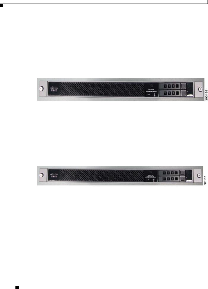
Figure 1-2 shows the Cisco M170 front panel view.
Figure 1-2 Cisco M170 Content Security Management Appliance
Cisco S170 Web Security Appliance
Cisco S170 Web Security Appliance (Cisco S170) is a secure web gateway that combines advanced malware protection, application visibility and control (AVC), acceptable use policy controls, insightful reporting, and secure mobility on a single platform. It is a single platform for administrators to set security policy, control applications at a granular level, and get visibility into web traffic trends at organizations and for remote and mobile users. For information on Cisco S170, see: http://www.cisco.com/en/US/partner/products/ps10164/tsd_products_support_series_home.html
Cisco 170 Series Hardware Installation Guide
1-2 |
OL-28365-01 |
|
|

Chapter
Figure 1-3 shows the Cisco S170 front panel view.
Figure 1-3 Cisco S170 Web Security Appliance
Cisco 170 Series Appliance Panels
This section describes the front and rear Cisco 170 series appliance panels. It includes the following topics:
•Front Panel LEDs, page 1-3
•Rear Panel LEDs, page 1-5
•Rear Panel Ports, page 1-6
Front Panel LEDs
This section describes the front panel LEDs for the Cisco 170 series appliance.
Figure 4 shows the front panel LEDs that are available for the Cisco C170, Cisco M170 and Cisco S170 models (graphic shows the Cisco S170 bezel).
Figure 4 |
Front Panel LEDs for Cisco C170, Cisco M170 and Cisco S170 |
1
Cisco S170 |
|
Web Security Appliance |
|
! |
1 |
|
2 |
2 |
3 |
|
4 |
|
|
1 |
Cisco S170 |
|
|
Web Security Appliance |
|
|
! |
1 |
0 |
|
||
|
2 |
|
303134
Cisco 170 Series Hardware Installation Guide
|
OL-28365-01 |
1-3 |
|
|
|

Chapter
|
|
|
|
|
|
|
|
|
|
|
|
|
LED |
Description |
|
|
|
|
|
1 |
Power button |
A hard switch that turns the system on and off. Once depressed, the |
||
|
|
|
|
button stays in the “on” position: |
|
|
|
|
• On—The power symbol on the button illuminates. |
|
|
|
|
• Off—The power symbol on the button is dark. |
|
|
|
|
|
2 |
Alarm |
Indicates system operating status: |
||
|
|
|
|
• Off—Normal operating system function. |
|
|
|
|
• Solid amber—Critical Alarm indicating one or more of the |
|
|
|
|
following: |
|
|
|
|
– A major failure of a hardware or software component. |
|
|
|
|
– An over-temperature condition. |
|
|
|
|
– The power voltage is outside of the tolerance range. |
|
|
|
|
See the “Alarm LED” section on page 1-8. |
|
|
|
|
|
3 |
HD1 |
Indicates Hard Disk Drive 1 status: |
||
|
|
|
|
• Flashing green—Proportioned to read/write activity. |
|
|
|
|
• Solid amber—Hard disk drive failure. |
|
|
|
|
• Flashing amber—Hard disk drive being rebuilt. |
|
|
|
|
• Off—No hard disk drive present. |
|
|
|
|
|
4 |
HD0 |
Indicates Hard Disk Drive 0 status: |
||
|
|
|
|
• Flashing green—Proportioned to read/write activity. |
|
|
|
|
• Solid amber—Hard disk drive failure. |
|
|
|
|
• Flashing amber—Hard disk drive being rebuilt. |
|
|
|
|
• Off—No hard disk drive present. |
|
|
|
|
|
Cisco 170 Series Hardware Installation Guide
1-4 |
OL-28365-01 |
|
|
Loading...